1
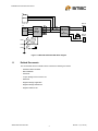
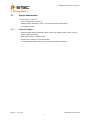
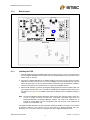
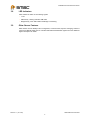
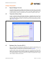
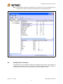
EVB-EMC1043/1053/1063 User Manual
The information contained herein is proprietary to SMSC, and shall be used solely in accordance with the agreement pursuant to which it is provided. Although the information is believed to be accurate, no responsibility is assumed for inaccuracies. SMSC reserves the right to make changes to this document and to specifications and product descriptions at any
time without notice. Neither the provision of this information nor the sale of the described semiconductor devices conveys
any licenses under any patent rights or other intellectual property rights of SMSC or others unless specifically specified
otherwise. The product may contain design defects or errors known as anomalies, including but not necessarily limited to
any which may be identified in this document, which may cause the product to deviate from published specifications.
SMSC products are not designed, intended, authorized or warranted for use in any life support or other application where
product failure could cause or contribute to personal injury or severe property damage. Any and all such uses without prior
written approval of an officer of SMSC will be fully at the risk of the customer. SMSC is a registered trademark of Standard
Microsystems Corporation (“SMSC”).
SMSC DISCLAIMS AND EXCLUDES ANY AND ALL WARRANTIES, INCLUDING WITHOUT LIMITATION ANY AND ALL
IMPLIED WARRANTIES OF MERCHANTABILITY, FITNESS FOR A PARTICULAR PURPOSE, TITLE, AND AGAINST
INFRINGEMENT AND THE LIKE, AND ANY AND ALL WARRANTIES ARISING FROM ANY COURSE OF DEALING OR
USAGE OF TRADE. IN NO EVENT SHALL SMSC BE LIABLE FOR ANY DIRECT, INCIDENTAL, INDIRECT, SPECIAL,
PUNITIVE, OR CONSEQUENTIAL DAMAGES; OR FOR LOST DATA, PROFITS, SAVINGS OR REVENUES OF ANY
KIND; REGARDLESS OF THE FORM OF ACTION, WHETHER BASED ON CONTRACT; TORT; NEGLIGENCE OF
SMSC OR OTHERS; STRICT LIABILITY; BREACH OF WARRANTY; OR OTHERWISE; WHETHER OR NOT ANY REMEDY OF BUYER IS HELD TO HAVE FAILED OF ITS ESSENTIAL PURPOSE, AND WHETHER OR NOT SMSC HAS
BEEN ADVISED OF THE POSSIBILITY OF SUCH DAMAGES.
SMSC EMC1043/1053/1063
1
Revision 1.1 (12-14-06)
EVB-EMC1043/1053/1063 User Manual
1 Overview
The EMC1043/1053/1063 are SMBus temperature sensing ICs with 1 internal and 2 external sensors
in an 8 pin MSOP package. These 3 ICs are targeted at different applications as described in Table 1.1.
Table 1.1 Application Info for Support Temperature Sensors
Temp Sensor
Target Application
EMC1043
Designed for CPUs and GPUs which use a substrate PNP transistor for temperature sensing.
65 and 90nm process geometries are supported. The EMC1043’s default configuration enables
Beta Compensation and Resistance Error Correction (R.E.C.) on both external diodes. The
EMC1043-5 version defaults to Beta Compensation disabled. on external diode 2.
EMC1053
The same as EMC1043 except that Beta Compensation is disabled on both diode channels by
default. R.E.C. is enabled on both channels at power-up.
EMC1063
An ideal solution for AMD CPU thermal diodes, the EMC1063 may also be used with 2N3904
diode-connected transistors. The EMC1063 does not have Beta Compensation or REC features
on external diode channel 1. REC is optional for external diode 2.
This evaluation board (EVB) has 2N3904 diode-connected transistors installed on the PCB for external
diodes 1 and 2. The Beta Compensation function is designed for CPU substrate diodes and is not
compatible with diode-connected transistors such as the 2N3904. For this reason, the EMC1043
default settings are over-ridden by the Register Manager’s initialization code so that Beta
Compensation is disabled.
If your evaluation process requires connecting the EVB to the thermal diodes on Intel or AMD CPUs,
you can modify the PCB by removing the 2N3904s and installing the headers (P2 and P3) for
connection to external diodes over cables. Alternately, you can order the EVB-EMC1043C/1063C,
which is configured with headers for CPU connection. Refer to the schematic, SCH-7040_B0.pdf for
details on EVB circuit options.
Resistance Error Correction can eliminate the affect of series resistance to provide a more accurate
temperature reading. Ideality Factor Configuration is available to accomodate remote diodes with a
wide range of ideality factors. This is especially important for microprocessors, FPGAs, and graphics
chips.
The EVB-EMC1043, EVB-EMC1053 and EVB-EMC1063 are USB-based platforms for evaluating the
EMC1043/1053/1063 ICs. A block diagram of the EVB is shown in Figure 1.1 below.
Revision 1.1 (12-14-06)
SMSC EMC1043/1053/1063
2
EVB-EMC1043/1053/1063 User Manual
P1
SMBus
Remote
Diode1
JP4
P6
DP1
Vdd
USB
Mini-B
LED7
LED6
SCL
USBSMBus
Bridge
SDA
EMC1043
EMC1053
or
EMC1063
Q2
DN1
DP2
JP1
DN2
100ohm
USB
Activity
Remote
Diode2
Q3
Bridge
Activity
Vdd
LED8
Figure 1.1 EMC1043/1053/1063 EVB Block Diagram
1.1
Related Documents
The CD included with the evaluation board contains the following documents:
n
Evaluation Board Checklist
n
Bill Of Materials
n
Schematic
n
Jumper Settings and Connector List
n
Datasheet
n
Register Manager Application
n
Register Manager Readme.txt
n
Register Definition File
SMSC EMC1043/1053/1063
Revision 1.1 (12-14-06)
3
EVB-EMC1043/1053/1063 User Manual
2 Getting Started
2.1
System Requirements
To use the EVB you will need:
2.1.1
n
A PC running Windows 2000 or XP
n
Display resolution 800x600 (or larger to view several windows simultaneously)
n
An available USB port
Feature Summary
n
Windows Register Manager application allows viewing and changing register values as well as
graphing temperature history
n
USB communication to evaluation board
n
Resistive Error Correction can be demonstrated
n
An external SMBus master may also be used (circuit modifications required)
Revision 1.1 (12-14-06)
SMSC EMC1043/1053/1063
4
EVB-EMC1043/1053/1063 User Manual
2.1.2
Board Layout
JP4 (not on
silkscreen)
EMC
1043
EMC1043
Bottom Side
Figure 2.1 EMC1043/1053/1063 Board Outline and Silkscreen
2.1.3
Installing the EVB
1. Install the Register Manager (RegMan) application and device driver on a PC by running Setup.exe
from the RegMan distribution CD. A revision history and install/uninstall notes may be found in the
readme.txt file on the disk.
2. Connect the supplied USB cable to an available USB port on the PC. Plug the “mini-B” end of the
USB cable into EVB connector P6. The +3.3V and Bridge ACT LEDs should illuminate. After the
EVB is connected to the PC the “Find New Hardware” wizard will pop up for USB driver installation.
Follow the instructions in the readme.txt file to complete the installation process.
3. Start the EVB Software by selecting the Register Manager application from the SMSC folder from
the Programs Windows Start menu. The EVB will initialize and the Register Manager Help screen
will appear as in Figure 2.2. The USBAct LED should be blinking when the Register Manager is
running.
Note: The Windows Register Manager application allows viewing and changing register values for a
variety of EVBs including the EMC1 001, EMC1002, EMC1023, EMC1033 and
EMC1043/1053/1063. The Register Manager software only needs to be installed once to
support all of these EVBs. The list of supported EVBs may be found in the readme.txt file
included on the distribution CD.
The EMC1043/1053/1063 power up with temperature monitoring disabled. The monitor can be started
by selecting “Started” in the combo box on the upper-left of the Register Manager menu bar.
Alternately, you can start the monitor by clearing bit 6 in the Configuration Register, 0x09.
SMSC EMC1043/1053/1063
Revision 1.1 (12-14-06)
5
EVB-EMC1043/1053/1063 User Manual
..
Figure 2.2 Register Manager Help Screen
Revision 1.1 (12-14-06)
SMSC EMC1043/1053/1063
6
EVB-EMC1043/1053/1063 User Manual
3 Circuit Description
3.1
Introduction
The EMC1043/1053/1063 EVB provides the means to demonstrate EMC1043/1053/1063 features and
to view and modify registers. LED Indicators and test points are included to show status information.
3.2
EMC1043/1053/1063
The EMC1043/1053/1063 is a family of SMBus temperature sensors with 1 internal and 2 external
sensors in an 8 pin MSOP package. Communications with the EMC1043/1053/1063 sensors is via the
SMBus.
3.3
USB to SMBus Bridge
The USB to SMBus bridge is based on an 8051 microcontroller with integrated USB and SMBus
interfaces as well as internal flash and RAM. During EVB manufacture, firmware is loaded into the
bridge that provides the interface between the SMBus and the USB driver. Power is sourced to the
MCU from the USB interface.
3.4
Remote Diode with Resistance Error Correction (R.E.C.)
Two diode-connected 2N3904 transistors are mounted on the EVB, labeled Remote1 and Remote2.
The Remote2 diode DP signal path has a series resistor to demonstrate the EMC1043/1053/1063’s
R.E.C. feature. The resistor may be effectively removed from the circuit by installing a jumper on JP1.
See the Jumper Settings and Connection List for details on jumper settings.
3.5
Power Source
This demo board derives +5V power from the USB port. The bridge microcontroller has an internal
voltage regulator that supplies +3.3V to the EMC1043/1053/1063 and other EVB circuits.
3.6
Direct SMBus Connect Option
It is also possible to connect an external SMBus master to the EMC1043/1053/1063 EVB. A few
modifications to the circuit are required:
3.7
n
Cut 3 traces connecting JP4 pins 3-4, 5-6 and 7-8 on the bottom side of the PCB. This will
disconnect the USB bridge from the SMBus. The pullup resistors for the SMBus SDA, and SCL
signals are also disconnected so external pullups will need to be supplied by the SMBus Master.
n
Install P1 or JP4 to provide an SMBus connector. See the Jumper Settings and Connection List
for details.
n
Optionally remove zero ohm resistor R31. When removed, the USB to SMBus bridge will not supply
+3.3V to the circuitry so power will need to be provided from an external source. If R31 is left
installed, power will be supplied from the USB connector when connected to a computer or USB
hub.
Test Points
Test points are provided for:
n
Ground
n
+3.3V power
n
+5V_USB power
SMSC EMC1043/1053/1063
Revision 1.1 (12-14-06)
7
EVB-EMC1043/1053/1063 User Manual
3.8
LED Indicators
LEDs indicate the status of the following signals:
3.9
n
+3.3V
n
USB Activity - blinking indicates USB traffic
n
Bridge Activity, when ON indicates the Bridge is functioning
Other Sensor Features
Other features such as Ideality Factor Configuration, Conversion Rate, Dynamic Averaging, Hottest of
2 Zones and Standby Mode can be controlled with EMC1043/1053/1063 registers. See the datasheet
register description for details.
Revision 1.1 (12-14-06)
SMSC EMC1043/1053/1063
8
EVB-EMC1043/1053/1063 User Manual
4 Demo Description
4.1
Register Manager Overview
The Register Manager application (RegMan) initially displays the main Help screen, where detailed
description of the application’s features may be found. The Help screens can be displayed at any time
by selecting Help from the menubar or pressing the ? button on the toolbar. RegMan enables the user
to display temperature readings, set temperature limits and read/write configuration register values.
4.2
Temperature History Graph
To open a Temperature History Graph window, select Plot -> Temperature History Plot from the
menubar. The history plot continuously updates the temperature reported by the temp sensor. There
are several display options, including which temperatures to display (internal, external, external2),
whether limits should be displayed, and if so, for which temp sensor. See a typical Temperature History
Graph in Figure 4.1 below:
Figure 4.1 EMC1043 Temperature History Graph
..
4.3
Resistance Error Correction (R.E.C.)
R.E.C. is normally enabled in EMC1043 and EMC1053 and is optionial for external diode 2 on th
EMC1063. This feature may be disabled for demonstration purposes by writing a “0” to bit 0 of
Configuration Register 2 at address 0x04. This operation is illustrated in Figure 4.2.
To show the R.E.C. feature, remove the jumper on JP1 pins 1-2. This will insert a 100 ohm series
resistor into the circuit and cause a temperature reading error of approximately 60oC. Replace the
jumper and the temperature will return to its correct reading. Now enable R.E.C. by writing a “1” to bit
0 of Configuration Register 2 at address 0x04. With R.E.C. enabled, the temperature will not change
when the jumper is removed and re-inserted.
SMSC EMC1043/1053/1063
Revision 1.1 (12-14-06)
9
EVB-EMC1043/1053/1063 User Manual
Note: The temperature reported by the EMC1043 may increase by 2-3oC when disabled due to the
production trim method. The EMC1053 and EMC1063 do not exhibit this behavior.
Figure 4.2 Configuration Register Write to Disable R.E.C.
4.4
Ideality Factor Correction
The Ideality Factor can be adjusted in Ideality Factor Registers 0x27 and 0x28. These registers will
normally hold the default value which is correct for the diodes installed on the EVB. Increasing or
decreasing the value will cause a corresponding change in the temperature reading.
Revision 1.1 (12-14-06)
SMSC EMC1043/1053/1063
10