1
LABORATORY GRADE
REMOTE PROGRAMMING
SWITCHING MODE DC regulated
Power Supplies
SDP Series
SDP – 2210 / 2405 / 2603
User Manual
7673-2405-0005
Rev.8 10/2004
Table of Contents
1. Important Safety Instructions and Precautions For Use...................................................1
2. Technical Specifications of SDP Series Power Supply.......................................................3
3. Introduction...........................................................................................................................4
4. Control and Indicators.........................................................................................................5
5. General Operation Principle...............................................................................................6
5.1 Quick Reference of Keypad Functions........................................................................6
5.2 Quick Reference of The Timed and Preset Program...................................................7
6. Operating Instructions..........................................................................................................8
6.1 Setting of Operating Mode
6.1.1. Enable/Disable Output.............................................................................9
6.1.2. Lock / Unlock theKeypad and Jog Dial...................................................9
6.1.3. PC Interface RS-232//RS-485 Selection..................................................9
6.1.4. Upper Voltage Limit Setting...................................................................10
6.1.5. Output Enable/Disable at Power Up.......................................................10
6.2Basic Operation
6.2.1.Setting of Voltage and Current by Jog Dial and UP & DN Key .............11
6.2.2.Setting of Voltage and Current Using Keypad.........................................11
6.3Using the Programming Features
6.3.1. Timed Programming................................................................................12
6.3.2. Running the Timed Program....................................................................13
6.3.3. Preset Programming.................................................................................14
6.3.4. Selecting Preset........................................................................................14
7. Maintenance...........................................................................................................................15
7.1 Recalibration
7.1.1. Introduction
7.1.2. Installation of calibration software
7.1.3. Operating Instructions
7.2 Trouble Shooting
8. PC Interface Control User Manual.....................................................................................16
8.1 Connect a Signal Power Supply to PC via RS-232......................................................16
8.2 Connect Multiple Power Supply to PC via RS-485....................................................17
8.3 PC Application Software..............................................................................................18
8.3.1 What the Application Software will DO
8.3.2 System Requirements
8.3.3 Installation of Software
8.4 Running the Application Software for RS-232 Interface.............................................19
8.4.1 Start-up the Application Software for RS-232................................................19
8.4.2 General Operations..........................................................................................20
8.4.3 Data Logging and Setting Windows in Application Software.........................22
8.4.4 The Time Frame Concept of Data Log ...........................................................24
8.4.5 Internal Timed Program...................................................................................25
8.4.6 Internal Preset Memory...................................................................................26
8.5 Running the Application Software for RS-485 Interface.............................................26
8.5.1 Multi Window Analysis.......................................................................................27
Appendices
Appendix A – SDP Command Set...................................................................................31
Appendix B – RS-232 cable and Connection Informations..............................................38
Appendix C – Optional RS-232 to RS-485 Adapter ATR-2485 User Manual.................40
All brand or trade names are trademarks or registered trademarks of their
respective companies.
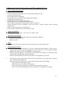
1. Important Safety Instructions and Precaution For Use
•
General Safety Instructions
Do not use the unit near water.
Do not install unit near heating sources and heating emitting devices.
Clean only with dry cloth.
Do not block the fan ventilation.
Prevent the power cord from being walked and/or pinched.
Unplug this unit when not use.
Unplug this unit during lighting and storms.
Do not open the cover of the unit during operation.
Never replace components when the power cable is connected.
Always disconnect power, discharge circuit and remove external voltage before touching
components.
Only use optional accessories with this unit.
Please contact qualified service personnel for repair.
➢
•
Supply Input Range
The unit is of universal input : 100 - 240 VAC, 50Hz / 60Hz .
➢
•
•
•
•
•
•
•
•
•
•
•
Operating environment
The unit is advised be used within the following environment conditions:
• Ambient Temperature: 25C
• Indoor use only.
➢
➢
•
➢
Fuses
For protection of the unit, replace the fuse only with same type and rating of fuse.
Precautions For Use
1.
The unit has a built-in Tracking O.V.P (Over voltage Protection) features. In the event of
output voltage becoming 10% greater than the set value, the O.V.P. will be triggered and the
output power will be cut off and >FAULT< warning appears.
When you get this warning , switch off the unit and remove all loading, switch the unit back
on again and it should resume normal operation.
In the event this problem persists, the unit must be investigated by your agent.
2.
This unit has a buzzer built inside. The buzzer will sound when over temperature/ overload /
over voltage has been triggered.
When you get this warning sound , switch off the unit and remove all loading.
• Check your load and output settings.
• Allow the unit to cool down for 30 minutes.
• If you switch on the unit again, it should resume the normal operation.
• In the event of this problem persists, the unit must be investigate by your agent.
P.1
Warning!
For Model SDP-2603, the maximum output voltage up to 60Vdc.
It may be hazards to touch metal part of the output terminals.
User must avoid touch live metal part of the output terminals.
P.2
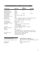
2. Technical Specifications of SDP Series Power Supplies
Specifications
Output Voltage:
Output Current:
Rated Output Power:
Ripple & Noise (p-p):
Load Regulation:
Line Regulation:
Input Voltage:
Maximum Input Power:
Power Factor:
Display Meter:
Meter's Accuracy:
LCD Dimension:
Cooling System:
Operating Temperature:
Protection:
Approvals:
Dimension (WxHxD):
Weight:
Accessory:
Optional Accessory:
Remarks:
SDP-2210
SDP-2603
1-20VDC
1-60VDC
0-10A
0-3.3A
200W
30mVp-p
300mV
200mV
150mV
10mV
100 - 240 VAC, 50Hz / 60Hz
285W
≥0.9
4 digits - display LCD Ammeter, Voltmeter and Power meter
( 1% + 5 counts for range V < 5V, I < 0.5A),
( 1% + 2 counts for range V ≥ 5V, I ≥ 0.5A).
48 x 66 (mm)
Thermostatic Control Fan
0- 40C
-Tracking OVP (Over Voltage Protection),
-Current Limiting,
-Over Temperature Protection.
CE EMC -- EN 55011, CE LVD -- EN 61010
193 x 98 x 215 (mm)
3kg
-User's Manual,
-PC Windows® software, Command Set, LabView® Driver,
-RS-232 cable, RS-485 Connector and one 120ohms Resistor
-RS-232 to RS-485 Adapter ATR-2485
-Adjustable Upper Voltage limit,
-Power Factor Correction.
Remote Programming Specifications
Communications Interface:
Remote Programming Functionality:
Data Logging:
Baud Rate:
Models
SDP-2405
1-40VDC
0-5A
RS-232 (Single Power Supply),
and RS-485 (up to 31 Power Supplies).
Full control of power supply functions and data readback.
Yes, with supplied software.
9600bps
P.3
3. Introduction
The SDP series of Programmable Switching Mode Power Supplies are designed for full remote
programming with data logging functionality. Up to 31 power supplies can be connected via RS485. It is ideal for applications which require various groups of output settings and running periods
for repetitive tests especially with multiple power supplies.
The front panel allows users to all programming and output settings as a stand alone laboratory
power supply.
Full command sets are given in this manual to facilitate the integration of your own control
software.
This series of power supplies have obtained the safety approval EN-61010 and EN-55011 EMC
approval for scientific , industrial equipment of the CE directives.
Please keep this manual in a safe place and contact your vendor for any special requirement in
optional accessories for RS-485.
P.4
4. Controls and Indicators
1
2
Front Panel
3
5
6
4
1. JOG DIAL
2. UP & DOWN KEY
3. DUAL FUNCTION CONTROL KEYS
4. RED COLOR POSITIVE POLARITY OUTPUT TERMINAL
5. BLACK COLOR NEGATIVE POLARITY OUTPUT TERMINAL
6. GREEN COLOR GROUND TERMINAL (connected to chassis)
Back Panel
7
8
10
9
7. POWER SWITCH
8. AC 100-240VAC POWER SOCKET WITH INPUT POWER FUSE
9. RS-232 PORT
10. RS-485 PORT
P.5
5. General Operation Principle
NOTE: This section contains a condensed overview of the unit.
Read this section to quickly get started.
5.1 Quick Reference of Keypad Functions
The front Keypad is organised as follow:
(1) Number Keys, UP/DOWN Keys and Jog Wheel
(2) 4 Dual Function Control Keys
The front panel functions are summarized as follow:
Keypad
Function
Section
Number Keys, UP/DOWN Keys and Jog Wheel
0 thru
Press to select numerical values
6.2.2
UP
Press to ascend the numerical values
6.2.1
DN
Press to descend the numerical values
6.2.1
Rotate to adjust the voltage and current settings
6.2.1
9
Jog Wheel
Dual Function Control Keys
SHIFT
Press to access alternate function of the control keys
CLEAR
Press to terminate any input process and the unit will exit to
normal operation
PROG. 0 thru 9
Press to use programming features.
5.2
Use 0 to recall the timed program
6.3.1
Use 1 thru 9 to specify the location of preset program to be 6.3.3
stored
Use ENTER to confirm
SHIFT
RS-232/485
Press to enter the PC interface selection menu.
6.1.3
You can choose either RS-232 or RS-485
Use RS-232/485 to select RS-232 or RS-485
Use ENTER
RECALL
0 thru 9
to confirm the settings
Press to recall your stored preset or timed program
Use 0 to recall the timed program
6.3.2
Use 1 thru 9 to specify the location of preset program to
recall
6.3.4
Use ENTER to confirm
SHIFT
Lock/Unlock
6.1.2
Press to confirm the new settings
ENTER
SHIFT
Press to Lock/Unlock the Keypad and Jog Wheel
O/P on/off
Press to Enable/Disable the output
6.1.1
P.6
Keypad
Function
Section
SHIFT
UP
Press to Enable the output at power up
6.1.5
SHIFT
DN
Press to Disable the output at power up
6.1.5
SPECIAL Function
SHIFT
Press to get to the Upper Voltage Limit Setting
0
6.1.4
Use 0 thru 9 to input the numerical values
Use
ENTER to confirm
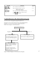
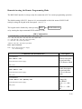
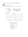
5.2 Quick Reference of The Timed and Preset Program
The unit can store 10 programs (program number 0-9).
Program 0 is reserved for storing 20 steps (Timed Subprograms).
Program 1 to 9 is for 9 sets of preset voltage and current.
Please refer to Figure 5.2 for the structure.
Programming Features
Program 1 - 9
Program 0
Timed Program
Preset Program
The timed program can store
20 steps (timed subprograms)
9 sets of preset voltage and current
Timed Subprogram
Each subprogram is capable of
storing 1 second to 99 minutes
operation period.
The timed program can run
repeatedly 1 to 9999 cycles or
infinite cycles (“0”).
Figure 5.2 Block Diagram of Timed and Preset Program
P.7
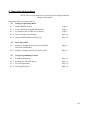
6. Operating Instructions
NOTE: This section shows how to perform power supply functions
using the front panel.
Operations that you can perform are:
6.1 Setting of Operating Mode
6.1.1 Enable/Disable Output
Page 9
6.1.2 Lock/ Unlock the Keypad and Jog Dial
Page 9
6.1.3 PC Interface RS-232/RS-485 Selection
Page 9
6.1.4 Upper Voltage Limit Setting
Page 10
6.1.5 Output Enable/Disable at Power Up
Page 10
6.2
Basic Operation
6.2.1 Setting of Voltage and Current by Jog Wheel
and UP & DOWN Key
Page 11
6.2.2 Setting of Voltage and Current by Key Pad
Page 11
6.3
Using Programming Features
6.3.1 Timed Programming
Page 12
6.3.2 Running the Timed Program
Page 13
6.3.3 Preset Programming
Page 14
6.3.4 Selecting the Preset
Page 14
P.8
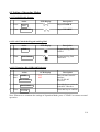
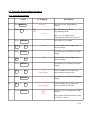
6.1 Setting of Operating Modes
6.1.1 Enable/Disable Output
Action
1.
Press
2.
Then
LCD Display
Description
Output ENABLE
Shift
Output DISABLE
O/P On/Off
6.1.2 Lock/ Unlock the Keypad and Jog Dial
Action
1.
Press
2.
Then
LCD Display
Description
Keypad and Jog Dial
Locked
Shift
Keypad and Jog Dial
UnLocked
Lock/Unlock
6.1.3 PC Interface RS-232/RS-485 Selection
Action
1.
Press
then
SHIFT
RS-232/485
LCD Display
--- 232
485
Description
This will enter into PC
Interface
RS-232/RS-485
Selection.
2.
Press
RS-232/485
Press this key to select the
desired PC Interface
3.
Press
ENTER
Press this key to confirm
Note: Whenever to terminate the settings of Operation Mode, press “CLEAR” to return to normal
operation.
P.9
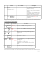
6.1.4 Upper Voltage Limit Setting
Action
1. Press
then
SHIFT
LCD Display
OVER V
25.6
Description
This will enter into Upper
Voltage Limit
Adjustment.
0
In this example, 25.6V is
the present upper voltage
limit.
2.
0
3. Press
to
9
Use the number key to
input your desired voltage
ENTER
Press this key to confirm
Note: Whenever to terminate the Upper voltage Limit Setting, press “CLEAR” to return to normal
operation.
6.1.5 Output Enable/Disable at Power Up
Press
Action
LCD Display
Description
SHIFT
PrUp
This will enable the output
at power up.
i.e. When you switch on
the power supply, the
output is also ON
automatically with last set
voltage value.
ON
then
UP
Press
SHIFT
PrUp
OFF
then
DN
This will disable the output
at power up.
i.e. The output will be OFF
at next power up. This is
the default setting for
safety reason !!
P.10
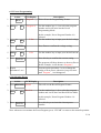
6.2 Basic Operation
6.2.1 Setting of Voltage and Current by Jog Dial and UP & DN Key
Action
1. Press
ENTER
LCD Display
V-set
2. Rotate
3. Press
Sets Voltage
Rotate or Press <UP> &
<DN> Key to set the
voltage level.
or Press
UP &
Description
DN
ENTER
I-set
4. Rotate
Sets Current
Rotate the Jog Wheel or
Press to set the current.
or Press
UP &
5. Press
DN
Press this key to confirm
ENTER
6.2.2 Setting of Voltage and Current Using Keypad
Action
LCD Display
Description
V-set
Press this key to start on
setting voltage.
Use number key to set
the voltage
1.
Press
2.
Press desired voltage
using numbering keypad
from 0
to
9
3.
Press
4.
Press desired current
using numbering keypad
from
to 9
0
Setting current by
pressing number on
Keypad
5.
Press
Press Enter to confirm
voltage and current
settings.
ENTER
ENTER
ENTER
Setting voltage by
pressing numbers on
Keypad.
I-set
Press this key to start on
setting current.
Note: whenever to terminate the settings of voltage and current, press “CLEAR” to return to the
normal operation.
P.11
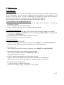
6.3 Using the Programming Features
6.3.1 Timed Programming
Action
1.
Press PROG.
2.
Press
LCD Display
Program
_
StEP
-.-00
0
Description
This will use the Programming
Feature.
This will enter into Timed
Programming Mode.
Program 0
There are 0-19 steps(timed
subprograms) and the first step is 0.
3.
4.
5.
6.
7.
8.
9.
10.
11.
Press ENTER
0
to
9
Press this key to confirm
V-set
Use the number key to input your
desired voltage
Press ENTER
0
to
9
Press this key to confirm the voltage
setting.
I-Set
Use the number key to input your
desired voltage.
Press ENTER
0
to
9
Press this key to confirm the current
setting.
m
Timer 00:00
Press ENTER
0
to
9
Press ENTER
Use the number key to input your
desired minutes in the timer.
Press this key to confirm the minutes
setting.
s
Timer 00:00
StEP
-.-01
Use the number key to input your
desired seconds in the timer.
Press this key to confirm the seconds
setting.
The program will then advance to the
next step. i.e. Step 1
P.12
Action
12.
LCD Display
Description
Repeat
You can repeat procedure 4 to 11 for
setting the next step.
Procedures 4 to 11
Input zero timer period to terminate
the step.
For example, if you want the timed
program to terminate at step 4, just
input zero timer period of step 4.
13.
Press ENTER
Press this key until StEP icon
disappears.
Note: whenever to terminate the Timed Program, press “CLEAR” to return to the normal operation.
6.3.2 Running the Timed Program
Action
LCD Display
1. Press RECALL
2
Press
Recall
_
StEP
-.-00
0
Description
This will use the Recall Program Feature.
This will enter into Recall Timed Program Mode.
Recall 0
3. Press
UP or
4
5.
Press to check the settings of the steps(timed
subprograms)
DN
Press ENTER
1
to
9
Press Enter to confirm
CyC 0000
Use the number key (1-9) to input the number of
running cycles
Recall 0
You can key in 1-9999 cycles.
0000 means the timed program will run infinite
cycles.
6. Press
ENTER
Press this key to activate the timed program.
Note: whenever to terminate the Timed Program, press “CLEAR” to return to the normal operation.
P.13
6.3.3 Preset Programming
Action
LCD Display
1. Press PROG.
Program
2.
Program 4
to
1
9
_
Description
This will use the Programming Feature.
Use the number key (1-9) to select the program
number and it will enter into the Preset
Programming Mode.
In this example, Preset Program Number 4 is
selected.
3.
to
0
4. Press
5.
0
V-Set
9
Press Enter to confirm the voltage setting.
ENTER
to
6. Press
Use the number key to input your desired voltage.
I-Set
9
Use the number key to input your desired current.
Press this key to confirm the current setting.
ENTER
The program will then advance to the next Preset.
In this example, it will advance Program 5
7. Repeat
You can repeat procedure 3 to 6 to change the
setting of next preset, otherwise just press enter
until Program _ icon disappears.
Procedures 3 to 6
6.3.4 Selecting Preset
Action
LCD Display
1. Press RECALL
Recall
2.
Recall 4
1
to
9
_
Description
This will use the Recall Program Feature.
Use the number key (1-9) to select the program
number and it will enter into Recall Preset Mode.
In this example, Preset Program Number 4 is
selected.
3. Press
ENTER
Press this key to activate the chosen preset
number.
Note: whenever to terminate the Preset Program, press “CLEAR” to return to the normal operation.
P.14
7. Maintenance
7.1Recalibration
7.1.1 Introduction
This in-case recalibration is to reduce the difference between the set values and the displayed values
on the LCD Display. You only use the recalibration when the difference is greater than 0.1V for
voltage or 0.01A for current. The whole recalibration for voltages and current takes less than 15
minutes. It is performed by a proprietary software using regression algorithm.
The recalibration software is compatible to window XP, Me, 2000, 98SE, 98.
7.1.2 Installation of the recalibration software
1. In the installation disk, run Setup.exe inside the folder of Re-calibration to install the
recalibration software.
2. Follow the instructions in the setup program.
3. Finally, a SDP Recalibration icon is created in the Program Menu.
7.1.3 Operation Instruction
1. Ensure your PC is Off, connect RS-232 to serial com. port of your PC and the power supply.
2. On your Power Supply, press [SHIFT] key, then quickly press [RS232/485] key and select RS232 followed by [ENTER] key.
3. Switch on your PC and run the SDP recalibration software.
4. Follow the instructions shown in the software.
7.2 Trouble Shooting
1. Keypad and jog dial do not work.
Check key lock symbol, if in Lock state, unlock unit by [SHIFT] then [LOCK/UNLOCK] key.
Otherwise switch OFF unit and switch ON again to see if problem persists.
2. No output power
Check output on/off symbol on display. Otherwise, press [SHIFT] then [O/P ON/OFF].
3. Cannot get high voltage setting within the rated maximum.
Check Upper Voltage Limit setting by [SHIFT] then [0] key.
Reset to rated maximum voltage.
4. CANCEL symbol keeps appearing in all keying in operation.
Keying in time not fast enough as only 10 seconds are allowed for data inputing.
And 3 seconds for operation mode setting. e.g. lock/unlock,output on/off & etc.
5.OUT OF RANGE keeps appearing
A. Check if setting is within the rated range.
B. If this occurs during voltage setting, please refer to point 3.
P.15
8. PC Interface Control User Manual
This section shows how to connect:
– A single power supply via RS-232 Interface
– 2 or above(up to 31) power supplies via RS-485 Interface
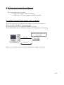
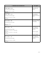
8.1 Connect a Single Power Supply to PC via RS-232
The power supply can be connected to PC via RS-232 as shown in Figure 8.1.
Please use the provided RS-232 connection cable.
The data format is ASCII, no parity bit, 8 data bit, 1 stop bit.
The recommended baud rate is 9600 bps.(Please refer to Appendix B for details)
Connect the RS-232 cable to the
RS-232 port at rear panel of the
Power Supply
RS-232
10m max.
Figure 8.1 Connection between a PC and a Single Power Supply via RS-232.
P.16
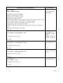
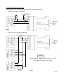
8.2 Connect Multiple Power Supplies to PC via RS-485
For multiple power supplies, use the RS-485 Interface through the RS-485 port at rear panel of the
power supply. Up to 31 power supplies can be connected via RS-485.
You will need a RS-232 to RS-485 Adapter (ATR-2485, Optional Accessory ) and the connection
shown in Figure 8.2a & 8.2b.
RS-232 to RS485 Adapter
2
1
10m max.
31
1000m max.
RS-232 connection
RS-485 connection
Figure 8.2a.
Connection diagram for multiple power supply
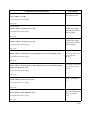
RS485 Connector
Connect to
PC's
RS-232 port
RS-232 to RS485
Adapter , ATR-2485
(optional accessory)
GND
BA+
1
2
31
GND B- A+
GND B- A+
GND B- A+
NOTE
Please connect the provided
120ohm resistors across +A and -B
of RS-485 connectors at the rear of
first and last power supplies.
Figure 8.2b.
120 ohm
Resistor
120 ohm
Resistor
Connection diagram between ATR-2485 Adapter and RS-485
Connectors.
For more informations, please see Appendix B and Appendix C.
P.17
8.3 PC Application Software
8.3.1 What the Application Software will Do
The application software can perform:
– Timed Programming;
– Preset Programming;
– Data Logging;
– Voltage, Current and Upper Voltage Limit Settings.
8.3.2 System Requirements
–
–
–
–
CPU 450 Mhz or above
128 MB Ram
Min. monitor screen resolution: 800 x 600 pixels.
Operating systems: Windows® XP, ME, 2000, 98SE, 98
All brand or trade names are trademarks or registered trademarks of their respective
companies.
8.3.3 Installation of Software
1. Place the provided installation disc in your CD Rom Drive and run setup.exe.
2. Follow the instructions in the setup program.
NOTE
During the running of the setup program, you may encounter “VERSION
CONFICT” remarks, ignore it and click “YES” to complete the installation.
3. A SDP icon is created in the Program Menu.
P.18
8.4 Running the application software for RS-232 Interface
NOTE
Before running the application software, you must have installed and
connected your power supply to the PC using the provided RS-232 cable.
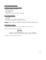
8.4.1 Start-up the Application Software for RS-232
1. Ensure your PC is OFF, connect RS-232 cable to the serial port of your PC and the power supply.
2. On your power supply, press the [SHIFT] key, then quickly press [RS232/485] key and select
RS-232 followed by [ENTER] key.
3. Switch on your PC and run the SDP program.
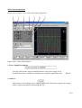
4. Click on Setup, and select the desired COM Port. The default is set at COM 1.
Figure 8.4.1a
5. Click on Supply Connect, then click on Single in the drop menu.
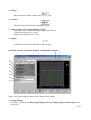
6. An 'Internal Timed Program” Window will appear as shown in Figure 8.4.1b. Click on the Data
Log header on top right and a Data Log Window as shown in Figure 8.4.1c will appear.
Figure 8.4.1b Internal Timed Program Header.
P.19
Figure 8.4.1c Data Log Window
Remarks:
When the right bottom corner of the display window shows the UVL value as shows in Figure
8.4.1d, it indicated that the power supply is connected to PC. The power supply is operating
normally.
Figure 8.4.1d
Figure 8.4.1e
If it shows No Connection as shown in Figure 8.4.1e, check the following:
A) Go back to Setup, check if the correct COM port has beed assigned.
B) Check the power supply if RS-232 has been selected.
C) Check the RS-232 cable connection.
D) Check whether the power supply is ON.
P.20
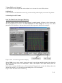
8.4.2 General Operations
Please refer to Figure 8.4.2a for the following descriptions.
Figure 8.4.2a. General Descriptions
1. Power Supply Description:
You may click on the assign an identification for your power supply in use.
Actually this feature is mainly for multiple power supplies application with
RS-485.
2. Address:
This function is for multiple power supplies application. Each power supply has a unique
address. Ignore this function when using RS-232.
P.21
3. Voltage:
Enter the desired output voltage with decimal point.
4. Current:
Enter the desired current limit with decimal point.
5. and 6. Voltage and Current display on LCD
Alternative way to adjust the Output Voltage and Current,
Left click to increase by 0.1 unit;
Right click to decrease by 0.1 unit.
7. Output
Left click on icon will switch ON or OFF the ouput.
8.4.3 Data Logging and Setting Window in Application Software
Figure 8.4.3a Data Logging Function for a Single Power Supply
1. Setting Window
In “Setting” Window, the Data Log Sampling Time and Voltage Upper Limit Setting can be
set by User.
P.22
You can input your desired sample time from 1 second up or select from the drop menu.
You can set your output voltage upper limit value to further safeguard your low voltage
applications.
2. Data Log Window
A. You can use the “Data Log” window to view present output data or stored data.
B. All the parameters at the bottom of the window display can be changed by
direct entry
from the PC (with decimal point) and then confirm by the Enter key of the PC, or select the
values from respective drop menu.
Parameters at the bottom of the Data Log window:
V Min -------- Minimum Voltage Level.
V Max.-------- Maximum Voltage Level.
C Min. -------- Minimum Current Level.
C Max. -------- Maximum Current Level.
W Min. -------- Minimum Power Level in Watt.
W Max. -------- Maximum Power Level in Watt.
3. Log Name
Click cursor on “Untitle”, and type in a name for your log.
4. Log Description
You can type in your detail description of your log.
5. Save Log
a) This function (and the icon) becomes effective when a Log Name is entered
replace the “Untitle”.
b) Click on it will save the current data onto the PC.
c) To retrieve the data, go to the drop menu at (3) Log Name.
6. Export to a File of MS Excel “xls” type
Click on this icon will export the collected data (in the Save Log) in “xls”
to
format to your PC.
P.23
7. Open File Log of “xls type”
Click on this icon will import the collected data in .xls format file to the SDP software.
8. Delete Log
Click on this icon will delete the current log or retrieved log on the display at a current Log Name.
9. Print Log in “xls” Format
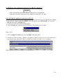
8.4.4 The Time Frame Concept of Data Log
The data logging function starts when the software is started running. In figure 8.4.4a, it shows the
data log in graphical presentation. The Time Minimum and Time Length can be set by Users. Both
parameters are adjustabe so that any time period of the log can be displayed for analysis.
Figure 8.4.4a. The Data Log Window Display
When T Min is set to zero second, it means the unit is on real time and the length of time lapsed is
on the left hand side of the Time Minimum. T Len is the length of time lapsed starting from the
Time Minimum.
In the above example, T Min is set to 320 second and T length to 60 second, the display shows the
output data starting at 320 seconds ago and ending at the 380 second mark.
Figure 8.4.4b The time frame of Data Log
P.24
8.4.5. Internal Timed Program
The PC Interface remote mode really eliminates the tedious process in keying in groups of entries
on the power supply. Because all the data are displayed together in the monitor, possibility of wrong
entry is greatly reduced. Data of different groups can be classified, stored, exported and retrieved for
use at any time.
Furthermore, retrieved data will be in red color if they exceed the preset limits of voltage in Upper
Voltage Level or Current Limiting values.
The operation principle of Saving, Exporting, Filing, Deleting and Printing are the same as the Data
Log Function.
Clear Table........... Delete all data in the Display Table and ready for new data entry.
Save To PS..............Transfer data from Display Table to the Power Supply.
Read Fro PS............Get data from the Power Supply.
Run.........................To run the Timed Program
Running Cycle
Enter the number of desired running cycles here. The maximum cycles is
infinite as “0” cycle is entered.
Operation
1. Clear old data in the power supply by first click [Clear Table] then click [Save To PS].
2. Check if no data in power supply by click [Read Fro PS].
3. Enter data in the table using the 'Up Down Left Right' keys of your PC keyboard for new
locations
4. Data exceed the rated voltage and current will not be accepted.
5. Voltage exceed set UVL (Upper Voltage Limit) will not be accepted.
6. If retrieved or entered data exceed preset Upper or Lower Limit setting of voltage/ current/time,
the data will becomes red in colour.
7. Transfer set data to power supply by clicking [Save to PS].
8. Click [Read Fro PS] to initiate the [Run] Command.
9. Set number of desired [Running Cycle] and click [Run].
P.25
8.4.6 Internal Preset Memory
The operation principle is the same as Internal Timed Program.
To activate the selected preset values, click on the box of the [Select] column then click [Run].
If retrieved or entered data exceed present Upper or Lower Limit Setting of voltage/current/time, the
colour will become red in colour.
8.5 Running the software using RS-485 Interface
NOTE
Before running the application software, you must have installed and connected your power supplies
to the PC via RS-485 as Figure 8.2a and b on page 16.
1. On your power supplies, press [SHIFT] key, then quickly press [RS-232/485] key and select RS485 followed by [ENTER] key..
2. A 3-digit number will appear. This number is the address asigned to the power supply ad will be
used in the software.
3. Using the keypad to key in the address to assign for each power supply. The range is 001 ~ 031
and each of the power supplies requires an unique address.
4. Switch on your PC and run the SDP program.
5. Click on Setup, and select the desired COM port. The default is set to COM 1.
6. In the tool bar, Click on Supply Connect, then click on Single in the drop menu.
7. An Internal Timed Program Window will appear.
8. By choosing the address in the Address Field (Figure 8.5a) You can input the desired settings for
each power supply as given in Section 8.4.2a on page 20.
Figure 8.5a Address of each Power Supply.
P.26
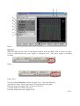
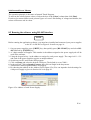
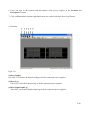
8.5.1 Multi Window Analysis
1. In the tool bar, Click on Supply Connect, then click on Multi in the drop Menu.
2. A Multi Windows Window (Figure 8.5.1a) will appear.
Figure 8.5.1a Multi Window
3. Click on the icon (circled in red in figure 8.5.1a), a Multi Power Supply Connect Setup (Figure
8.5.1b) will appear.
Figure 8.5.1b Multi Power Supply Connect Setup.
4. Click on AutoScan Connect, the window will show the connected power supply indicated as
“Y” as shown in Figure 8.5.1b.
5. Click on the box along the Visible Column to set the desired power supply to be visible in
Multiple Data Log Window.
P.27
6. Users can type in the location and description of the power supplies in the Location and
Description Column.
7. Click on Close button (bottom right hand corner) to return to Multiple Data Log Window.
8. Remarks:
Fig 8.5.1c
(1)Show Digital
One click, it will show the digital readings of all the connected power supplies
(2)Show Log
One click, it will show the data log of all the connected power supplies.
(3)Show Digital and Log
One click, it will show both the data log of all the connected power supplies.
P.28
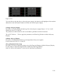
Figure 8.5.1d
You can click on the data log to select the power supply, the data log will highlight in blue and the
address bar in the left bottom window will show the selected power supply.
(3)Single Alleyway Display
One click, it will only display the data log of the selected power supply (Figure 8.5.1e). It will
disable the icon (2), (3) and (4).
The parameters at the bottom are same as the Data Log Window in RS-232 Interface.
The All SP Tick box --- Tick to apply the parameters to all Data Log Window in Multi Alleyway
Display.
(4)Multi Alleyway Display
One click, it will display the Data Log and output data of all power supplies.
It will activate the icon (2), (3) and (4).
(5)Log Thumbnails Size Setup
One click, it let user to adjust the window size of the Data log Window in Multi Alleyway Display.
Use the sliders to adjust the height and the width of the Data Log Window.
Scale 4:3 tick box can enable 4:3 screen size for the Data Log Windows.
P.29
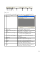
Figure 8.5.1e
The following tables descrbes the function on each Icon as shown in figure 8.5.1e.
Icon
Descriptions
1
Save Log
2
Delete Log
It can delete the log data in the PC.
3
Export to a file Log of xls
type
Click on this icon will export the collected data
(in Data Log) in xls format to your PC.
4
Open File Log of xls type
Click on this icon will import the collected data
in xls format file to the SDP software.
5
Close File Log of xls type
Click on this icon will close the import xls
format file.
6
Print Log
Print Log in xls format.
7
Log
Click on it to select the save log data.
8
Sample
Click on it to select the sampling time.
9
SetV
Click on it and type in to change the voltage
setting of the selected power supply.
10
SetC
Click on it and type in to change the current
setting of the selected power supply.
P.30
APPENDIX A
SDP COMMMAND SET
`
P.31
Remarks in using the Remote Programming Mode
The RS232/485 interface is always ready for connection to PC for remote programming operation .
The default setting is RS-232 , however it is recommended to check the status of RS-232/485
setting by using the keypad at the front panel .( see 6.1.3 ).
The keypad can be disabled by: either pressing SHIFT then LOCK/UNLOCK
or by entering the input command SESS<address> <CR>.
SDP Command Set
{ }- command data, [ ] - return data, [OK] = "OK", [CR] = 0dh
???? = 30h, 30h, 30h, 30h - 39h, 39h, 39h, 39h (4 bytes data)
??? = 30h, 30h, 30h - 39h, 39h, 39h (3 bytes data)
?? = 30h, 30h – 39h, 39h (2 bytes data)
<address> 30h, 30h - 3fh, 3fh (2 bytes data).
Bold – Input Command
Italic – Return Data from Power Supply
PS = Power Supply
Command Code & Return Data
Description
Input Command:
SESS <address> <CR>
Return Data from Power Supply:
Disable front panel
keypad and make
PS to Remote Mode
[OK] [CR]
Input Command:
ENDS <address> <CR>
Return Data from Power Supply:
[OK] [CR]
Enable front panel
keypad and make
PS to exit Remote
Mode
Input Command:
CCOM <address> <RS> {000-255} <CR>
Return Data from Power Supply:
[OK] [CR]
Change RS232/RS485
<RS> = 0 -> RS232
<RS> = 1 -> RS485
P.32
Command Code & Return Data
Description
Input Command:
GCOM <address> <CR>
Return Data from Power Supply:
Get the RS-485
address
[RS] RS485 Address [??] [CR]
[OK] [CR]
Input Command:
GMAX <address> <CR>
Return Data from Power Supply:
Get maximum
voltage and current
of PS
Voltage [???] Current [???] [CR]
[OK] [CR]
Input Command:
GOVP <address> <CR>
Return Data from Power Supply:
Get Upper Voltage
Limit of PS
Voltage [???] [CR]
[OK] [CR]
Input Command:
GETD <address> <CR>
Return Data from Power Supply:
Voltage [????] Current [????] [0] [CR]
[OK] [CR]
Voltage [????] Current [????] [1] [CR]
[OK] [CR]
Get Voltage &
Current reading
from PS
PS in CV mode
PS in CC mode
Input Command:
GETS <address> <CR>
Return Data from Power Supply:
Get Voltage &
Current Set Value
from PS
Voltage [???] Current [???] [CR]
[OK] [CR]
P.33
Command Code & Return Data
Description
Input Command:
Get All Preset
Memory Values
from PS
GETM <address> <CR>
Return Data from Power Supply:
Memory 1 Voltage [???] Current [???]
Memory 2 Voltage [???] Current [???]
.
.
.
.
.
.
.
.
.
.
.
.
Memory 9 Voltage [???] Current [???]
[OK] [CR]
[CR]
[CR]
.
.
.
[CR]
Input Command:
Get Memory from
Specific Preset of
PS
GETM <address> location {1-9} <CR>
Return Data from Power Supply:
Voltage [???] Current [???] [CR]
[OK] [CR]
Input Command:
Get all the Timed
Program Memory of
PS
GETP <address> <CR>
Return Data from Power Supply:
Program 00 Voltage [???] Current [???] Minute [??]
Program 01 Voltage [???] Current [???] Minute [??]
.
.
.
.
.
.
.
.
.
.
.
.
.
.
.
Program 19 Voltage [???] Current [???] Minute [??]
[OK] [CR]
Second [??] [CR]
Second [??] [CR]
.
.
.
.
.
.
Second [??] [CR]
Input Command:
GETP <address> program {00-19} <CR>
Return Data from Power Supply:
Get Timed Program
Memory from
Specific Program of
PS
Voltage [???] Current [???] Minute [??] Second [??] [CR]
[OK] [CR]
P.34
Command Code & Return Data
Input Command:
GPAL <address> [CR]
Description
Get LCD Display
Information
Return Data from Power Supply:
Reading voltage [####] V [ON]
Reading current [####] A [ON]
Reading watt [####] W [ON]
Timer minute [####] second [##] timer [ON] colon [ON] m [ON] s [ON]
Setting voltage [###] V-const [ON] V-bar [ON] V [ON]
Setting current [###] I-Const [ON] I-bar [ON] A [ON]
Program [#] Program [ON] P-bar [ON]
SETTING [ON] Key lock [ON] Key open [ON] FAULT [ON] Output on
[ON]
Output off [ON] Remote [ON] [CR]
[OK] [CR]
Input Command:
VOLT <address> voltage {000-XXX} <CR>
Return Data from Power Supply:
Set Voltage Level
XXX-Max. Output
Rating
Voltage = XX.X V
Current = X.XX V
[OK] [CR]
Input Command:
CURR <address> current {000-XXX} <CR>
Set Current Level
Return Data from Power Supply:
[OK] [CR]
Input Command:
SOVP <address> voltage {000-XXX} <CR>
Set Upper Voltage Limit
of PS
Return Data from Power Supply:
[OK] [CR]
Input Command:
SOUT <address> 1 <CR>
Disable Output of PS
Return Data from Power Supply:
[OK] [CR]
P.35
Command Code & Return Data
Description
Input Command:
SOUT <address> 0 <CR>
Enable Output of PS
Return Data from Power Supply:
[OK] [CR]
Input Command:
POWW <address> location {1-9}0 <CR>
Return Data from Power Supply:
Enable the output
when switch on the
power supply.
[OK] [CR]
Input Command:
POWW <address> location {1-9}1 <CR>
Return Data from Power Supply:
Disable the output
when switch on the
power supply.
[OK] [CR]
Input Command:
PROM <address> location {1-9} Voltage {000-XXX} Current {000-XXX} <CR>
Return Data from Power Supply:
Set Voltage and Current
values of Preset
Memory
[OK] [CR]
Input Command:
PROP <address> location {00-19} Voltage {000-XXX} Current {000-XXX} Minute
{00-99} Second {00-59} <CR>
Set Voltage, Current and
Time period of Timed
Program
Return Data from Power Supply:
[OK] [CR]
Input Command:
RUNM <address> location {1-9} <CR>
Recall Preset Memory
1-9
Return Data from Power Supply:
[OK] [CR]
Input Command:
RUNP <address> times {000-999} <CR>
Return Data from Power Supply:
Run Timed Program
(000 = run infinite
times)
[OK] [CR]
P.36
Command Code & Return Data
Description
Input Command:
STOP <address> <CR>
Stop Timed Program
Return Data from Power Supply:
[OK] [CR]
SDP Command Set REV1.2-- 10/2004
P.37
APPENDIX B
RS-232 CABLE AND CONNECTION INFORMATION
P.38
APPENDIX B RS-232 CABLE AND CONNECTORS INFORMATION
Remark
- The line buffer is assumed to be 16 bytes long.
- The serial asynchronous framing format: no parity bit ,8 data bit, 1 stop bit & bit rate:9600bps
P.39
APPENDIX C
OPTIONAL RS-232 to RS-485 Adapter
ATR-2485
User Manual
P.40
INTRODUCTION
This Adapter is designed for connecting your PC with RS-232 communication port to HALFDUPLEX RS-485 interface programmable power supplies (or other equipment). Its transmission
length can be up to 1000m.
FEATURES & BENEFITS
¨ No driver software is needed
¨ Can directly connected to male RS-232 communication port of your PC
CONTROL AND PIN ASSIGNMENT
ATR-2485
RS-232 to RS-485 Adapter
(2)
(3) (4) (5)
(1)
Fig.1
(1) RS-232 (Connect to the PC communication port )
(2) RS-485 (Connect to equipment with RS-485 interface)
There are 6 pins, only A+, B- and GND pin are useful.
(3) Pin A+
(4) Pin B(5) Pin GND
SPECIFICATIONS
RS-232 side of the adapter
RS-485 side of the adaptor
Connection Speed
Transmission Length
Dimension
Weight
DB-9 female connector
3-pin connector - pin 1: RS-485 (+A)
pin 2: RS-485 (-B)
pin 3: GND
9600bps
Up to 1000 m
33mm (W) x 17mm (H) x 87mm (D)
40 g
P.41
CONNECTION DIAGRAM
Connect the RS-232 side of ATR-2485 to the PC Communication port.
1. Single Power Supply Connection:
120 ohm
120 ohm
come with ATR-2485
Power Supply
RS-485 Connector
A+
BGND
FIG.2
2. 2 or more power supplies connection:
120 ohm
come with ATR-2485
Power Supply 1
RS-485 Connector
A+
BGND
Power Supply 2
RS-485
2 Connector
NOTE
.
.
.
Please connect a 120ohm resistor across A+ and Bof the First and Last power supply.
Last Power Supply
RS-485 Connector
120 ohm
Fig.3
P.42