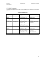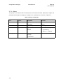
1
HPS-200 HandyPort-Serial User’s Manual 2007. 04. 07 SYM-2200-2E Version 1.0 Copyright SYM-2200-2E HPS-200 User’s Manual Copyright HandyWave Co., Ltd. 202-4 Yatap-dong, Bundang-gu, Seongnam City, Gyunggi Province, 463-070, Republic of Korea Tel: 82-31-709-8900, Fax: 82-31-708-9455, http://www.handywave.com/index3.htm HPS-200, User’s Manual, SYM-2200-2E, Version 1.0, 2007. 04. 07. ii HPS-200 User’s Manual SYM-2200-2E Contents Table of Contents 1. 2. INTRODUCTION .................................................................................................................1-1 1.1. KEY FEATURES ...............................................................................................................1-1 1.2. KEY SPECIFICATIONS ......................................................................................................1-1 1.3. CONTENTS .....................................................................................................................1-1 1.4. RECORD OF CHANGES.....................................................................................................1-2 1.5. ACRONYMS AND DEFINITIONS ..........................................................................................1-2 1.6. REFERENCES .................................................................................................................1-2 HARDWARE SETUP ..........................................................................................................2-1 2.1. GENERAL SPECIFICATIONS ..............................................................................................2-1 2.2. PACKAGE INFORMATION ..................................................................................................2-2 2.2.1. Antenna Port.............................................................................................................2-3 2.2.2. Status Display LED (OPR/LNK) ...............................................................................2-3 2.2.3. Serial Selection Switch (RS-232/RS-422/RS-485)...................................................2-3 2.2.4. Configuration Button (RST) ......................................................................................2-3 2.3. CONNECTION OVERVIEW FOR POWER AND SERIAL INTERFACES ........................................2-3 2.3.1. Power........................................................................................................................2-3 2.3.2. RS-232......................................................................................................................2-4 2.3.2.1. Flow Control Support .....................................................................................2-4 2.3.2.2. Connection Diagrams ....................................................................................2-4 2.3.3. RS-422......................................................................................................................2-5 2.3.4. RS-485......................................................................................................................2-6 3. 2.4. MOUNTING METHOD .......................................................................................................2-7 2.5. QUICK INSTALLATION GUIDE ............................................................................................2-7 CONFIGURATION CHANGING..........................................................................................3-1 3.1. HYPERTERMINAL SETTINGS ............................................................................................3-1 3.2. SWITCH LOCATION ..........................................................................................................3-1 3.3. START CONFIGURATIONS ................................................................................................3-1 3.4. USAGE PRINTING ............................................................................................................3-2 3.5. END CONFIGURATIONS....................................................................................................3-2 3.6. FREQUENTLY USED COMMANDS ......................................................................................3-2 3.7. COMMAND SET ...............................................................................................................3-3 3.7.1. Connection Configuration .........................................................................................3-3 3.7.2. Serial Configuration ..................................................................................................3-4 iii Contents SYM-2200-2E HPS-200 User’s Manual 3.7.3. WAIT Commands .....................................................................................................3-5 3.7.4. Others .......................................................................................................................3-6 Table TABLE 1-1 RECORD OF CHANGES...................................................................................................1-2 TABLE 1-2 ACRONYMS AND DEFINITIONS ........................................................................................1-2 TABLE 2-1 GENERAL SPECIFICATIONS ............................................................................................2-1 TABLE 2-2 PACKAGE INFORMATION ................................................................................................2-2 TABLE 2-3 PIN ASSIGNMENT OF POWER .........................................................................................2-3 TABLE 2-4 PIN ASSIGNMENT OF RS-232 ........................................................................................2-4 TABLE 2-5 PIN ASSIGNMENT OF RS-422 ........................................................................................2-5 TABLE 2-6 PIN ASSIGNMENT OF RS-485 ........................................................................................2-6 TABLE 3-1 FREQUENTLY USED COMMANDS ....................................................................................3-2 TABLE 3-2 CONNECTION CONFIGURATION COMMANDS....................................................................3-3 TABLE 3-3 SERIAL CONFIGURATION COMMANDS .............................................................................3-4 TABLE 3-4 WAIT COMMANDS .........................................................................................................3-5 TABLE 3-5 OTHER COMMANDS ......................................................................................................3-6 Figure FIGURE 2-1 RS-232 CONNECTION DIAGRAM FOR NO FLOW CONTROL ............................................2-4 FIGURE 2-2 RS-232 CONNECTION DIAGRAM FOR HARDWARE FLOW CONTROL ...............................2-4 FIGURE 2-3 RS-232 CONNECTION DIAGRAM FOR END-TO-END FLOW CONTROL .............................2-5 FIGURE 2-4 RS-422 CONNECTION DIAGRAM .................................................................................2-5 FIGURE 2-5 RS-485 CONNECTION DIAGRAM .................................................................................2-6 FIGURE 2-6 WALL MOUNTING FEET ...............................................................................................2-7 FIGURE 3-1 LOCATION OF SERIAL SELECTION SWITCH FOR CONFIGURATION ...................................3-1 iv HPS-200 User’s Manual SYM-2200-2E Introduction 1. Introduction The HPS-200 from HandyWave is a ready-to-use short-range wireless connectivity solution for industrial. It provides the most economic and powerful way of cable replacement for the serial communication systems including RS-232, RS-422, and RS-485. 1.1. Key Features z Supports DIN-RAIL and Wall Mounting z Supports Bluetooth Serial Port Profile and Generic Access Profile z No need of external host and software z Easy of installation and use z Supports configuration of the local device z Supports configuration of the remote device via Over-the-Air z Easy of maintenance z Supports up to 100 meter (Line of Sight) z Supports RS-232, RS-422, and RS-485 z Supports Point-to-Point and Point-to-Multipoint Topology 1.2. Key Specifications z Standard: Bluetooth Specification Version 1.2 and/or above z Operation Frequency: 2.4GHz ISM Band z Transmitted Power: Max 20 / Typical 16dBm (Class 1) z Received Sensitivity: More than –80dBm z Power Supply: DC +5 ~ +30V z Current Consumption: Up to 200mA at DC 5V z Operation Temperature: -20 ~ 60 °C z Dimension: 52.5mm (W) x 86.0mm (D) x 58.0mm (H) z Baud Rate: 1.2, 2.4, 4.8, 9.6, 19.2, 38.4, 57.6, and 115.2Kbps z Antenna Interface: SMA Female z Signal Interface: 14 Terminals and screws 1.3. Contents z HPS 2 EA z Antenna 2 EA z A Quick Start Guide 1-1 Introduction SYM-2200-2E HPS-200 User’s Manual 1.4. Record of changes Table 1-1 Record of changes Revision Date Reason for change 1.0 2007. 04. 07 Original publication of user’s manual (HandyWave reference SYM-2200-2E) 1.5. Acronyms and Definitions Table 1-2 Acronyms and Definitions Acronym Definition ANT Antenna CTS Clear to Send dBm Decibels relative to 1mW DC Direct Current DSR Data Set Ready DTR Data Terminal Ready GND Signal Ground HPS HandyPort-Serial ISM Industrial, Scientific and Medical LNK Link OPR Operation OTA Over the Air RF Radio Frequency RST Reset RTS Request To Send RxD Received Data TxD Transmitted Data 1.6. References 1. HPS-200 Data Sheet, SYD-2200-1E, Version 1.0, 2007. 03. 22., HandyWave 2. How to use 7 Data Bits in HandyPort, AN-2010-12E, 2006. 06. 02., HandyWave 1-2 HPS-200 User’s Manual SYM-2200-2E Hardware Setup 2. Hardware Setup This chapter describes the general specifications and hardware of HPS-200. 2.1. General Specifications The Table 2-1 shows the general specifications of HPS-200. Table 2-1 General Specifications Electrical Characteristics Rating Min Max Storage Temperature -40°C +100°C Operating Temperature -20°C +60°C Supply Voltage: Power +5V +30V Current Consumption N/A 200mA Interface Signal Interface RS-232, RS-422 or RS-485 via 14 Terminals and screws Baud Rate Up to 115.2kbps Supports 1.2/2.4/4.8/9.6/19.2/38.4/57.6/115.2kbps Signals RS-232 TxD, RxD, GND, RTS/DTR, CTS/DSR RS-422 TX+, TX-, RX+, RX-, GND RS-485 TRX+, TRX-, EoR+, EoR-, GND Antenna Interface SMA Female Mounting Interface DIN rail or Wall Mounting (Optional) RF Characteristics Standard Bluetooth Specification Version 1.2 and/or above Frequency 2.400 ~ 2.4835GHz Hopping 1,600/Sec, 1MHz Channel Space Modulation GFSK and/or PSK Tx. Power Max 20 / Typical 16dBm (Class 1) Rx. Sensitivity More than –80dBm Coverage Up to 100 M with supplied antenna (Line of Sight) Others Topology Point-to-Point and Point-to-Multipoint Dimension 52.5mm (W) x 86.0mm (D) x 58.0mm (H) 2-1 Hardware Setup SYM-2200-2E HPS-200 User’s Manual 2.2. Package Information The Table 2-2 shows the package information of HPS-200. Table 2-2 Package Information Items Description Figure ANT An antenna port (SMA Female) OPR/LNK OPR: Shall be on as it’s powered on. (LED) LNK: on – connected, off – not connected, flashing per second – when it’s in setup mode RS-232 A Serial Selection Switch among RS-232, RS- RS-422 422, and RS-485 RS-485 RST Pin # 1 Configuration Button Signal Direction 1 Descriptions TxD O 2 RxD 2 TxD for RS-232 I RxD for RS-232 3 RTS/DTR O RTS/DTR for RS-232 4 CTS/DSR I CTS/DSR for RS- 232 5 GND Common Signal Ground 6 GND Common Power Ground 7 Power I Power Supply 8 TX+/TRX+ I/O TX+: RS-422 TRX+: RS-485 9 TX-/TRX- I/O TX-: RS-422 TRX-: RS-485 10 RX+ I RX+: RS-422 11 RX- I RX-: RS-422 12 GND Common 13 EoR+ O End of Resistor + RS-485 Only 14 EoR- I End of Resistor – RS-485 Only 1 Signal Ground 3 O: Output I: Input 3 End of Resistor: If the HandyPort is required an end of resistor, you can make a loop between EoR+ and EoR-. It is only for RS-485. 2 2-2 HPS-200 User’s Manual SYM-2200-2E Hardware Setup 2.2.1. Antenna Port This is an antenna plug-in port. It is a SMA female type. Therefore, an antenna has to be a SMA male type. 2.2.2. Status Display LED (OPR/LNK) There are OPR and LNK LEDs on HPS-200. The OPR (Operation) LED indicates the status of power. And the LNK (Link) LED indicates the status of RF and setup mode. z OPR LED On: Powered On Off: Powered Off z LNK LED On (Steady): The RF link is on. Off: The RF link is off. Flashing per second: It is in the setup mode. 2.2.3. Serial Selection Switch (RS-232/RS-422/RS-485) You can select a serial interface among the RS-232, RS-422, and RS-485 using the serial selection switch. It is a hardware switch. Therefore, it will be applied right away as soon as it is switched. 2.2.4. Configuration Button (RST) To use the configuration button, the serial selection switch shall be in RS-232 and it is connected to the PC with a terminal emulator like HyperTerminal. You can change the configuration for HPS-200 using this button and command set. 2.3. Connection Overview for Power and Serial Interfaces This section describes the pin assignment for power and serial interfaces. 2.3.1. Power You shall supply power to use the HPS-200. The Table 2-3 shows the pin assignment and specifications for power. Table 2-3 Pin Assignment of Power Pin # Signal Descriptions 6 GND Power Ground 7 Power Power Supply (DC +5V ~ +30V) 2-3 Hardware Setup SYM-2200-2E HPS-200 User’s Manual 2.3.2. RS-232 The HPS-200 supports TxD, RxD, RTS/DTR and CTS/DSR for RS-232 as shown in Table 2-4. To use RS-232, the serial selection switch shall be at RS-232. Table 2-4 Pin Assignment of RS-232 Items Location Switch RS-232 Pin # Signal Direction 1 TxD Output 2 RxD Input 3 RTS/DTR Output 4 CTS/DSR Input 5 GND Common Figure Remarks flow control 2.3.2.1. Flow Control Support The HPS-200 supports two types of flow control. One is Hardware (RTS/CTS) that applies locally (between the HPS-200 and device that is connected to HPS-200). The other is DTR/DSR that applies end-to-end. To use a flow control, you have to configure the HPS-200 accordingly. 2.3.2.2. Connection Diagrams HPS-200 Device Pin # Signal Signal Direction 1 TxD RxD Input 2 RxD TxD Output 5 GND GND Common Figure 2-1 RS-232 Connection Diagram for No Flow Control HPS-200 Device Flow Control: Hardware Flow Control: Hardware Pin # Signal Signal Direction 1 TxD RxD Input 2 RxD TxD Output 3 RTS/DTR CTS or DSR Input 4 CTS/DSR RTS or DTR Output 5 GND GND Common Figure 2-2 RS-232 Connection Diagram for Hardware Flow Control 2-4 HPS-200 User’s Manual SYM-2200-2E Device HPS-200 Hardware OTA Hardware Setup HPS-200 Device Hardware DTR/DSR DTR/DSR RxD 1 TxD 1 TxD RxD TxD 2 RxD 2 RxD TxD CTS/DSR 3 RTS/DTR 3 RTS/DTR CTS/DSR RTS/DTR 4 CTS/DSR 4 CTS/DSR RTS/DTR GND 5 GND 5 GND GND Flow Control Flow Control Figure 2-3 RS-232 Connection Diagram for End-to-End Flow Control 2.3.3. RS-422 The HPS-200 supports TX+, TX-, RX+, and RX- for RS-422 as shown in Table 2-5. To use RS422, the serial selection switch shall be at RS-422. Table 2-5 Pin Assignment of RS-422 Items Location Switch RS-422 Pin # Signal Direction 8 TX+ Output 9 TX- Output 10 RX+ Input 11 RX- Input- 12 GND Common Figure Remarks If required The Figure 2-4 shows an example of the RS-422 connection diagram. The ground signal is an option. HPS-200 Device Pin # Signal Signal Direction 8 TX+ RX+ Input 9 TX- RX- Input 10 RX+ TX+ Output 11 RX- TX- Output 12 GND GND Common Figure 2-4 RS-422 Connection Diagram 2-5 Hardware Setup SYM-2200-2E HPS-200 User’s Manual 2.3.4. RS-485 The HPS-200 supports TRX+, TRX-, EoR+, and EoR- for RS-485 as shown in Table 2-6. To use RS-485, the serial selection switch shall be at RS-485. Table 2-6 Pin Assignment of RS-485 Items Location Switch RS-422 Pin # Signal Direction 8 TRX+ I/O 9 TRX- I/O 12 GND Common 13 EoR+ Output 14 EoR- Input Figure Remarks If required Please see the below. 1 The Figure 2-5 shows an example of the RS-485 connection diagram. The ground signal is an option. And if your device has an end of resistor, you don’t need to make a jumper between EoR+ and EoR- at the HPS-200. HPS-200 Device Pin # Signal Signal 8 TRX+ TRX+ 9 TRX- TRX- 12 GND GND 13 EoR+ 14 EoRFigure 2-5 RS-485 Connection Diagram 1 EoR (End of Resistor): If the HandyPort is required an end of resistor, you can make a loop between EoR+ and EoR-. It is only for RS-485. 2-6 HPS-200 User’s Manual SYM-2200-2E Hardware Setup 2.4. Mounting Method The HPS-200 has a built-in DIN rail interface for mounting. And it supports the wall mounting optionally by wall mounting feet as shown in Figure 2-6. Figure 2-6 Wall Mounting Feet 2.5. Quick Installation Guide Step 1: Assemble a provided antenna to the antenna port on the HandyPort. Step 2: Select a serial interface using the serial selection switch on the HandyPort. Step 3: Make connections using 14 terminals and screws for power and serial interface. Step 4: Configure the HandyPort, if necessary. 2-7 Hardware Setup No text. 2-8 SYM-2200-2E HPS-200 User’s Manual HPS-200 User’s Manual SYM-2200-2E Configuration Changing 3. Configuration Changing This chapter describes how to change the configuration of HandyPort and its command set. To change the configuration for the HandyPort, the serial selection switch shall be at RS-232. And you shall make a connection between the HandyPort and your PC with the RS-232 interface. You may use HyperTerminal or similar terminal emulator to change the configuration for HandyPort. 3.1. HyperTerminal Settings z COM Port Settings: 9600 8-N-1, Flow Control: None (Factory Settings for HandyPort) z Emulation: VT100 3.2. Switch Location To configure the HandyPort, the serial selection switch shall be at RS-232 as shown in Figure 3-1. Figure 3-1 Location of Serial Selection Switch for Configuration 3.3. Start Configurations Step 1: Make a RS-232 connection between the PC and HandyPort. And supply power for HandyPort. Step 2: Open a Hyper Terminal at the PC and set it up. Step 3: Push the RST button on HandyPort. If you enter the configuration mode successfully, LNK LED will be flashing every second. Step 4: Hit the <Enter> key, 5 second later. Step 5: Change the configuration of HandyPort with commands, if necessary. 3-1 Configuration Changing SYM-2200-2E HPS-200 User’s Manual 3.4. Usage Printing If you are in the configuration mode, type “?<Enter>” for listing commands. If you want to know the usage of specific command, type “?[command]<Enter>”. All commands and parameters are case sensitive. Therefore, you have to use the capital letter for commands and parameters. 3.5. End Configurations After finishing the configuration, you have to execute a command “X” to apply changes and exit the configuration mode. 3.6. Frequently Used Commands The Table 3-1 is the list of frequently used commands. Table 3-1 Frequently Used Commands Command Syntax A ABD_ADDR<CR> Change the address of remote device B BBR[D]<CR> Change the baud rate F FFC[D]<CR> Change the flow control M MMode<CR> Change the connection mode P PPA[D]<CR> Change the parity bit S SST[D]<CR> Change the stop bits V V Display the device information 3-2 Description HPS-200 User’s Manual SYM-2200-2E Configuration Changing 3.7. Command Set There are four command groups, that are the connection configuration, serial configuration, wait commands, and others group, for the HandyPort. 3.7.1. Connection Configuration This group of commands is used for changing the connection configuration for HandyPort. The commands are as shown in Table 3-2. Table 3-2 Connection Configuration Commands Item Syntax 1. Remote AAddr<CR> Description 1 address Set a address 2. COM port CCOMPort<CR> Remarks device A remote for a local and remote wireless BD_ADDR always need to connection. be difference. Change a request serial port. COMPort: ‘1’ ~ ‘7’ Only valid in connection mode 2. 3. PIN code EPIN<CR> Authentication Off: hit <Enter> Paired adapters should Authentication On: Type up to 11 have a same PIN code. characters 4. Discovery JE/D<CR> mode Set the discovery mode. Connection mode 1 only. ‘E’: Enable Default: Enable ‘D’: Disable 5. Low Power KE/D<CR> Mode Set the low power mode. Default: Disable ‘E’: Enable ‘D’: Disable 6. Connection MMode<CR> mode Set a connection mode. 0: 1:1 Mode Mode: ‘0’ – ‘3’ 1: WAIT Mode Mode 0 & 2: Required a 2: remote address. REGISTER and CONNECT Mode Mode 2: Required a serial 3: WAIT Command Mode port. 7. Friendly name NName<CR> Set a friendly name up to 11 characters. 8. CoD WCoD<CR> Set the class of device. Default: “001F00” CoD: 6-Hex in ASCII 1 <CR>: Carriage Return (0x0D) 3-3 Configuration Changing SYM-2200-2E HPS-200 User’s Manual 3.7.2. Serial Configuration This group of commands is used for changing the serial configuration of HandyPort. The commands are as shown in Table 3-3. There is a special parameter, ‘D’, for the serial configuration as an option. That is for changing the factory settings of serial configuration. And that is preventing from the remembering the serial settings for changing configuration. There are two serial settings for HandyPort that are “COM Port” and “Factory Settings”. The COM Port is the serial settings for data communication between the HandyPort and device. And the Factory Settings is the serial settings for HandyPort configuration. You can change those settings at once using the option ‘D’. The HandyPort supports 8 data bits only. But you can implement 7 data bits using the HandyPort. Please refer to the document number AN-2010-12E in details. Table 3-3 Serial Configuration Commands Item 1. Baud rate Syntax 1 BBR[D] <CR> Description Remarks Change the baud rate. Baud Rate (BR) - 0: 1200, D (option): Change a 1: 2400, 2: 4800, 3: 9600, 2 factory setting . 4: 19200, 5: 38400, 6: 57600, 7: 115200 2. Flow control FFC[D]<CR> FC - 0: None Set the Flow control. D (option): Change a 1: Hardware 3 3. Parity Bit PPA[D]<CR> 4 5 factory setting . 2: DTR/DSR Set the parity bit. 0: None, 1: Odd 2: Even D (option): Change a 6 factory setting . 45. Stop Bit SST[D]<CR> Set the stop bit. D (option): Change 0: 1 Stop, 1: 2 Stop a 7 factory setting . 1 2 3 4 5 6 7 [D]: An optional parameter. D – It will change the factory settings, too. If you change the factory setting for baud rate, you have to remember it for the future use. If you change a factory setting for flow control, you have to remember it for the future use. This is a flow control between the HPS-200 and device (will not be passed it over the air). This is a flow control for the end-to-end (will be passed it over the air). If you change a factory setting for parity bit, you have to remember it for the future use. If you change a factory setting for stop bit, you have to remember it for the future use. 3-4 HPS-200 User’s Manual SYM-2200-2E Configuration Changing 3.7.3. WAIT Commands This group of commands is used in WAIT command mode only. The commands are as shown in Table 3-4. Table 3-4 Wait Commands Item Syntax 1. Inquiry GTO<CR> Timeout 2. Max number HNO<CR> of search 3. Search device ITO,NO[L]<CR> Description Remarks Set the inquiry timeout. Connection mode 3 only. TO (timeout): ASCII ‘1’ ~ “48” Default: 10 sec. Set the max # response of inquiry. Connection mode 3 only. NO: ASCII ‘1’ ~ “255” Default: 10 Execute searching devices. Connection mode 3 only. TO: ASCII ‘0’ ~ “48” ‘,’: ASCII 0x2C NO: ASCII ‘0’ ~ “255” L (option): Display the long form. 4. Connection QTO<CR> Timeout 5. Connect 6. Cancel TAddr[,TO]<CR> U Set the connection timeout. Connection mode 3 only. TO: ASCII ‘1’ ~ “999” Default: 10 sec. Try to make a connection. Connection mode 3 only. Addr: a remote address ‘,’: ASCII 0x2C TO (option): ASCII ‘0’ ~ “999” Default Timeout: 10 sec. Cancel the previous inquiry. Connection mode 3 only. 3-5 Configuration Changing SYM-2200-2E HPS-200 User’s Manual 3.7.4. Others This group of commands used for showing the current status and state, printing the usages, and rebooting the HandyPort to apply the changes. The commands are as shown in Table 3-5. Table 3-5 Other Commands Item Syntax Description 1. View V Display Remarks the device You can find out a software information version. Rebooting 2. Exit X Apply changes. 3. Status Z Display the status of state ‘S’: Idle / ’P’: Pairing / machine. ’C’: Connecting / ’A’: RF on / ’I’: Inquiring 4. Usage ?[C]<CR> Display the command list or usage. C: Command 3-6