1
I/O ScannerMessage Handling
Module
User’s Manual
Table of Contents
Using This Manual . . . . . . . . . . . . . . . . . . . . . . . . . . . . . . .
11
1.0 Important Information for the Reader . . . . . . . . . . . . . . . . . . .
1.1 Manual's Purpose . . . . . . . . . . . . . . . . . . . . . . . . . . . . . . . . .
1.2 Audience . . . . . . . . . . . . . . . . . . . . . . . . . . . . . . . . . . . . . . .
1.3 Terminology . . . . . . . . . . . . . . . . . . . . . . . . . . . . . . . . . . . . .
1.4 Conventions . . . . . . . . . . . . . . . . . . . . . . . . . . . . . . . . . . . . .
1.5 Manual Design . . . . . . . . . . . . . . . . . . . . . . . . . . . . . . . . . . .
1.6 Important Information . . . . . . . . . . . . . . . . . . . . . . . . . . . . . .
11
11
11
12
12
13
13
Introducing the I/O ScannerMessage Handling Module . . .
21
2.0 Chapter Objectives . . . . . . . . . . . . . . . . . . . . . . . . . . . . . . . .
2.1 Looking at the 1775S4B Scanner's Front Edge . . . . . . . . . . .
2.1.1 Pass and Fail Indicators . . . . . . . . . . . . . . . . . . . . . . . . . . .
2.1.2 Thumbwheel Switch . . . . . . . . . . . . . . . . . . . . . . . . . . . . . .
2.1.3 I/O Channel Status Indicators . . . . . . . . . . . . . . . . . . . . . . .
2.1.4 Backup Connector . . . . . . . . . . . . . . . . . . . . . . . . . . . . . . .
2.1.5 Channel 5 Connector . . . . . . . . . . . . . . . . . . . . . . . . . . . . .
2.1.6 Terminal Swing Arm . . . . . . . . . . . . . . . . . . . . . . . . . . . . . .
2.2 1775S4B Scanner Features and Functions . . . . . . . . . . . . . .
2.3 Specifications . . . . . . . . . . . . . . . . . . . . . . . . . . . . . . . . . . . .
2.4 Chapter Summary . . . . . . . . . . . . . . . . . . . . . . . . . . . . . . . .
21
21
22
22
23
23
23
23
24
24
25
Installing Your 1775S4B Scanner . . . . . . . . . . . . . . . . . . .
31
3.0 Chapter Objectives . . . . . . . . . . . . . . . . . . . . . . . . . . . . . . .
3.1 Inserting Your 1775S4B Scanner . . . . . . . . . . . . . . . . . . . . .
3.2 Using the 1775S4B Scanner's RS232C Channel . . . . . . . . .
3.2.1 Connecting RS232C Devices . . . . . . . . . . . . . . . . . . . . . .
3.2.2 Connecting an Industrial Terminal . . . . . . . . . . . . . . . . . . . .
3.3 Using the 1775S4B Scanner's I/O Terminal Swing Arm . . . . . .
3.4 Chapter Summary . . . . . . . . . . . . . . . . . . . . . . . . . . . . . . . .
31
31
31
31
34
35
38
Operating the LIST Function . . . . . . . . . . . . . . . . . . . . . . .
41
4.0 Chapter Objectives . . . . . . . . . . . . . . . . . . . . . . . . . . . . . . .
4.1 Entering LIST . . . . . . . . . . . . . . . . . . . . . . . . . . . . . . . . . . . .
4.2 Configuring the RS232C Communication Channel . . . . . . . . .
4.2.1 TTY (Printer) Defaults . . . . . . . . . . . . . . . . . . . . . . . . . . . .
4.2.2 CRT Defaults . . . . . . . . . . . . . . . . . . . . . . . . . . . . . . . . . . .
4.2.3 Privileges . . . . . . . . . . . . . . . . . . . . . . . . . . . . . . . . . . . . .
4.2.4 Echo . . . . . . . . . . . . . . . . . . . . . . . . . . . . . . . . . . . . . . . . .
4.2.5 Line Length . . . . . . . . . . . . . . . . . . . . . . . . . . . . . . . . . . . .
4.2.6 Pad Characters . . . . . . . . . . . . . . . . . . . . . . . . . . . . . . . . .
41
41
41
44
44
44
47
47
47
ii
Table of Contents
4.2.7 Tabs . . . . . . . . . . . . . . . . . . . . . . . . . . . . . . . . . . . . . . . . .
4.2.8 Form Feed . . . . . . . . . . . . . . . . . . . . . . . . . . . . . . . . . . . .
4.2.9 Mode . . . . . . . . . . . . . . . . . . . . . . . . . . . . . . . . . . . . . . . .
4.2.10 XON/XOFF . . . . . . . . . . . . . . . . . . . . . . . . . . . . . . . . . . .
4.2.11 Communication Rate . . . . . . . . . . . . . . . . . . . . . . . . . . . .
4.2.12 Parity . . . . . . . . . . . . . . . . . . . . . . . . . . . . . . . . . . . . . . .
4.2.13 Stop Bits . . . . . . . . . . . . . . . . . . . . . . . . . . . . . . . . . . . . .
4.2.14 Data Bits Per Character . . . . . . . . . . . . . . . . . . . . . . . . . .
4.2.15 ASCII Code Size . . . . . . . . . . . . . . . . . . . . . . . . . . . . . . .
4.2.16 Reconfigure . . . . . . . . . . . . . . . . . . . . . . . . . . . . . . . . . . .
4.3 Configuring the I/O Communication Channels . . . . . . . . . . . . .
4.3.1 I/O Channel Configuration . . . . . . . . . . . . . . . . . . . . . . . . . .
4.3.1.1 Communication Rate . . . . . . . . . . . . . . . . . . . . . . . . . . . .
4.3.1.2 I/O Chassis Scanning Sequence . . . . . . . . . . . . . . . . . . . .
4.3.2 I/O Rack Group Selection . . . . . . . . . . . . . . . . . . . . . . . . . .
4.3.3 Reconfig and Auto Config . . . . . . . . . . . . . . . . . . . . . . . . . .
4.4 Chapter Summary . . . . . . . . . . . . . . . . . . . . . . . . . . . . . . . .
48
48
48
49
410
410
410
411
411
411
411
412
412
412
414
414
416
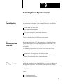
Getting Started in Report Generation . . . . . . . . . . . . . . . . .
51
5.0 Chapter Objectives . . . . . . . . . . . . . . . . . . . . . . . . . . . . . . .
5.1 Introduction . . . . . . . . . . . . . . . . . . . . . . . . . . . . . . . . . . . . .
5.2 Command Line Format . . . . . . . . . . . . . . . . . . . . . . . . . . . . .
5.3 Getting Started . . . . . . . . . . . . . . . . . . . . . . . . . . . . . . . . . . .
5.4 Executing a Simple Procedure . . . . . . . . . . . . . . . . . . . . . . . .
5.5 Executing Procedures from the Message Instruction
in the User Program . . . . . . . . . . . . . . . . . . . . . . . . . . . . . . .
5.6 Control Modes . . . . . . . . . . . . . . . . . . . . . . . . . . . . . . . . . . .
5.7 Chapter Summary . . . . . . . . . . . . . . . . . . . . . . . . . . . . . . . .
51
51
51
52
53
Logical Addressing for Report Generation . . . . . . . . . . . . .
61
6.0 Chapter Objectives . . . . . . . . . . . . . . . . . . . . . . . . . . . . . . .
6.1 Introduction . . . . . . . . . . . . . . . . . . . . . . . . . . . . . . . . . . . . .
6.2 Data Table Addressing . . . . . . . . . . . . . . . . . . . . . . . . . . . . .
6.3 Extended Addressing . . . . . . . . . . . . . . . . . . . . . . . . . . . . . .
6.4 Chapter Summary . . . . . . . . . . . . . . . . . . . . . . . . . . . . . . . .
61
61
61
63
65
Editing a Procedure . . . . . . . . . . . . . . . . . . . . . . . . . . . . . .
71
7.0 Chapter Objectives . . . . . . . . . . . . . . . . . . . . . . . . . . . . . . .
7.1 Editing a Simple Procedure . . . . . . . . . . . . . . . . . . . . . . . . . .
7.2 Entering the Edit Mode . . . . . . . . . . . . . . . . . . . . . . . . . . . . .
7.3 Editing Commands . . . . . . . . . . . . . . . . . . . . . . . . . . . . . . . .
7.3.1 Insert Lines . . . . . . . . . . . . . . . . . . . . . . . . . . . . . . . . . . . .
7.3.2 Set Line Pointer . . . . . . . . . . . . . . . . . . . . . . . . . . . . . . . . .
7.3.3 Advance Line Pointer . . . . . . . . . . . . . . . . . . . . . . . . . . . . .
71
71
73
74
75
76
77
55
57
59
Table of Contents
iii
7.3.4 Backup Line Pointer . . . . . . . . . . . . . . . . . . . . . . . . . . . . . .
7.3.5 Display Line Number . . . . . . . . . . . . . . . . . . . . . . . . . . . . .
7.3.6 Type Out Lines . . . . . . . . . . . . . . . . . . . . . . . . . . . . . . . . .
7.3.7 Searching for Text . . . . . . . . . . . . . . . . . . . . . . . . . . . . . . .
7.3.8 Change Text Characters . . . . . . . . . . . . . . . . . . . . . . . . . . .
7.3.9 Delete Lines . . . . . . . . . . . . . . . . . . . . . . . . . . . . . . . . . . .
7.3.10 Exit Edit Mode . . . . . . . . . . . . . . . . . . . . . . . . . . . . . . . . .
7.4 Editing Messages with a 1775S4A Scanner . . . . . . . . . . . . . .
7.5 Chapter Summary . . . . . . . . . . . . . . . . . . . . . . . . . . . . . . . .
77
78
78
79
710
712
713
713
716
Using Symbols and Expressions in Report Generation . . .
81
8.0 Chapter Objectives . . . . . . . . . . . . . . . . . . . . . . . . . . . . . . .
8.1 Creating and Executing a Simple Procedure with a Symbol . . .
8.2 Symbols . . . . . . . . . . . . . . . . . . . . . . . . . . . . . . . . . . . . . . .
8.3 User Symbols . . . . . . . . . . . . . . . . . . . . . . . . . . . . . . . . . . . .
8.3.1 Assignment Statements . . . . . . . . . . . . . . . . . . . . . . . . . . .
8.3.2 Memory Storage for User Symbols . . . . . . . . . . . . . . . . . . .
8.3.3 User Symbol for Detecting Errors . . . . . . . . . . . . . . . . . . . .
8.4 System Symbols . . . . . . . . . . . . . . . . . . . . . . . . . . . . . . . . . .
8.4.1 Symbol Table . . . . . . . . . . . . . . . . . . . . . . . . . . . . . . . . . . .
8.4.2 Memory Storage for System Symbols . . . . . . . . . . . . . . . . .
8.5 Expressions . . . . . . . . . . . . . . . . . . . . . . . . . . . . . . . . . . . . .
8.5.1 Octal/Decimal Values . . . . . . . . . . . . . . . . . . . . . . . . . . . . .
8.5.2 Comparison Operations . . . . . . . . . . . . . . . . . . . . . . . . . . .
8.5.3 Complement Operation . . . . . . . . . . . . . . . . . . . . . . . . . . . .
8.5.4 Bitwise Operations . . . . . . . . . . . . . . . . . . . . . . . . . . . . . . .
8.5.5 Logical Operations . . . . . . . . . . . . . . . . . . . . . . . . . . . . . . .
8.5.6 Shift Operations . . . . . . . . . . . . . . . . . . . . . . . . . . . . . . . . .
8.5.7 Bit Operation . . . . . . . . . . . . . . . . . . . . . . . . . . . . . . . . . . .
8.5.8 Arithmetic Operations . . . . . . . . . . . . . . . . . . . . . . . . . . . . .
8.5.9 Expressions and Logical Addressing . . . . . . . . . . . . . . . . . .
8.6 Chapter Summary . . . . . . . . . . . . . . . . . . . . . . . . . . . . . . . .
81
81
83
84
85
86
87
87
88
89
810
812
812
813
814
814
815
816
817
818
820
Formatting Data in Report Generation . . . . . . . . . . . . . . . .
91
9.0 Chapter Objectives . . . . . . . . . . . . . . . . . . . . . . . . . . . . . . .
9.1 Formatting Input and Output Data . . . . . . . . . . . . . . . . . . . . . .
9.1.1 Specifying a Format . . . . . . . . . . . . . . . . . . . . . . . . . . . . . .
9.1.2 Justifying Margins . . . . . . . . . . . . . . . . . . . . . . . . . . . . . . .
9.1.3 Displaying Data . . . . . . . . . . . . . . . . . . . . . . . . . . . . . . . . .
9.1.4 Specifying a Base Format . . . . . . . . . . . . . . . . . . . . . . . . . .
9.1.4.1 Base Formatting Examples . . . . . . . . . . . . . . . . . . . . . . .
9.1.4.2 String Values . . . . . . . . . . . . . . . . . . . . . . . . . . . . . . . . .
9.2 Using Standard Control Characters . . . . . . . . . . . . . . . . . . . .
9.3 Using Carriage and Cursor Control Characters . . . . . . . . . . . .
9.4 Using Industrial Terminal Control Characters . . . . . . . . . . . . . .
91
91
91
92
93
95
95
96
97
99
912
iv
Table of Contents
9.5 Using the Conversion Table . . . . . . . . . . . . . . . . . . . . . . . . . .
9.6 Chapter Summary . . . . . . . . . . . . . . . . . . . . . . . . . . . . . . . .
913
915
Using Commands in Report Generation . . . . . . . . . . . . . . .
101
10.0 Chapter Objectives . . . . . . . . . . . . . . . . . . . . . . . . . . . . . .
10.1 Commands . . . . . . . . . . . . . . . . . . . . . . . . . . . . . . . . . . . .
10.2 Direct Commands . . . . . . . . . . . . . . . . . . . . . . . . . . . . . . . .
10.2.1 Print . . . . . . . . . . . . . . . . . . . . . . . . . . . . . . . . . . . . . . . .
10.2.2 Directory . . . . . . . . . . . . . . . . . . . . . . . . . . . . . . . . . . . . .
10.2.3 Create . . . . . . . . . . . . . . . . . . . . . . . . . . . . . . . . . . . . . . .
10.2.4 Delete . . . . . . . . . . . . . . . . . . . . . . . . . . . . . . . . . . . . . . .
10.2.5 Copy . . . . . . . . . . . . . . . . . . . . . . . . . . . . . . . . . . . . . . . .
10.2.6 Rename . . . . . . . . . . . . . . . . . . . . . . . . . . . . . . . . . . . . .
10.2.7 Execute . . . . . . . . . . . . . . . . . . . . . . . . . . . . . . . . . . . . . .
10.3 Indirect Commands . . . . . . . . . . . . . . . . . . . . . . . . . . . . . . .
10.3.1 Print . . . . . . . . . . . . . . . . . . . . . . . . . . . . . . . . . . . . . . . .
10.3.2 Execute . . . . . . . . . . . . . . . . . . . . . . . . . . . . . . . . . . . . . .
10.3.3 Case . . . . . . . . . . . . . . . . . . . . . . . . . . . . . . . . . . . . . . . .
10.3.4 Exit . . . . . . . . . . . . . . . . . . . . . . . . . . . . . . . . . . . . . . . . .
10.3.5 Stop . . . . . . . . . . . . . . . . . . . . . . . . . . . . . . . . . . . . . . . .
10.3.6 If . . . . . . . . . . . . . . . . . . . . . . . . . . . . . . . . . . . . . . . . . . .
10.3.7 Goto . . . . . . . . . . . . . . . . . . . . . . . . . . . . . . . . . . . . . . . .
10.3.8 On_error . . . . . . . . . . . . . . . . . . . . . . . . . . . . . . . . . . . . .
10.3.9 Assignment . . . . . . . . . . . . . . . . . . . . . . . . . . . . . . . . . . .
10.3.10 Inquire . . . . . . . . . . . . . . . . . . . . . . . . . . . . . . . . . . . . . .
10.3.11 Delete . . . . . . . . . . . . . . . . . . . . . . . . . . . . . . . . . . . . . .
10.4 Chapter Summary . . . . . . . . . . . . . . . . . . . . . . . . . . . . . . . .
101
101
101
102
102
103
104
105
106
107
108
108
1010
1011
1012
1013
1013
1014
1015
1017
1020
1021
1022
Using Report Generation Functions . . . . . . . . . . . . . . . . . .
111
11.0 Chapter Objectives . . . . . . . . . . . . . . . . . . . . . . . . . . . . . . .
11.1 Report Generation Functions . . . . . . . . . . . . . . . . . . . . . . . .
11.2 Input Access Functions . . . . . . . . . . . . . . . . . . . . . . . . . . . .
11.2.1 Getchar . . . . . . . . . . . . . . . . . . . . . . . . . . . . . . . . . . . . . .
11.2.2 Testchar . . . . . . . . . . . . . . . . . . . . . . . . . . . . . . . . . . . . .
11.2.3 Testline . . . . . . . . . . . . . . . . . . . . . . . . . . . . . . . . . . . . . .
11.3 Format Conversion Functions . . . . . . . . . . . . . . . . . . . . . . .
11.3.1 To_bcd . . . . . . . . . . . . . . . . . . . . . . . . . . . . . . . . . . . . . .
11.3.2 From_bcd . . . . . . . . . . . . . . . . . . . . . . . . . . . . . . . . . . . .
11.4 Chapter Summary . . . . . . . . . . . . . . . . . . . . . . . . . . . . . . . .
111
111
112
113
113
114
115
115
116
116
Table of Contents
v
Execution Time Considerations . . . . . . . . . . . . . . . . . . . . .
121
12.0 Chapter Objectives . . . . . . . . . . . . . . . . . . . . . . . . . . . . . .
12.1 Introduction . . . . . . . . . . . . . . . . . . . . . . . . . . . . . . . . . . . .
12.2 Active I/O Channels . . . . . . . . . . . . . . . . . . . . . . . . . . . . . .
12.3 Address Complexity . . . . . . . . . . . . . . . . . . . . . . . . . . . . . .
12.4 Symbol Order . . . . . . . . . . . . . . . . . . . . . . . . . . . . . . . . . . .
12.5 Assignment Values . . . . . . . . . . . . . . . . . . . . . . . . . . . . . . .
12.6 Command Line Comments . . . . . . . . . . . . . . . . . . . . . . . . .
12.7 Chapter Summary . . . . . . . . . . . . . . . . . . . . . . . . . . . . . . . .
121
121
121
122
122
122
122
123
Using a Peripheral Communication Module . . . . . . . . . . . .
A1
A.0 Appendix Objectives . . . . . . . . . . . . . . . . . . . . . . . . . . . . . . .
A.1 Introduction . . . . . . . . . . . . . . . . . . . . . . . . . . . . . . . . . . . . .
A.2 Modifying Your Report Generation Procedures . . . . . . . . . . . .
A.2.1 Abbreviating Commands . . . . . . . . . . . . . . . . . . . . . . . . . .
A.2.2 Abbreviating Modifiers . . . . . . . . . . . . . . . . . . . . . . . . . . . .
A.2.3 Abbreviating Functions . . . . . . . . . . . . . . . . . . . . . . . . . . . .
A.2.4 Specifying Octal Addresses . . . . . . . . . . . . . . . . . . . . . . . .
A.2.5 Using the .EQ. Expression Operator . . . . . . . . . . . . . . . . . .
A.2.6 Formatting Data . . . . . . . . . . . . . . . . . . . . . . . . . . . . . . . . .
A.2.7 Suppressing the Line Feed . . . . . . . . . . . . . . . . . . . . . . . . .
A.3 Bit Shift Operation . . . . . . . . . . . . . . . . . . . . . . . . . . . . . . . .
A.4 Form Feed Selection in LIST . . . . . . . . . . . . . . . . . . . . . . . . .
A1
A1
A1
A2
A2
A3
A3
A3
A3
A4
A5
A7
Floating Point Values on the 1775S4B Scanner . . . . . . . . .
B1
B.0 Appendix Objectives . . . . . . . . . . . . . . . . . . . . . . . . . . . . . . .
B.1 Introduction . . . . . . . . . . . . . . . . . . . . . . . . . . . . . . . . . . . . .
B.2 Program Explanation . . . . . . . . . . . . . . . . . . . . . . . . . . . . . .
B1
B1
B2
Report Generation Quick Reference Guide . . . . . . . . . . . .
C1
C.0 Quick Reference . . . . . . . . . . . . . . . . . . . . . . . . . . . . . . . . .
C1
Glossary . . . . . . . . . . . . . . . . . . . . . . . . . . . . . . . . . . . . . .
D1
Chapter
1
Using This Manual
1.0
Important Information for
the Reader
Read this chapter before you use the I/O Scanner-Message Handling
Module (cat. no. 1775-S4B). It tells you how to use the Reader this manual
properly and efficiently for the tasks you will have to perform.
1.1
Manual's Purpose
This manual shows you how to install and operate your I/O
scanner-message handling module. The operation of this module is divided
into two topics:
Using the I/O scanner-message handling module to communicate with
bulletin 1771 I/O chassis
Using the I/O scanner-message handling module’s report generation
capability
1.2
Audience
Before you read this manual or attempt to use the I/O scanner-message
handling module, you should be familiar with the basic operation of the
PLC-3 controller. If you are not familiar with the PLC-3 controller, refer to
the following publications:
PLC-3 Programmable Controller Installation and Operations Manual
(publication 1775-6.7.1, formerly 1775-800)
PLC-3 Controller Programming Manual (publication 1775-6.4.1,
formerly 1775-801)
You can also use our Publication Index (publication SD499) as a guide to
further information about products related to our I/O scanner-message
handling module. Consult your local Allen-Bradley distributor or sales
engineer for information regarding this publication or any needed
information.
11
Chapter 1
Using this Manual
1.3
Terminology
We refer to certain types of equipment throughout this manual. To make
the manual easier for you to read and understand, we avoid repeating full
product names where possible.
We refer to:
I/O Scanner-Message Handling Module (cat. no. 1775-S4B) as the
1775-S4B scanner
I/O Scanner-Programmer Interface Module (cat. no. 1775-S4A) as the
1775-S4A scanner
Industrial Terminal System (cat. no. 1770-T4) as the industrial
terminal
RS-232-C compatible devices which communicate to the PLC-3
controller through the 1775-S4B scanner, such as the data terminals,
computers, or printers as RS-232-C devices
1.4
Conventions
In this manual, we use certain notational conventions to indicate
keystrokes and items displayed on a CRT or printer:
is used to show keystrokes that you enter from the data
terminal keyboard. The keystrokes appear in blue and may
be enclosed in brackets to indicate a specific key on the
keyboard such as:
[ENTER]
In some cases, rather than specific keystrokes, you may be instructed to
enter a variable. In that case, the variable is printed in blue lower case
letters and enclosed in angle brackets (< >) such as:
<address>
is used to show the 1775-S4B scanner’s response to your
keystrokes such as:
S4B>
We describe any exceptions to these conventions where they occur.
12
Chapter 1
Using this Manual
1.5
Manual Design
This manual is designed with as many as three divisions per page. These
divisions include:
Headings in the left margin describe the contents of the text
Text provides explanations, information, and examples
Figures show displays, hardware, and diagrams
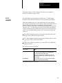
1.6
Important Information
In this manual, there are three different types of important information:
WARNING: Informs you where you could injure yourself if
you do not follow the written procedure.
CAUTION: Informs you where you could damage your
equipment if you do not follow the written procedure.
NOTES inform you of exceptions to the general rules or important
information.
13
Chapter
2
Introducing the I/O ScannerMessage
Handling Module
2.0 Chapter Objectives
This chapter discusses the functions and features of the 1775-S4B scanner.
When you finish reading this chapter, you should:
Be able to identify the hardware components of the 1775-S4B scanner
Know the basic features and functions of the 1775-S4B scanner
2.1
Looking at the 1775S4B
Scanner's Front Edge
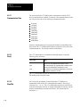
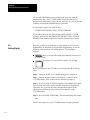
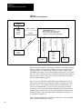
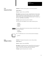
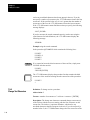
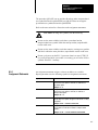
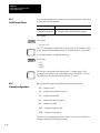
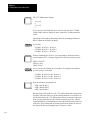
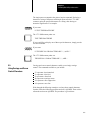
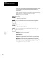
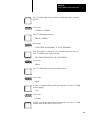
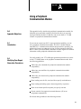
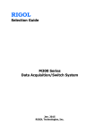
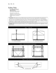
Your 1775-S4B scanner fits into the PLC-3 processor chassis. Looking at
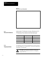
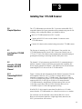
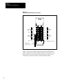
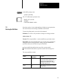
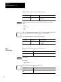
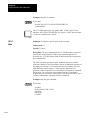
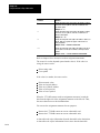
the front edge, you will see the following (figure 2.1):
Pass and Fail indicators
Thumbwheel switch
I/O channel status indicators
Backup connector
Channel 5 connector
Terminal swing arm
These components are described in the following sections.
21
Chapter 2
I/O ScannerMessage Handling Module
Figure 2.1
I/O ScannerMessage Handling Module
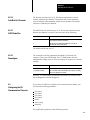
2.1.1
Pass and Fail Indicators
2.1.2
Thumbwheel Switch
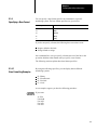
At the top of the 1775-S4B scanner’s front edge, LED indicators labeled
PASS and FAIL keep you informed on the general condition of the
1775-S4B scanner. These indicators have the following meanings:
Pass (green)
Fail (red)
Meaning
On
Off
Normal Operation
Off
On
Module Fault
On
On
Powerup or system reset
Off
Off
PLC3 processor is not on
The thumbwheel switch is below the PASS and FAIL indicators. Setting it
at a unique number (1 to 15) enables the PLC-3 processor to differentiate it
from another 1775-S4B scanner.
CAUTION: Do not change the thumbwheel setting on the
1775-S4B scanner while processor power is on. Equipment
damage could result.
22
Chapter 2
I/O ScannerMessage Handling Module
2.1.3
I/O Channel Status
Indicators
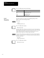
Below the thumbwheel switch are four green LEDs labeled:
CH1
CH2
CH3
CH4
Each LED corresponds to one of the four I/O communication channels.
Each I/O channel can connect to a bulletin 1771 I/O chassis or a group of
chassis providing direct communication with the 1775-S4B scanner. Each
indicator has the following meanings:
If the LED is:
Then:
On
Proper communication exists between
1775S4B scanner and the I/O chassis on the
corresponding I/O channel.
Flashing
A fault exists on one or more of the I/O chassis
on the corresponding I/O channel.
Off
No I/O chassis are connected to the
corresponding I/O channel.
2.1.4
Backup Connector
Below the I/O channel indicators is a connector labeled BACKUP. This
connector is not used.
2.1.5
Channel 5 Connector
Below the backup connector is a 25-pin D-shell connector labeled CH5.
This connector provides communication with an RS-232-C device such as
a data terminal, a computer, or a printer. Refer to chapter 3 for installation
information.
2.1.6
Terminal Swing Arm
Near the bottom of the 1775-S4B scanner is a Terminal Swing Arm (cat.
no. 1775-WA). This swing arm contains the connection terminals for
channels 1 to 4 which scan I/O chassis. We discuss cable connections for
the I/O communication channels in chapter 3.
23
Chapter 2
I/O ScannerMessage Handling Module
2.2
1775S4B Scanner
Features and Functions
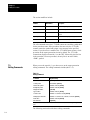
2.3
Specifications
Now that you are aware of the 1775-S4B scanner’s hardware components,
this section summarizes the basic features and functions of the I/O
scanner-message handling module:
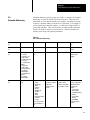
Features
Functions
Four I/O communication
channels
To communicate with I/O Adapter Modules (cat. no. 1771AS) in
I/O chassis. You can connect up to 16 I/O chassis to one
1775S4B scanner I/O channel. The 1775S4B scanner can
communicate with 2,048 inputs and 2,048 outputs per scanner
total.
Report generation channel
To communicate with an RS232C compatible data terminal for
report generation. You can execute messages from your data
terminal or from a MSG instruction in the ladder diagram
program.
Status indicators
To keep you informed on the 1775S4B scanner's status. These
LEDs indicate the general module status and the active state of
each I/O communication channel.
Thumbwheel switch
To distinguish one 1775S4B scanner from another. You can
insert up to 15 1775S4B scanners in one PLC3 system.
Terminal swing arm
To easily connect bulletin 1771 I/O chassis to the 1775S4B
scanner. The terminal swing arm disconnects so you can easily
attach Twinaxial Cable (cat. no. 1770CD). An I/O chassis can
connect to a 1775S4B scanner up to 10,000 cable feet away.
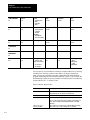
Location
Single slot in a PLC-3 processor chassis
Functions
I/O interface
Report generation
I/O Capacity
2,048 inputs and 2,048 outputs
Channels Per Module
4 I/O communication
1 RS-232-C communication
Communication Rate
57.6 baud or 115.2 kbaud (I/O channel)
110 to 19.2 kbaud (RS-232-C channel)
24
Chapter 2
I/O ScannerMessage Handling Module
I/O Channel Cable Length
10,000 cable feet (max)
Nominal I/O Scan Times
5.5 to 6.5ms for one I/O channel
6ms for two I/O channels
6ms for three I/O channels
6 to 6.5ms for four I/O channels
Backplane Current
2.7A from 5V DC circuit
2mA from +15V DC circuit
2mA from -15V DC circuit
Environmental Conditions
Operational Temperature: 0 to 60° C (32 to 140° F)
Storage Temperature: -40 to 85° C (-40 to 185° F)
Relative Humidity: 5 to 95% (without condensation)
2.4
Chapter Summary
In this chapter, you were introduced to the:
Hardware components on the 1775-S4B scanner
Basic features and functions of the 1775-S4B scanner
Specifications of the 1775-S4B scanner
The next chapters describe installation procedures and PLC-3 LIST
selections for the 1775-S4B scanner.
25
Chapter
3
Installing Your 1775S4B Scanner
3.0
Chapter Objectives
The 1775-S4B scanner provides the PLC-3 processor with an RS-232-C
compatible channel for report generation and a terminal swing arm for I/O
scanning. After reading this chapter, you should be able to:
Insert a 1775-S4B scanner into a PLC-3 system
Connect an RS-232-C device to the channel 5 connector on the
1775-S4B scanner
Connect I/O chassis to the terminal swing arm on the 1775-S4B scanner
3.1
Inserting Your 1775S4B
Scanner
The first step is inserting your 1775-S4B scanner. You can slide the
1775-S4B scanner into any slot of a PLC-3 Processor Chassis (cat. no.
1775-Al, 1775-A2). The chassis electromechanically interlocks helping to
guard against inserting or removing modules while power is on.
3.2
Using the 1775S4B
Scanner's RS232C
Channel
The channel 5, 25-pin connector provides RS-232-C communication to a
modem, computer, or data terminal for report generation capability. We
discuss report generation in chapter 5. The following two sections discuss
connecting RS-232-C devices to the 1775-S4B scanner.
3.2.1
Connecting RS232C
Devices
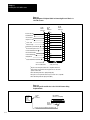
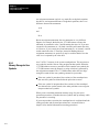
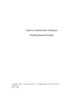
Figure 3.1 shows the pin assignments for the channel 5 connector. You can
use Peripheral Cable (cat. no. 1775-CDC) to connect RS-232-C data
terminals or computers to the 1775-S4B scanner. This peripheral cable is
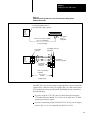
15 feet or 4.6 meters long (figure 3.2). If you need more distance, you can
connect an RS-232-C device up to 50 feet or 15.2 meters from the
1775-S4B scanner by using Remote I/O Interconnect Cable (cat. no.
1778-CR), or equivalent, and two 25-Pin Connector Kits (cat. no.
1770-XXP). Figure 3.3 shows the appropriate wiring.
If an RS-232-C device must be more than 50 cable feet or 15.2 cable
meters from the 1775-S4B module, use a line driver/receiver or a modem.
You could also use the cable that comes with the RS-232-C device.
However, the connector must have a right angle hood; otherwise, the
PLC-3 processor door will not close.
31
Chapter 3
Installing Your 1775S4B Scanner
Figure 3.1
Wiring Diagram of Peripheral Cable for Connecting RS232C Device to
1775S4B Scanner
Protective Ground
1
1
Transmitted Data
2
2
1 Received Data
3
3
2 Request to send
4
4
3 Clear to Send
5
5
3 Data Set
6
6
Signal Ground (Connom Return)
7
7
3 Received Line Signal
8
8
14
14
18
18
Ready
Detector
4 Isolated Transmitted Data
4 Received Data Return
25-Pin
Female
Connector
25-Pin
Male
Connector
25-Pin
Female
Connector
(AA)
1
(BA)
2
(BB)
3
(CA)
4
(CB)
5
(CC)
6
(AB)
7
(CF)
8
14
18
(CD)
20
20
5 Ring Indicator
22
22 (CE)
22
4 Isolated Transmitted Data Return
25
25
25
2 Data Terminal Ready
CH 5 Connector on
the 1775-S4B Scanner
20
Cat. No. 1775-CDC
Cable (15 ft. 4.6m)
1 This pin is for both long line and RS-232-C campatible transmission
2 Signals from the data terminal to these input pins have no effect on the
operation of the module.
3 The module always holds these output pins high (ON).
4 These pins are for long line transmission; they are not RS-232-C compatible.
5 The module always holds this output pin low (OFF).
Figure 3.2
Connecting an RS232C Device to the 1775S4B Scanner Using
Peripheral Cable
I/O Scanner
Message
Handling
Module
(Cat. No.
1775-S4B)
25-Pin
Male
Connector
Data Terminal
(RS-232-C Compatible)
25-Pin
Female
Connector
Cat. No. 1775-CDC Peripheral Cable (15 ft. 4.6m)
32
Chapter 3
Installing Your 1775S4B Scanner
Figure 3.3
Connecting an RS232C Device to the 1775S4B Scanner Using Remote
I/O Interconnect Cable
UserSupplied 25Pin Male Connector;
Cannon Type DB2505, Male or equivalent
I/O Scanner
Message
Handling
Module
(Cat. No.
1775-S4B)
UserSupplied
Connector,
as Appropriate
Cat. No. 1778-CR Cable or equivalent
(50 ft. or 15.2 m maximum)
a) Connection Diagram
UserSupplied
Connector
I/O ScannerMessage
Handling
Module
(Cat. No.
1775-S4B)
7
7
2
2
7
7
3
3
1
1
UserSupplied
Jumpers refer
to section 3.2
UserSupplied Connections
as Appropriate
[AB]
[BA]
[AB]
[BB]
[CB]
[CC]
[CD]
[CF]
7
7
2
2
7
7
3
3
5
5
6
6
20
20
8
8
Data Terminal
(RS232C Compatible)
Cat. No. 1778-CR Cable
or equivalent
50 ft. or 15.2 m
maximum
b) Wiring Diagram
Some RS-232-C devices may require a high signal for a clear to send (CB)
signal at pin 5, a data set ready (CC) signal at pin 6, or a data carrier detect
(CF) signal at pin 8 for proper operation. Depending on your connections,
note the following:
If you are using the 1775-CDC cable to connect directly between the
1775-S4B scanner and the RS-232-C device or its cable, the 1775-S4B
scanner provides these signals.
If you are constructing a cable for the RS-232-C device, you can jumper
pin 20 to pin 5, 6, or 8 as required by the RS-232-C device.
33
Chapter 3
Installing Your 1775S4B Scanner
The RS-232-C device should pull pin 20 high to provide its own signal.
This jumpering is shown by dashed lines in the wiring diagram of
figure 3.3.
3.2.2
Connecting an Industrial
Terminal
You can use the PLC-3 Industrial Terminal Cable (cat. no. 1775-CAT) for
connecting an industrial terminal to the 1775-S4B scanner. Refer to the
steps below for proper connection:
Step 1—Connect the end labeled INDUSTRIAL TERMINAL END to
channel B of the industrial terminal.
Step 2—Connect the end labeled PLC-3 END to the channel 5 connector
on the 1775-S4B scanner.
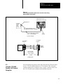
The 1775-CAT cable is 10 feet or 3 meters long (figure 3.4). If you want to
connect the industrial terminal up to 5,000 cable feet (1,524 cable meters)
away from the 1775-S4B scanner, refer to figure 3.5. Use 1778-CR cable
or equivalent cable and two 25-pin male connector kits (cat. no.
1770-XXP).
Figure 3.4
Connecting an Industrial Terminal to the 1775S4B Scanner Using
Industrial Terminal Cable
Industrial Terminal System
(Cat. No. 1770-T1, T2, T3, or T4)
I/O Scannermessage
Handling
Module
(Cat. No.
1775-S4B)
25Pin Male
Connector with
Right-Angle Hood
Cat. No. 1775CAT PLC3
Industrial Terminal Cable (10ft. 3 m)
Channel B
34
Chapter 3
Installing Your 1775S4B Scanner
Figure 3.5
Connecting an Industrial Terminal to the 1775S4B Scanner Using
Remote I/O Interconnect Cable
Industrial Terminal System
(Cat. No. 1770T1, T2, T3, or T4)
RightAngle Hood
I/O Scanner
message
Handling
Module
(Cat. No.
1775-S4B)
User-Supplied 25Pin Male Connector,
Cannon Type DB2505, Male, or equivalent
Cat. No. 1778CR Cable or equivalent
(5000 ft. or 1524m maximum)
Channel B
a) Connection Diagram
UserSupplied
Connector
UserSupplied
Connector
I/O Scanner
Message
Handling
Module
(Cat. No.
1775-S4B)
25
25
25
14
14
2
2
18
18
18
18
3
3
3
3
1
1
25
Industrial
Terminal
Channel B
Cat. No. 1778CR
Cable or equivalent
5000 ft. or 1524 m
maximum
b) Wiring Diagram
3.3
Using the 1775S4B
Scanner's I/O Terminal
Swing Arm
The I/O terminal swing arm provides cable connection for Twinaxial Cable
(cat. no. 1770-CD) which connects to 1771 I/O chassis. This swing arm
contains terminals for I/O channels 1 thru 4. Figure 3.6 shows how to wire
the 1770-CD cable to the terminals on the terminal swing arm.
35
Chapter 3
Installing Your 1775S4B Scanner
Figure 3.6
I/O Scanner Module I/O Channel Connections
Channel
No. 3
Blue
Channel
No. 1
Clear
Line 1
Line 1
Shield
Shield
Line 2
Line 2
Line 1
Line 1
Shield
Shield
Line 2
Line 2
Channel
No. 4
Channel
No. 2
Terminator (Cat. No. 177)
Twinaxial Cable
Cat. No. 1770-CD
Figure 3.7 shows the terminal identification label which indicates the
proper connections for each I/O adapter module to an I/O channel. This
label is on the side of the module. The connections are made at screw
terminals on a wiring arm in front of each I/O adapter module.
36
Chapter 3
Installing Your 1775S4B Scanner
Figure 3.7
I/O Adapter Module (cat. no. 1771AS) Terminal Identification Label
Terminal
Identification
Cat. No. 1771AS
1
Line 1
2
Shield
3
Line 2
4
No connection
5
No connection
6
No connection
7
No connection
8
No connection
9
No connection
10
No connection
11
IN
12
RET
Cable
Reset
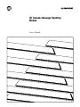
Perform the following steps to make proper I/O channel connections:
Step 1—Connect the twinaxial cable in a serial (daisy chain) fashion from
the 1775-S4B scanner to each I/O chassis within the I/O channel
(figure 3.8).
Step 2—Connect the signal conductor with blue insulation to the LINE 1
terminal at the 1775-S4B scanner and at each I/O adapter module in the
I/O channel.
Step 3—Connect the signal conductor with clear insulation to the LINE 2
terminal. Connect the shield drain wire to the SHIELD terminal.
Step 4—Connect a Terminator (cat. no. 1770-XT) between the terminals at
each end of each I/O channel.
You can optionally connect a normally open, momentary contact switch
between terminals 11 and 12 at each I/O adapter module. You could then
use such a reset switch to reset the I/O adapter module if the PLC-3
processor detects a fault at the I/O chassis. Refer to the PLC-3
Programmable Controller Installation and Operation Manual (publication
1775-6.7.1, formerly 1775-800) for detailed information.
37
Chapter 3
Installing Your 1775S4B Scanner
Figure 3.8
I/O Channel Connections
I/O
Scanner
Module
Swing Arm
(Car. No. 1775-WA)
Terminator
(Cat. No.1770-XT)
ÍÍ
ÍÍ
I/O Adapter
Module Field
Wiring Arm
(Cat. No. 1771-WB)
I/O Adapter
Module Field
Wiring Arm
(Cat. No. 1771-WB)
Twinaxial
Cable
(Cat. No. 1770-CD)
Terminator
(Cat. No. 1770-XT)
Blue
Blue
Blue
Blue
Shield
Clear
Shield
Clear
Shield
Clear
Shield
Clear
Optional
User-supplied
Pushbutton
for I/O Chassis
Restart
Optional
User-supplied
Pushbutton
for I/O Chassis
Restart
ÍÍ
ÍÍ
ÍÍ
10,000 cable ft or
3048 cable m maximum
3.4
Chapter Summary
In this chapter, you read installation procedures for:
Connecting an RS-232-C device to channel 5 for report generation
Connecting I/O chassis to the terminal swing arm for I/O scanning
Before you begin operating the 1775-S4B scanner, we suggest that you
double check all connections.
The next chapter describes LIST selections for the 1775-S4B scanner.
38
Chapter
4
Operating the LIST Function
4.0
Chapter Objectives
The LIST function allows you to select parameters to operate the PLC-3
controller. After reading this chapter, you should be able to:
Select operating parameters for the RS-232-C communication channel
on the 1775-S4B scanner
Select operating parameters for the I/O communication channels on the
1775-S4B scanner
4.1
Entering LIST
You can operate the LIST function for the 1775-S4B scanner through a
1770-T4 terminal or the data access panel on the PLC-3 Main Chassis (cat.
no. 1775-Al). Refer to the PLC-3 Programmable Controller Installation
and Operation Manual (publication 1775-6.7.1, formerly 1775-800) for
detailed information on operating the LIST function.
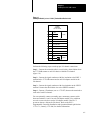
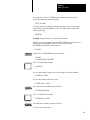
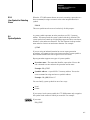
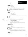
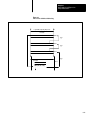
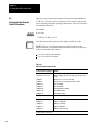
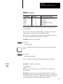
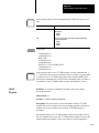
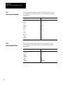
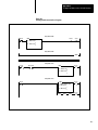
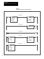
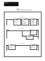
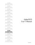
Figure 4.1 shows you the parameters that you can select for each channel.
We explain these parameters in the following sections.
4.2
Configuring the RS232C
Communication Channel
If you select COMM CHAN to configure the RS-232-C communication
channel, you can make the following selections:
TTY (Printer) defaults
CRT defaults
Privileges
Echo
Line length
Pad characters
Tabs
Form feed
Mode
XON/XOFF
Communication rate (baud)
Parity
Stop bits
Data bits/character
ASCII code size
41
Chapter 4
Operating the LIST Function
Reconfig
We explain these selections in the following sections.
42
Chapter 4
Operating the LIST Function
Figure 4.1
LIST Selections for the 1775S48 Scanner
02Chan 5Privileges
3
5
6
I/O Scanner02
Chassis 1 Slot 3
1 Comm Chan
2 I/O Chan
Enter Next>
65
73
Enter Next>
02Comm Chan 5
1 TTY Defaults
2 CRT Defaults
3 Privileges
4 Echo
5 Line Length
6 Pad Char
7 Tabs
8 FF
9 Mode
10 XON/XOFF
11 Baud
12 Parity
13 Stopbits
14 Bits/Char
15 ASCII Code Size
16 Reconfig
Enter Next>
02Chan 5Echo
1 * On
2 Off
Enter Next>
02Chan 5Line Length
Line Length 80
Enter Next>
02Chan 5Pad Char
Pad Char 0
Enter Next>
02Chan 5Tabs
1 * Expanded
2 Not Expanded
Enter Next>
02Chan 5FF
1 Expanded
2 * Not Expanded
Enter Next>
I/O Scanner02I/O Chan
1 I/O Chan 1
2 I/O Chan 2
3 I/O Chan 3
4 I/O Chan 4
5 Racks
6 Auto Config
7 Reconfig
Enter Next>
02I/O Chan 4
1 Baud
2 * I/O Scan
3 Inactive
Enter Next>
02I/O Chan 4Baud
1 57600
2 * 115200
3 Inactive
Enter Next>
02I/O Chan 4Chassis
1 003/2/0
2 005/2/2
3 006/2/6/I
4 005/4/4/I/F
5 007/8/0
Enter Next>
02I/O Racks
1 * 077
2 100177
3 200277
4 300377
Enter Next:
Those selections shown in bold type affect the
operation of the module. The selections not shown
in bold type only cause a movement to another level
of LIST. The LIST display shows an asterisk (*) to
indicate the selection made.
02Chan 5Mode
1 * CRT
2 Print
Enter Next>
02Chan 5XON/XOFF
1 * XON/XOFF
2 No XON/XOFF
Enter Next>
02Chan 5Baud Rate
1
110 Baud
2
150 Baud
3
300 Baud
4
600 Baud
1200 Baud
5
6
1800 Baud
7
2400 Baud
8
4800 Baud
9*
9600 Baud
10
19200 Baud
Enter Next>
02Chan 5Parity
1 Even
2 Odd
3 * None
Enter Next>
02Chan 5Stopbits
1*1
2 1.5
32
Enter Next>
02Chan 5Bits/Char
1*8
27
Enter Next>
02Chan 5ASCII Code Size
18
2*7
Enter Next>
43
Chapter 4
Operating the LIST Function
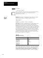
4.2.1
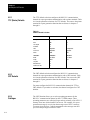
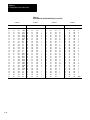
TTY (Printer) Defaults
The TTY defaults selection configures the RS-232-C communication
channel for report generation communication with a printer terminal. Table
4.A lists the parameter selections for TTY defaults. You can use the printer
terminal for report generation functions that we discuss in chapters 5
through 11.
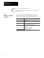
Table 4.A
Channel 5 Default Selections
4.2.2
CRT Defaults
Parameter
TTY Defaults
CRT Defaults
Privileges
3, 5, 6, 65, 73
3, 5, 6, 65, 73
Echo
On
On
Line length
80
80
Pad Char
4
0
Tabs
Expanded
Not Expanded
Form feed
Expanded
Expanded
Mode
Print
CRT
XON/XOFF
XON/XOFF
XON/XOFF
Baud
300 Baud
9600 Baud
Parity
None
None
Stop bits
1
1
Bits/Character
8
8
ASCII Code Size
7
7
The CRT defaults selection configures the RS-232-C communication
channel for report generation communication with a CRT terminal. Table
4.A lists the parameter selections for CRT defaults. You can use the CRT
terminal for report generation functions that we discuss in chapters 5
through 11.
You must configure the RS-232-C communication channel for TTY or
CRT defaults. If you make no selection, the channel configures for CRT
defaults.
4.2.3
Privileges
44
The LIST function allows you to select operating parameters for the
RS-232-C communication channel on the 1775-S4B scanner. These
operating parameters are called privileges and are primarily a list of PLC-3
memory areas into which channel 5 has access. For example, if a report
generation message is to write into the message area of PLC-3 memory,
you must select privilege 5 which corresponds to the message area after
you select the privileges selection in LIST.
Chapter 4
Operating the LIST Function
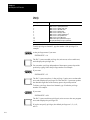
Some privileges, however, do not deal with PLC-3 memory areas. For
example, privilege 65 allows you to edit or delete report generation
messages. Table 4.B lists the available privileges. We describe all the
privileges below:
Privilege 0—System status area. Allows device on channel 5 to write to
the system status area of PLC-3 memory.
Privilege 1—System pointers area. Allows device on channel 5 to write
to the system pointer area of PLC-3 memory.
Privilege 2—Module status area. Allows device on channel 5 to write to
the module status area of PLC-3 memory.
Privilege 3—Data table area. Allows device on channel 5 to write to the
data table area of PLC-3 memory.
Privilege 4—Program area. Allows device on channel 5 to write to the
program area of PLC-3 memory.
Privilege 5—Message area. Allows device on channel 5 to write to the
message area of PLC-3 memory.
Privilege 6—System symbol area. Allows device on channel 5 to write
to system symbol area of PLC-3 memory.
Privilege 7—User symbol area. Allows device on channel 5 to write to
user symbol area of PLC-3 memory.
Privilege 10—Force table area. Allows device on channel 5 to write to
force table area of PLC-3 memory.
Privilege 65—Edit report generation messages. Allows device on
channel 5 to edit or delete report generation messages.
Privilege 73—Accept keyboard input. Allows device on channel 5 to
input data for report generation.
45
Chapter 4
Operating the LIST Function
Table 4.B
Privileges
Privilege Number
Description
0
1
2
3
4
5
6
7
10
65
73
Write access to system status area
Write access to system pointers area
Write access to module status area
Write access to data table area1
Write access to program area
Write access to messages area1
Write access to systems symbols area1
Write access to user symbols area
Write access to force tables area
Edit or delete report generation messages1
Accept keyboard input for report generation1
1 indicates the default privileges.
To add a privilege to channel 5, type the number of the privilege. For
example:
At the privileges menu if you enter:
ENTER NEXT > 10
The PLC-3 processor adds privilege 10 (write access to force table area)
and redisplays the privileges list.
You can make a privilege independent of the memory protect keyswitch
position by typing /I after the privilege number. For example:
If you enter:
ENTER NEXT >3/I
The PLC-3 processor places /1 after privilege 3 (write access to data table
area) and redisplays the privileges list. Then the PLC-3 processor updates
the data table regardless of the memory protect keyswitch position.
To delete a privilege from a local channel, type /D after the privilege
number. For example:
If you enter:
ENTER NEXT > 4/D
The PLC-3 processor deletes privilege 4 (write access to the user program
area) and redisplays the privileges list.
If you do not specify privileges, the default privileges are 3, 5, 6, 65,
and 73.
46
Chapter 4
Operating the LIST Function
4.2.4
Echo
The echo selection determines whether channel 5 immediately transmits
back to the data terminal a copy of each character received from the data
terminal. To enable the echo selection, your RS-232-C device must be set
for full-duplex. Note the following:
If you:
Then:
Select echo
Each keystroke from the data terminal prints out or displays after
being echoed by the channel.
Do not select echo
The keystrokes do not display, unless you can configure the data
terminal to do so directly.
The echo selection defaults to on.
4.2.5
Line Length
You can select a line length value of 0 to 255 characters. If you select a
value of 1 to 255, a new line starts automatically whenever the line length
of a message exceeds the line length value selected.
As an example, consider message text stored with the intention of printing
on a 132-column printer. If an 80-column printer is used, selecting a line
length value of 80 automatically causes a new line to start after 80
characters. This prevents the end of each line from being lost. The default
line length is 80 characters.
If you select value 0, a new line does not automatically start. You can use
the value 0 for many applications involving graphic displays.
4.2.6
Pad Characters
After CR and LF characters are sent to an unbuffered printer to start a new
line, the printer needs some time to position the print head at the start of
the new line. NUL characters follow CR and LF characters to give the
printer this time. Pad characters (1 to 255) provide the number of needed
NUL characters. If no NUL characters are needed, enter a pad characters
value of 0. If you do not specify a pad character, this selection defaults
to 0.
47
Chapter 4
Operating the LIST Function
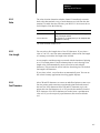
4.2.7
Tabs
The tabs selection determines what the channel transmits for a tab
function:
If you select:
Then:
Not expanded
The channel sends an HT (tab) character in the message
transmission for each HT character in the stored message text.
Sending tab characters is only appropriate when transmitting to a
data terminal which supports a hardware tab function.
Expanded
The channel considers a tab position to exist every 8 columns.
Each time a HT character is reached in the stored message, the
channel sends the number of SP characters to move the cursor
to the next tab position.
The default selection is not expanded.
4.2.8
Form Feed
The form feed selection determines what character or characters the
channel transmits to accomplish the form feed function:
If you select:
Then:
Not expanded
The channel sends a FF character in the transmission for each
FF character in the message text. Sending FF characters is only
appropriate when transmitting to a data which supports a
hardware form feed function.
Expanded
The channel sends seven LF characters in the message
transmission for each FF character in the stored message text.
This selection does not provide a true form feed function, but it
can provide a separation between messages.
The default selection is expanded.
4.2.9
Mode
The mode selection determines what the 1775-S4B scanner does when you
enter a DEL (delete character) from your keyboard. You can make the
following selections:
If you select:
Then:
CRT
A DEL character causes the 1775S4B scanner to send back the
characters BS, SP, BS to erase the character from the screen.
Print
A DEL character causes the 1775S4B scanner to send back the
character being deleted so that it prints again with a slash (/)
character on each side. For example, if you type an E, you would
see it printed as:
E
If you then delete it, you would see:
E/E/
48
Chapter 4
Operating the LIST Function
With either selection, a DEL character deletes the previous character
entered. The default selection is CRT.
4.2.10
XON/XOFF
The XON/XOFF selection determines whether the 1775-S4B scanner
responds to XON and XOFF characters received from the data terminal.
Some data terminals can receive data transmissions at a faster rate than
they can print. They hold the received data in a buffer until the printing can
catch up during the time between transmissions from the module.
However, when a long message is transmitting, this buffer can become full.
Therefore, the 1775- S4B scanner provides an XON/XOFF hand-shaking
function which temporarily inhibits data transmissions until the buffer has
room. To use this hand-shaking function, you can generate the following
characters:
DC3 (XOFF) character generates automatically when the buffer is full
or if you enter [CTRL] S from the keyboard.
DC l (XON) character generates automatically when the buffer is full or
if you enter [CTRL] Q from the keyboard.
CAN (cancel) character generates if you enter [CTRL] X or [BREAK]
from the keyboard.
This selection operates as follows:
If you select:
Then:
XON/XOFF
When the data terminal sends the ASCII character DC3 (XOFF),
the 1775S4B scanner is inhibited from transmitting until it
receives the ASCII character DC1 (XON).
You can use the ASCII character CAN (cancel) to abort the
suspended transmission. The 1775S4B scanner ignores any
other character.
NO XON/XOFF
The 1775S4B scanner does not respond to any DC3 (XOFF)
character received from the data terminal.
The default selection is XON/XOFF.
49
Chapter 4
Operating the LIST Function
4.2.11
Communication Rate
The rate at which the 1775-S4B scanner communicates with RS-232-C
devices connected on its channel 5 connector is the communication or baud
rate. You can select one of the following communication rates:
110 Baud
150 Baud
300 Baud
600 Baud
1200 Baud
1800 Baud
2400 Baud
4800 Baud
9600 Baud
19200 Baud
Select the communication rate by typing the number corresponding to the
desired rate. The 1775-S4B scanner displays an asterisk next to the current
communication rate. The default selection is 9600 Baud.
4.2.12
Parity
The 1775-S4B scanner can communicate through channel 5 using the
following parity selections:
If you select:
Then:
Even
The channel transmits an even parity bit with each character and
checks for an even parity bit in each character received.
Odd
The channel transmits an odd parity bit with each character and
checks for an odd parity bit in each character received.
None
The channel does not transmit a parity bit and does not check for
a parity bit in each character received.
The 1775-S4B scanner displays an asterisk next to the current parity state.
The default parity selection is none.
4.2.13
Stop Bits
410
You can specify the number of stop bits that the 1775-S4B uses to
communicate with its RS-232-C communication channel. The stop bit
selections are 1, 1.5, or 2. The 1775-S4B scanner displays an asterisk next
to the current stop bit selection. To change the number of stop bits, type the
number corresponding to the desired selection. The default stop bits
selection is 1.
Chapter 4
Operating the LIST Function
4.2.14
Data Bits Per Character
The bits/char selections are 7 or 8. The channel transmits the selected
number of data bits per character. The channel only accepts characters
received with the selected number of data bits per character. The default
selection is 8 data bits per character.
4.2.15
ASCII Code Size
The ASCII code size selections are 7 or 8. You use this selection when 8
data bits per character is selected. Then select one of the following:
If you select:
Then:
7
The RS232C communication channel uses the first 7 bits only
in decoding the character transmitted.
8
The RS232C communication channel uses all 8 bits in
decoding the character transmitted.
The default ASCII code size is 7.
4.2.16
Reconfigure
The reconfigure selection implements the channel 5 selections. For
example, if you select CRT defaults, the 1775-S4B scanner does not
implement the change until you select reconfigure. In response to selecting
reconfig:
If channel 5:
Then:
Is not currently executing
The 1775S4B scanner reconfigures the channel immediately.
Is currently executing
The 1775S4B scanner waits until the task completes executing
before it reconfigures the channel.
When the 1775-S4B scanner reconfigures the channel, the asterisk beside
the reconfiguration selection disappears.
4.3
Configuring the I/O
Communication Channels
If you select I/O CHAN to configure an I/O communication channel, you
can select the following parameters:
I/O Chan 1
I/O Chan 2
I/O Chan 3
I/O Chan 4
Racks
Auto Config
Reconfig
We explain these parameters in the following sections.
411
Chapter 4
Operating the LIST Function
4.3.1
I/O Channel Configuration
If you select an I/O channel, you can make the following selections for the
corresponding I/O communication channel:
Communication rate (baud)
I/O scan
We explain these selections in the following sections.
4.3.1.1
Communication Rate
4.3.1.2
I/O Chassis Scanning
Sequence
You can select one of the following communication rates for the
corresponding I/O communication channel:
If you select:
Then:
57.6 kbaud
The maximum I/O channel cable length can be 10,000 feet.
115.2 kbaud
The maximum I/O channel cable length can be 5,000 feet.
You can change the order of execution for an I/O scan of the corresponding
I/O communication channel by selecting the I/O scan selection in LIST.
When you configure an I/O channel for I/O scan, list the I/O chassis in the
order that you want the 1775-S4B scanner to communicate with them. This
allows you to assign a higher priority to some I/O chassis than to others by
listing the higher priority chassis more than once.
As an example, if there are six entries in the I/O chassis list, and entries 1
and 4 are the same, then the chassis listed under entries 1 and 4 will be
updated twice as often as the other chassis. You can list a chassis as often
as you desire, provided that the list contains no more than 32 entries.
Each I/O chassis is listed once in the default configuration at initial
powerup or after an autoconfigure.
When forming the I/O chassis list, remember the following considerations:
Rack numbers which are not assigned consecutively cause greater
memory requirements by allocating memory for unused racks.
No more than 16 I/O adapters can connect to one I/O communication
channel on the 1775-S4B scanner.
No more than 16 different rack numbers can be assigned to one
1775-S4B scanner.
When using complementary or duplicate I/O, two chassis with the same
rack and starting module group numbers must be on different channels
412
Chapter 4
Operating the LIST Function
of the same 1775-S4B scanner. Refer to the PLC-3 Programmable
Controller Installation and Operations Manual (publication 1775-6.7.1,
formerly 1775-800) for detailed information on complimentary and
duplicate I/O.
Rack number 778, is used for internal PLC-3 communication. Do not
assign this number to an I/O rack (although you can use the associated
addresses for internal storage).
Use the following format to enter chassis in the chassis list:
<entry number>/<rack number>/<chassis size>/
<starting module group number>/<attributes >
Entry number defines the position of the entry in the chassis list. For
example, to insert an entry between the third and fourth entries, use entry
number 4. The new entry becomes the fourth entry, and all entries
numbered 4 or greater have their numbers incremented by one.
Rack number is the I/O chassis’ I/O rack number, in octal. The rack
number must be within the range of the rack group selected for the
1775-S4B scanner (refer to section 3.2). The last two digits of the rack
number must correspond to the switch settings on the I/O adapter module
in the I/O chassis.
Chassis size is the number of module groups in the chassis. You can enter:
2 for a 32 I/O chassis
4 for a 64 I/O chassis
8 for a 128 I/O chassis
Starting module group is the lowest numbered module group in the chassis.
It can be 0, 2, 4, or 6.
Attributes can be:
I if the chassis is for inputs only
F if a fault in the chassis is to be considered a major fault
You can have 0, 1, or 2 attributes associated with the chassis.
You can delete entries from the rack list by typing the entry number and
pressing [ENTER]. For example:
To delete the third entry in the rack list, type:
3 [ENTER]
413
Chapter 4
Operating the LIST Function
The 1775-S4B scanner removes the third entry in the rack list and
redisplays the rack list.
An asterisk (*) appearing before an entry in the rack list indicates that the
corresponding I/O chassis or I/O adapter module is faulted.
4.3.2
I/O Rack Group Selection
The I/O rack group selection in LIST selects the range of I/O rack numbers
that the I/O scanner module can address. Presently, the PLC-3 controller
uses only rack number 0 to 768, and the first rack group is selected by
default, so you do not have to make a selection here.
The subscript (8) indicates that the value is expressed in an octal format.
If you plan to use rack numbers greater than 378, consider the following:
Racks numbered greater than 378 increase the I/O scan time.
The amount of memory required for the input and output sections
depends on the highest rack number containing inputs or outputs,
respectively. Therefore, skipping rack numbers is an inefficient use of
memory.
4.3.3
Reconfig and Auto Config
The I/O channel portion of LIST includes selections for reconfig and auto
config. A reconfig implements other changes which you made in LIST. For
example, if you list an I/O chassis three times in the rack list, and you
change the rack list to include that chassis 6 times, the 1775-S4B scanner
does not change its polling sequence until you select reconfig. Reconfig
works for the all the I/O communication channels. Therefore, you can
reconfigure the I/O communication channels once, after making all I/O
channel selections, instead of making separate reconfigure selections for
each I/O channel.
If an asterisk is displayed next to the reconfig selection, change(s) have
been requested but not implemented. Upon selecting reconfig, the
1775-S4B scanner implements the changes and removes the asterisk.
CAUTION: If the PLC-3 processor is in the run mode and
executing block transfers, selecting reconfig could cause a bad
address fault to occur.
414
Chapter 4
Operating the LIST Function
If this situation occurs you should:
Clear the bad fault address in a fault routine
Clear the block transfer bit
Restart the block transfer in the ladder diagram program
Auto config first creates a new I/O chassis list in which each I/O chassis
has equal priority with no attributes assigned. Then a reconfiguration
executes.
The 1775-S4B scanner performs an auto configure at powerup under the
following conditions:
No I/O channel configured for I/O scan has entries in the rack list.
Neither auto configure nor reconfigure has been selected during a
previous powerup (at least since the last time you cleared memory).
When forming the I/O chassis list during an auto configuration, the
1775-S4B scanner polls all valid addresses (rack 0 to 768). If the
1775-S4B scanner receives response to an address, it adds that I/O rack
address to the list. To assign attributes or priorities to the I/O chassis, add
them manually through LIST and reconfigure the I/O channel.
You can only perform an auto configuration when:
PLC-3 processor is in program load mode.
Power is applied to the I/O chassis.
Switch 2 of each I/O chassis is set to “on” to allow the I/O chassis to be
restarted from the PLC-3 processor.
If power is not applied to the I/O chassis, the PLC-3 processor attempts to
perform an auto configuration, and since the I/O chassis does not respond,
the 1775-S4B scanner does not enter it in the I/O chassis list. For an entry
to get into the I/O chassis list in auto config, a valid communication path
must exist between the 1775-S4B scanner and the I/O adapter module for
the I/O chassis.
415
Chapter 4
Operating the LIST Function
4.4
Chapter Summary
In this chapter, you read about PLC-3 LIST selections for the 1775-S4B
scanner. You can access LIST from the PLC-3 front panel or the RS-232-C
channel (channel 5) on the 1775-S4A scanner. Upon selecting the
1775-S4B scanner:
Select COMM CHAN to configure channel 5
Select I/O CHAN to configure an I/O channel
The remainder of this publication describes the 1775-S4B scanner’s report
generation capability. If you do not use this capability, you do not need to
read the remaining chapters.
416
Chapter
5
Getting Started in Report Generation
5.0
Chapter Objectives
The 1775-S4B scanner uses a programming language for report generation
to print or display formatted text and data. After reading this chapter, you
should be able to:
Understand the command line structure
Write and execute a simple procedure
Execute a procedure using the message instruction in a ladder diagram
program
5.1
Introduction
Before you start generating reports with your 1775-S4B scanner, you need
to understand certain key concepts:
Report generation—A programming language that the 1775-S4B
scanner uses to print or display formatted text and data.
Procedure—A collection of report generation command lines that the
1775-S4B scanner uses to generate formatted text and data.
Report—The output generated when a procedure is executed. For
example, shift report, machine status report, or downtime report.
We refer to these terms throughout the discussion of report generation for
the 1775-S4B scanner.
5.2
Command Line Format
The general format for a command line that you will use to generate
reports is:
<command> </modifier> <parameters> <;comment>
The command tells the 1775-S4B scanner what to do. The 1775- S4B
scanner only recognizes one command per command line.
The optional modifier tells the 1775-S4B scanner which way to execute the
command.
The parameters tell the 1775-S4B scanner what data to change.
51
Chapter 5
Getting Started in Report Generation
The optional comment tells someone reading the procedure what the
command line does. The 1775-S4B scanner accepts the semicolon (;)
delimiter as an instruction to ignore the rest of the line. So, you can use the
semicolon to document command lines in a procedure.
As an example, suppose you enter the line:
P ‘FIRST SHIFT PRODUCTION’;TITLE OF REPORT
P is the abbreviation for the print command which tells the 1775-S4B
scanner to print out the data FIRST SHIFT PRODUCTION. TITLE OF
REPORT is the comment which tells what the command line prints out.
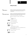
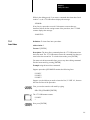
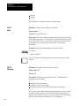
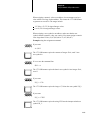
5.3
Getting Started
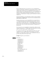
Now that you have been introduced to report generation, let’s do some
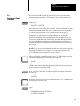
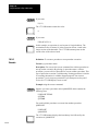
programming. In describing report generation programming, we use the
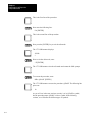
following icons to indicate your action and the 1775-GA module’s
response:
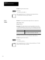
shows your input. The actual input characters are shown in
blue.
shows the 1775-GA module’s response to your input.
Before you program your 1775-S4B, you need to perform the following
steps:
Step 1—Configure the RS-232-C channel through LIST (chapter 4).
Step 2—Connect the data terminal to the channel 5 connector on the
1775-S4B scanner. These connections are described in chapter 3.
Step 3—If you are using an industrial terminal, select alphanumeric mode.
This selection makes the industrial terminal function as a data terminal.
Then make sure you select the same communication options for the
industrial terminal that you selected in LIST for channel 5 on the
1775-S4B scanner.
Step 4—Press [ENTER] or [RETURN]. The terminal displays the prompt:
S4B>
You are now ready to use your 1775-S4B scanner for report generation.
52
Chapter 5
Getting Started in Report Generation
5.4
Executing a Simple
Procedure
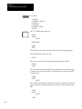
If you have the S4B> prompt on your CRT, you can create and execute
report generation procedures. The first step is to create the procedure by
entering the edit mode.
Simply type:
Ed @TEST1 [ENTER]
ED is the abbreviation for the edit command. The edit command is a report
generation command that enables you to create and store a new procedure
or edit an existing procedure. Also, you may notice that an (@) sign
precedes the first character in the procedure name. The 1775-S4B scanner
interprets an @ sign as a system symbol delimiter and accepts the
characters that follow as the procedure name. Following the @ sign, you
can use up to eight characters to name your procedure. Report generation
accepts any alphanumeric character(s) and the underscore character(s) (_)
for procedure names. Procedures names must start with a letter following
the @ sign.
NOTE: If you are using an industrial terminal to execute report generation
procedures, you cannot use lower case letters to name a procedure as the
industrial terminal does not recognize lower case letters. However, the
1775-S4B scanner does recognize lower case letters.
After you enter the command line above, the 1775-S4B scanner enters the
edit mode by displaying the following lines on the CRT:
<EOB>
*
<EOB> means end of block and signifies that the file, or the memory area
for the procedure is currently empty.
Next, you have to tell the 1775-S4B scanner that you want to insert some
text. So type:
I [ENTER]
When the cursor moves to the line after the asterisk, the 1775-S4B scanner
is ready for you to enter a line.
Type:
P ‘PRINTING ON THE’[ENTER]
P ‘SCREEN’[ENTER]
53
Chapter 5
Getting Started in Report Generation
The 1775-S4B scanner’s line pointer or cursor moves to the next line.
Now exit the insert mode by pressing [ENTER].
The 1775-S4B scanner returns the * signifying the edit mode.
Then press E followed by [ENTER] to exit the edit mode.
The 1775-S4B scanner returns the S4B> prompt. You can now execute
your procedure.
Just type:
S4B> @TEST1
If you followed the instructions, the CRT displays the lines:
PRINTING ON THE
SCREEN
S4B>
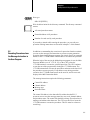
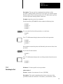
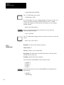
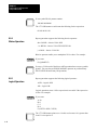
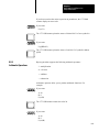
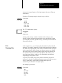
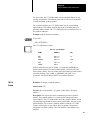
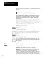
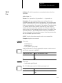
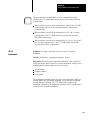
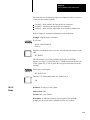
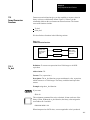
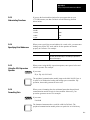
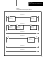
Figure 5.1 summarizes the instructions presented in this section.
Figure 5.1
Creating and Executing a Simple Procedure
S4B> ED @ TEST1
<EOB>
*I
P `PRINTING ON THE'
P `SCREEN'
S4B> @ TEST1
PRINTING ON THE
SCREEN
S4B>
54
Chapter 5
Getting Started in Report Generation
Now type:
S4B> DI [ENTER]
DI is the abbreviation for the directory command. The directory command
returns:
All stored procedure names
Extended address of all procedures
Number of words used by each procedure
If you made a mistake while entering the procedure, you can edit your
procedure. Editing instructions are discussed in chapter 7 of this manual.
5.5
Executing Procedures from
the Message Instruction in
the User Program
In addition to commanding the execution of a procedure from the terminal,
you can use the message send instruction to execute a report generation
procedure from a ladder diagram program. You simply specify an extended
address of the 1775-S4B scanner which enables it to execute the procedure.
When the logic of the rung in the ladder diagram program is true, the Main
Processor Module (cat. no. 1775-LI, L2), or the (CPU), alerts the
1775-S4B scanner to execute the specified procedure. The CPU continues
to scan the rest of the program after alerting the 1775-S4B scanner. The
1775-S4B scanner then executes the procedures and turns on the done bit if
the procedure executes properly. If a problem occurs during procedure
execution, the 1775-S4B scanner turns on the error bit, and an error code
displays in the MSG instruction block.
The message instruction requires the following parameters:
Control file address
Channel address
Message type
Procedure name
The control file address is the data table file address that the PLC-3
processor uses to store the message status bits, error code, channel address,
and procedure name. The control file should be a binary file and can have a
starting word address other than zero. The CPU uses this file to locate the
1775-S4B scanner to execute the procedure. This file must be at least ten
words long.
55
Chapter 5
Getting Started in Report Generation
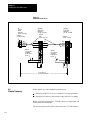
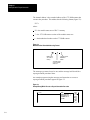
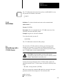
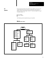
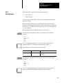
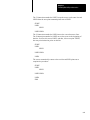
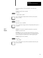
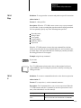
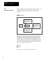
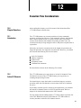
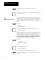
The channel address is the extended address of the 1775-S4B scanner that
executes the procedure. This address has the following format (figure 5.2):
E2.7.t
where:
E2 = the module status area of PLC-3 memory
7 = the 1775-S4B scanner section of the module status area
t = the thumbwheel number on the 1775-S4B scanner
Figure 5.2
MSG Instruction Extended Addressing Format
Module status
area of PLC3
memory
1775S4B scanner
thumbwheel
number
1775S4B scanner
section of module
status area
The message type must always be one, and the message itself should be a
report generation procedure name.
An example program using the message send instruction to execute a
report generation procedure appears in figure 5.3.
Figure 5.3
Example Rung Which Executes a Report Generation Procedure
I0012
12
56
MSG
MESSAGE TYPE
CTL=FB005:0000=
CHANNEL E2.7.1
@TIME
1
0
STAT
(EN)
12
STAT
(DN)
15
STAT
(ER)
13
Chapter 5
Getting Started in Report Generation
5.6
Control Modes
As we have described in this chapter, you can:
Create and execute report generation procedures from the S4B> prompt
Call for procedures to execute from MSG instructions in your ladder
diagram program
The communication that occurs between the RS-232-C device on channel 5
of the 1775-S4B scanner can be in one of two control modes:
Command mode—The data terminal keyboard has direct control over
the operation of the 1775-S4B scanner. When you execute a procedure
at the S4B> prompt, you are in the command mode.
Ladder diagram mode—The ladder diagram program has direct
control over the operation of the 1775-S4B scanner. When a procedure
executes from the MSG instruction to an RS-232-C device connected to
channel 5 on the 1775-S4B scanner, you are in the ladder diagram
mode.
Figure 5.4 shows you the report generation control modes and how to
move from one to another.
57
Chapter 5
Getting Started in Report Generation
Figure 5.4
Report Generation Control Modes
Initialization
Execute
Procedure
•
•
•
•
•
•
Print
Directory
Create
Delete
Copy
Rename
E [RETURN]
ED @<procedure name> [RETURN]
Completed
Direct Command
[RETURN]
Procedure completed
Command Mode in Control
S4B> is output to the data terminal to prompt
the operator upon return to this mode after
completing a command and after each [RETURN].
[BREAK] or [CTRL] [X] or
Print or
Execute
Procedure
[BREAK] or [CTRL] [X]
@ <procedure name> [RETURN]
Procedure completed
MSG Instruction
Ladder
Diagram
Program
in
Control
Edit
Mode
When you turn on your PLC-3 processor it initializes with ladder diagram
mode in control. So if you connect an RS-232-C device to the channel 5
connector on the 1775-S4B scanner, report generation procedures sent
from MSG instructions in your ladder diagram program will execute at the
RS-232-C device. When a procedure completes executing, ladder diagram
mode remains in control. Thus, you can execute consecutive procedures
from the ladder diagram program.
Now if you press [ENTER] or [RETURN] after initialization or after a
message procedure has been executed, the S4B> prompt displays at the
RS-232-C device. This prompt indicates that the command mode is in
control. In command mode, you can execute or edit report generation
procedures or enter report generation commands from your keyboard to
operate report generation. We describe report generation operation in the
following chapters. The report generation commands listed in figure 5.4
are described in chapter 10.
Now if you press [BREAK] or [CTRL] X while you are in the command
mode, the following message displays:
58
Chapter 5
Getting Started in Report Generation
REPORT GENERATION ABORTED
At this point, ladder diagram mode is in control.
If the ladder diagram program calls for the 1775-S4B scanner to execute
report generation commands or procedures while the command mode
controls the 1775-S4B scanner, the 1775-S4B scanner does not respond to
the ladder diagram program immediately. In this case, the 1775-S4B
scanner stores as many as 4 report generation instructions in a ladder
diagram program until the 1775-S4B scanner switches to ladder diagram
control. If the ladder diagram program contains more than 4 report
generation instructions and you switch the 1775-S4B scanner to ladder
diagram mode:
The 1775-S4B scanner executes the first 4 instructions in the order that
they were stored.
The 1775-S4B scanner executes any remaining instruction(s) in random
order.
5.7
Chapter Summary
In this chapter, you were introduced to report generation on the 1775-S4B
scanner. The remainder of the publication describes the various parameters,
commands, and functions used to generate reports on the 1775-S4B
scanner.
59
Chapter
6
Logical Addressing for
Report Generation
6.0
Chapter Objectives
In addition to creating text in procedures, you can use report generation to
manipulate data within a specific area of PLC–3 memory. After reading
this chapter, you should be able to:
Use data table addressing to specify a memory area
Use extended addressing to specify a memory area
6.1
Introduction
Logical addressing for 1775–S4B scanner report generation is similar to
logical addressing for the PLC–3 front panel or the industrial terminal. The
dollar sign ($) delimiter tells the 1775–S4B scanner that the following data
denotes a PLC–3 memory address. You can specify PLC–3 addresses in
two ways:
Data table addresses
Extended addresses
We discuss the formats for each of these logical addressing methods in the
following sections.
6.2
Data Table Addressing
You can specify data table sections of memory by using data table
addressing. In data table addressing, you follow the $ sign with the data
table section specifier. Then you can specify a file, word, and/or bit. Table
6.A shows the data table section specifiers. You must use a colon before
the word number.
You can specify an octal address format for data table addresses by
entering a leading zero in the bit position of the address. Using this format
can make your report generation procedure compatible with ladder
diagram program addressing and I/O terminal numbering. Figure 6.1
shows how the bit numbering formats in report generation correspond to
the bit numbering format within a PLC–3 memory word.
61
Chapter 6
Logical Addressing for Report Generation
Some examples appear below:
Data Table Address
Description
$B1:5
This address specifies binary file, 1, word 5.
$D0:1 or $D:1
These addresses specify the same address, decimal file 0
word 1. If you are specifying file 0, you need not enter a zero
after the section specifier.
$TPRE:57
This address specifies the preset of timer 57.
$B1:5/12
This address specifies binary file 1, word 5, bit 12 decimal.
$B1:5/12 or $B1:5/014
Both addresses specify binary file 1, word 5, bit 12 decimal. In
the second example, 014 represents the octal value for 12. To
enter a value in octal, enter a zero before the value.
Table 6.A
Data Table Section Specifiers
Section Specifier
Extended Address
Data Table Section
O
I
T
C
N
F
D
B
A
H
P
S
3.1.1
3.1.2
3.1.3
3.1.4
3.1.5
3.1.6
3.1.7
3.1.8
3.1.9
3.1.10
3.1.12
3.1.13
Output
Input
Timers
Counters
Integers
Floating Point1
Decimal
Binary
ASCII
High Order Integers
Pointers1
Status
1 You can only access these sections through extended addressing
Figure 6.1
Bit Numbering Formats
For report generation, always enter a leading
zero to maintain the octal addressing format
for compatibility with ladder diagram program
addressing and I/O terminal numbering.
The bit numbering
format within a
PLC3 memory
word address
(ladder diagram
programming).
017 016 015 014 013 012 011 010
07
06
05
04
03
02
01
00
17
16
15
14
13
12
11
10
07
06
05
04
03
02
01
00
15
14
13
12
11
10
9
8
7
6
5
4
3
2
1
0
Alternately, by not entering leading
zeros, bits can be addressed in a
decimal format for report generation
62
Chapter 6
Logical Addressing for Report Generation
6.3
Extended Addressing
Extended addressing can access any area of PLC–3 memory. In extended
addressing, you enter E followed by the memory area. Then you enter
parameters, or levels that the memory area requires, seperated by periods
to specify a memory address to the bit level if necessary. For example, if
you are specifying a data table address, you follow the $ sign with E3 to
specify the data table. Then you must enter a context number, data table
section, file number, structure, word and/or bit. Table 6.B outlines the
memory areas along with required parameters.
Table 6.B
PLC-3 Extended Addressing
SYSTEM STATUS
Context
Section
Word
E0
0
SYSTEM POINTERS
Context
Section
Word
E1
0
0
032767
MODULE STATUS
Module Type
Thumbwheel Switch
Module Data
E2
1 - memory
2 - main processor
3 - I/O scanner
programmer interface
4 - reserved
5 - communication
adapter
6 - expansion
7 - I/O scanner
message handling
8 - peripheral
communication
9 - communication
interface
14 - memory
communication
115
Defines system
attributes
DATA TABLE
Context
Section
File
Structure
Word
E3
115
1 - output
2 - input image
3 - timers*
4 - counters*
5 - integers
6 - floating point
7 - decimal
8 - binary
9 - ASCII
10 - high order integer
12 - pointers*
13 - status
0 for timers, counters,
and pointers.
09999 for timers,
counters, and pointers
077778 for input and
output image tables.
0999 for all other
sections.
0 for all other sections.
For timers and
counters:
0 - control (CTL)
1 - preset (PRE)
2 - accumulator (ACC)
022
* these sections must
have a file number of
zero
For pointers:
0 - section (SEC)
1 - file (FIL)
2 - word (WRD)
09999 for all other
sections
63
Chapter 6
Logical Addressing for Report Generation
USER PROGRAM
Context
Section
Rung
Instruction
Word
E4
115
0 - program status
1 - main
2 - subroutine
3 - faults
032767
032767
032767
MESSAGES
Context
Section
Message
Word
E5
115
1 - report generation
2 - comments
3 - terminal
(MACROS)
4 - data highway
5 - assistance (HELP)
065535
032767
SYSTEM SYMBOLS
Symbol Context
Symbol Type
Number
Word
E6
115
1
032767
032767
FORCE TABLE
Context
Force Type
Rack Number
Word
Bit (force type 0 only)
E10
115
0 - status (no rack
number word must be
0)
1 - forced output
2 - forced input
037
015
0 - input
enable/disable
1 - output
enable/disable
SYSTEM
SCRATCHPAD
E7
CONVERTED
PROCEDURES
E8
You can specify an octal address format for extended addresses by entering
a leading zero in the bit position of the address. Using this format can
make your report generation procedure compatible with ladder diagram
program addressing and I/O terminal numbering. Figure 6.1 shows how the
bit numbering formats in report generation correspond to the bit numbering
format within a PLC–3 memory word.
Some examples appear below:
Extended Address
Description
$E3.1.2.3.0.0
This address translates to the data table (3), context (1), input
image table (2), file (3), structure (0), and word (0).
$E3.1.8.1.0.5 or $B1:5
These addresses specify binary file 1 word 5.
$E0.0.0.17
This address specifies system status area hour storage word.
To access the system status area, you must select privilege 0 in
LIST. Refer to chapter 4 for detailed information on selecting
privileges.
$E3.1.8.0.0.1/10 or
$E3.1.8.0.0.I/O12
64
These addresses specify to bit 10 of the data table area, binary
file 0, word 1, bit 10. The octal value 12 is 10 decimal.
Chapter 6
Logical Addressing for Report Generation
6.4
Chapter Summary
In this chapter, you read about addressing PLC–3 memory areas:
You can use the extended addressing format to specify any location in
PLC–3 memory.
You can use the data table addressing format to specify any section of
the data table.
The next chapter describes editing procedures.
65
Chapter
7
Editing a Procedure
7.0
Chapter Objectives
In chapter 5, you learned how to enter the edit mode to insert a procedure
and execute the procedure at the S4B> prompt. After you read this chapter,
you should be able to use all editing commands available with the
1775-S4B scanner.
7.1
Editing a Simple Procedure
In chapter 5, we created a procedure called @TEST1 and executed it. Now
suppose you want to change the procedure. This section discusses editing a
simple procedure. If you are comfortable with the procedure concept, you
can move on to the next section (section 7.2) of this chapter.
Our procedure called @TEST1 from chapter 5 contains the following
lines:
P ‘PRINTING ON THE’
P ‘SCREEN’
Let’s change the procedure. Type:
S4B> ED @TESTI [ENTER]
This time, the CRT displays the lines:
P ‘PRINTING ON THE’
*
Type the line:
C/PRINTING/PRINT OUT/ [ENTER]
This instruction tells the 1775-S4B scanner to change PRINTING from the
procedure text to PRINT OUT.
So, the 1775-S4B scanner responds with the line:
P ‘PRINT OUT ON THE’
*
Now press [ENTER].
71
Chapter 7
Editing a Procedure
The 1775-S4B scanner displays the next line of the procedure @TEST1:
P ‘SCREEN’
*
Now press [ENTER].
The 1775-S4B scanner displays the lines:
<EOB>
*
Type:
I[ENTER]
The cursor moves to the line above the asterisk.
Now type:
P ‘CONTAINS THREE LINES’[ENTER]
The 1775-S4B scanner’s line pointer moves to the next line.
Exit the insert mode by pressing the [ENTER] twice.
The 1775-S4B exits the insert mode and displays:
<EOB>
*
At this point, you are still in the edit mode for the procedure
To exit the edit mode type:
E[ENTER]
The 1775-S4B scanner exits the edit mode and displays the S4B> prompt.
72
Chapter 7
Editing a Procedure
At the S4B> prompt, enter:
@TEST1 [ENTER]
The 1775-S4B scanner prints the lines:
PRINT OUT ON THE
SCREEN
CONTAINS THREE LINES
7.2
Entering the Edit Mode
Now that you have a basic understanding of editing in report generation,
this section discusses the editing commands in more detail.
To enter the editing mode, you use the edit command:
Definition: To create a new procedure or change an existing procedure.
Abbreviation: ED
Format: ED/<scope modifier>/<section modifier>@<procedure name>
Description: The edit command allows you to create a new procedure or
change an already existing procedure. Along with edit command and
procedure name, you can enter two types of modifiers:
Scope modifier that defines the scope of the system symbol.
Section modifier that defines a specific section of the message area.
The scope modifiers include:
Modifier
Format with
Abbreviation
Local
/L
Defines that the procedure name is only
recognized in the current operating context. If
you do not specify a modifer on the edit
command, the 1775S4B scanner configures
the procedure name as local.
Global
/G
Defines that the procedure name is recognized
from any context.
Description
73
Chapter 7
Editing a Procedure
The section modifiers include:
Modifier
Format with
Abbreviation
Description
Report
/R
Selects the report generation section
Comment
/C
Selects the rung comment message section
Terminal
/T
Selects the industrial terminal macros message
section
Highway
/H
Selects the data highway message section
Assist
/A
Selects the assistance (HELP) message section
The edit command causes the 1775-S4B scanner to search the symbol table
for the procedure name. If the procedure does not exist, the 1775-S4B
scanner creates the symbol and assigns it to a message in the specified
section. If you do not use a modifier, the 1775-S4B scanner creates a local
procedure in the report generation section by default. The 1775-S4B
scanner then displays an asterisk (*) on the CRT, followed by the first line
in the procedure. In a new procedure, the only line is an end of block,
<EOB>, symbol.
7.3
Editing Commands
When you see the asterisk (*), you have access to the report generation
editing commands. The editing commands include (table 7.A):
Table 7.A
Editing Commands
Command
Keyboard Entry
Insert lines
I [ENTER]1
Set line pointer
<line number> [ENTER]
Advance line pointer
<number of lines>A [ENTER]
Backup line pointer
<number of lines>B [ENTER]
Display line number
L [ENTER]
Type out lines
<number of lines>T [ENTER]
Search for text
<number of occurrences>S/text/ [ENTER]
Changing text characters
<number of occurrences>C/ <old text>/ <new text>/ [ENTER]
Delete lines
<number of lines>D [ENTER]
Exit edit mode
E [ENTER]
1 Any number of lines can then be added to exit the insert mode, enter an extra [ENTER] after any
line.
The following sections describe these editing commands.
74
Chapter 7
Editing a Procedure
While in the editing mode, if you enter a command other than those listed
in table 7.A, the 1775-S4B scanner displays the message:
<ERROR>
If any line in a procedure exceeds 134 characters or more than one
character follows the last carriage return of the procedure, the 1775-S4B
scanner displays the message:
<BAD FILE>
7.3.1
Insert Lines
Definition: To insert lines into a procedure.
Abbreviation: I
Format: I [ENTER]
Description: The insert lines command places the 1775-S4B scanner into
the insert mode. The 1775-S4B scanner inserts all command lines that you
enter before the current line. To exit the insert mode, press [ENTER].
You must exit the insert mode before you use any other editing command.
Exit the insert mode by pressing [ENTER].
Example using the insert lines command:
Suppose procedure @EXAMPLE contains the following lines:
P ‘LINE l’
P ‘LINE 2’
P ‘LINE 3’
Suppose you decide that you need to insert the line, P ‘LINE 1A’, between
the first two lines of the procedure:
First, you need to enter the edit mode by typing:
S4B> ED @EXAMPLE[ENTER]
The 1775-S4B scanner returns:
P ‘LINE l’
*
Now press [ENTER]
75
Chapter 7
Editing a Procedure
The second line of the procedure prints out:
P ‘LINE 2’
*
When using the insert command, you insert text above the procedure line
displayed on the CRT. So now, we can insert the new line by typing:
* I [ENTER]
P ‘LINE 1A’[ENTER]
[ENTER]
The 1775-S4B scanner displays an asterisk on the next line. Now P ’LINE
1A’ becomes the second line in the procedure, and the 1775-S4B scanner
automatically adjusts the rest of the procedure.
7.3.2
Set Line Pointer
Definition: To set the line pointer or cursor at a specific line in the
procedure.
Format: <Line number> [ENTER]
Description: The set line pointer command sets the line pointer to the line
number that you specify.
The first line of the procedure is number 1. If you enter 0 or a number
which exceeds the number of lines in the procedure, you will move to a
point just beyond the last line of the procedure (indicated by <EOB>).
Example using the set line pointer command:
In our @EXAMPLE procedure which contains the following lines:
P ‘LINE l’
P ‘LINE 1A’
P ‘LINE 2’
P ‘LINE 3’
We can immediately look at line four by entering:
*4[ENTER]
The following line prints out:
P ‘LINE 3’
*
Remember, you just inserted a line into this procedure.
76
Chapter 7
Editing a Procedure
7.3.3
Advance Line Pointer
Definition: To advance the line pointer or cursor in the procedure.
Abbreviation: A
Format: <number of lines>A [ENTER]
Description: The advance line pointer command advances the line pointer
the specified number of line(s) in the procedure. If you use a value greater
than the number of lines remaining in the procedure, or enter a 0 for the
number, the line pointer moves to the end of the procedure. To advance one
line, type A [ENTER] or just [ENTER].
Example using the advance line pointer command:
For the procedure @EXAMPLE which contains the following lines:
P ‘LINE l’
P ‘LINE 1A’
P ‘LINE 2’
P ‘LINE 3’
If you are editing the first line and want to advance to the third line, simply
enter 2A at the asterisk:
P ‘LINE l’
*2A[ENTER]
The 1775-S4B scanner moves two lines in the procedure and displays:
P ‘LINE 2’
*
7.3.4
Backup Line Pointer
Definition: To backup the line pointer or cursor in the procedure.
Abbreviation: B
Format: <number of lines>B [ENTER]
Description: The backup line pointer command backs the line pointer up
line(s) in the procedure. If you use a value greater than the current line
number, or enter a 0, the line pointer moves to the first line.
Example using the backup line pointer command:
77
Chapter 7
Editing a Procedure
In the @EXAMPLE procedure which contains the following lines:
P ’LINE l’
P ‘LINE 1A’
P ‘LINE 2’
P ‘LINE 3’
We can move from the third procedure line to the first procedure line by
entering 2B at the asterisk:
P ‘LINE 2’
*2B[ENTER]
The 1775-S4B scanner displays:
P ‘LINE l’
*
7.3.5
Display Line Number
Definition: To display the current line number.
Abbreviation: L
Format: L [ENTER]
Description: The display line number command displays the number of
the current line. When you are editing your procedure, often you lose track
of the line number. Just enter L after the asterisk to display the line
number.
Example using the display line number command:
In the edit mode, simply enter L at the asterisk:
P ‘LINE 1’
* L [ENTER]
The 1775-S4B scanner returns the line number:
1
*
7.3.6
Type Out Lines
Definition: To print out lines of the procedure.
Abbreviation: T
Format: <number of lines>T [ENTER]
78
Chapter 7
Editing a Procedure
Description: The type out lines command prints out line(s) of the
procedure, starting with the current line. If you enter 0 or a number greater
than the number of lines in the procedure, the 1775-S4B scanner types the
rest of the procedure starting with the current line.
Example using the type out lines command:
For the procedure @EXAMPLE which contains the following lines:
P ‘LINE l’
P ‘LINE 1A’
P ‘LINE 2’
P ‘LINE 3’
If we are at the first line of the procedure, we could enter:
P ‘LINE l’
* 2T
The 1775-S4B scanner displays the next two lines in the procedure:
P ‘LINE l’
P ‘LINE 1A’
P ‘LINE 2’
*
Notice that the current line prints out followed by the next two lines in the
procedure.
If you enter 0T at the asterisk:
P ‘LINE 2’
*0T
The 1775-S4B scanner displays the rest of the procedure from the current
line:
P ‘LINE 2’
P ‘LINE 3’
7.3.7
Searching for Text
Definition: To locate specific text in a procedure.
Abbreviation: S
Format: <number of occurrences>S/<text>/ [ENTER]
Description: The search command searches for the occurrence of the
specified text after the current line. The slashes (/) are delimiters, which
79
Chapter 7
Editing a Procedure
can be any non-blank characters that do not appear in the text. If you do
not specify a number of occurrences, the 1775-S4B scanner locates the first
occurrence. If the specified value of n is 0 or is greater than the number of
occurrences of the text, the 1775-S4B scanner locates the last occurrence.
If the 1775-S4B scanner cannot find the text that you specify, the following
message displays:
<NOT_FOUND>
If you do not enter the search command correctly (such as not using the
same character for both delimiters), the 1775-S4B scanner displays the
following message:
<ERROR>
Example using the search command:
In the procedure @EXAMPLE which contains the following lines:
P ‘LINE l’
P ‘LINE 1A’
P ‘LINE 2’
P ‘LINE 3’
If we wanted to locate the third occurrence of the word line, simply enter
3S/LINE/ after the asterisk:
P ‘LINE l’
*3S/LINE/[ENTER]
The 1775-S4B scanner displays the procedure line that contains the third
occurrence of the word line starting after the current line of the procedure:
P ‘LINE 3’
*
7.3.8
Change Text Characters
Definition: To change text in a procedure.
Abbreviation: C
Format: <number of occurrences>C/<old text>/<newtext>/ [ENTER]
Description: The change text characters command changes occurrence(s)
of the old text with the new text, starting with the first occurrence on the
current line. The slashes (/) represent delimiters, which can be any
non-blank characters that do not appear in the text. If you do not specify a
number before C, the 1775-S4B scanner changes the first occurrence of the
710
Chapter 7
Editing a Procedure
text on the line. If the 1775-S4B scanner cannot find the text that you
specify, the following message displays:
<NOT_FOUND>
If you do not enter the change command correctly (such as not using the
same character for both delimiters), the 1775-S4B scanner displays the
following message:
<ERROR>
Example using the change text characters command:
Suppose you want to change the word LINE to INDEX in the first line of
the procedure @EXAMPLE. If the first line of the procedure
@EXAMPLE contains the following text:
P ’LINE 1’
Simply enter C/LINE/INDEX/ after the asterisk:
P ‘LINE l’
* C/LINE/INDEX/ [ENTER]
The 1775-S4B scanner returns:
P ‘INDEX l’
*
As a second example, suppose you were editing a line which contains:
P ‘THIS IS A TEST’
If you want to change this line to read:
P ‘THIS WAS A TEST’
You could enter the following at the asterisk:
*C/IS/WAS/[ENTER]
The 1775-S4B scanner returns:
P ‘THWAS IS A TEST’
You must enter text that is unique in the line.
To correct our mistake enter:
711
Chapter 7
Editing a Procedure
*C/WAS IS/IS WAS/ [ENTER]
The 1775-S4B scanner now returns:
P ‘THIS WAS A TEST’
As a third example, if you are changing multiple occurrences in a line, you
must specify this in the change command. Otherwise, the 1775-S4B
scanner only changes one occurrence per line. Suppose you are editing a
line that contains:
P $N9:1 $N9:2 $N9:3 $N9:4
If you want to change all the nines in this line to sevens, make the
following change command:
*4C/9/7/ [ENTER]
The 1775-S4B scanner changes the four occurrences of nines to sevens and
returns:
P $N7:1 $N7:2 $N7:3 $N7:4
7.3.9
Delete Lines
Definition: To remove lines from the procedure.
Abbreviation: D
Format: <number of lines>D [ENTER]
Description: The delete lines command deletes line(s) of the procedure,
starting with the current line.
Example using the delete lines command:
For the procedure @EXAMPLE which contains the lines:
P ‘INDEX l’
P ‘LINE 1A’
P ‘LINE 2’
P ‘LINE 3’
We can delete the first two lines of @EXAMPLE by entering 2D at the
initial asterisk:
P ‘INDEX l’
* 2D [ENTER]
712
Chapter 7
Editing a Procedure
The 1775-S4B scanner deletes the first two lines of @EXAMPLE, revises
the procedure line numbers, and returns:
P ‘LINE 2’
*
7.3.10
Exit Edit Mode
Definition: To exit the edit mode and return to the command mode.
Abbreviation: E
Format: E [ENTER]
Description: The exit command takes the 1775-S4B scanner out of the
edit mode, and returns the S4B> prompt.
Example using the exit edit mode command:
To exit the edit mode, just enter E:
* E [ENTER]
The 1775-S4B scanner returns the S4B> prompt:
7.4
Editing Messages with a
1775S4A Scanner
You can use the 1775-S4A scanner to edit any type of message in the
message area of memory. If you connect an industrial terminal to the
1775-S4A scanner, you could edit one report generation procedure while
the 1775-S4B scanner executes another procedure.
CAUTION: Do not attempt to execute or edit a report
generation procedure that is being executed or edited by another
scanner. Unpredictable results may occur.
To enter the message edit mode on the 1775-S4A scanner, connect the
industrial terminal to the 1775-S4A scanner, and enter the following at the
$ sign:
ME, MR, <message number> [ENTER]
ME is the message edit command. MR stands for a message in the report
generation section of the message area. You could also enter:
MA for assist
MT for terminal
713
Chapter 7
Editing a Procedure
MC for comment
MH for highway
The message number is part of the extended address of the message
procedure. Consider the following extended address:
E5.1.1.24.0
where:
5 designates the message area
1 designates context 1
1 designates the report generation section in the area
24 designates the message number within the section
0 designates the starting word within the message
The starting word must always be 0.
Upon entering the message edit mode, the text of the message procedure
displays, if any exists. Table 7.B shows editing commands for positioning
the cursor and for deleting text. You can type in text to be added to the
message procedure. Characters enter the procedure to the left of the cursor.
To exit the edit mode, press:
[CANCEL COMMAND]
The PLC-3 processor returns the ladder diagram programming display.
You can generate a new procedure in this edit mode. However, you must
place the new procedure name in the symbol table before the 1775-S4B
can edit and/or execute it. Refer to chapter 9 for a discussion on the symbol
table. Simply enter:
IS,<procedure name>,MR<message number>.0 [ENTER] [ENTER]
The 1775-S4B scanner inserts the procedure name into the symbol table.
714
Chapter 7
Editing a Procedure
You can also remove a procedure in this edit mode. However, before the
1775-S4B removes it the from the symbol table, you must enter the
following:
RS,<procedure name>[ENTER]
The 1775-S4B scanner removes the procedure name from the symbol
table.
You can generate a listing of all symbols and their memory addresses by
entering:
LS [ENTER]
The 1775-S4B scanner displays a list of all symbols. For more information
on editing messages through the 1775-S4A scanner, refer to the PLC-3
Programmable Controller Programming Manual (publication 1775-6.4.1,
formerly 1775-801).
Table 7.B
1775S4A Scanner Editing Commands
Command
Keyboard Entry
Move 1 character to the right
[→]
Move 1 character to the left
[←]
Move 1 line up
[↑]
Move 1 line down
[↓]
Move 10 lines up
[RUNG ↑]
Move 10 lines down
[RUNG ↓]
Delete the character at the cursor
[DELETE]
Delete the message procedure from the message area
[CTRL] D
Delete the characters from the cursor through the end of the line
[TRUNC]
Insert the next character into the message procedure1
[INSERT]
Exit 1775S4A message editor
[CNCL CMD]
1 You can use this command to store the control commands listed in this table in your procedure.
executes when you enter the keystroke.
Otherwise, the command
715
Chapter 7
Editing a Procedure
7.5
Chapter Summary
In this chapter you read about editing report generation procedures. You
can edit procedures:
In the command mode by using the report generation editing commands
In the ladder diagram mode by using the 1775-S4A editing commands
through channel 5 on the 1775-S4A scanner
The next chapter describes the use of symbols and expressions in report
generation.
716
Chapter
8
Using Symbols and Expressions in
Report Generation
8.0
Chapter Objectives
After reading this chapter, you should be able to:
Use symbols within procedures
Use symbols within PLC-3 memory
Use expressions within procedures
8.1
Creating and Executing a
Simple Procedure with a
Symbol
Before we define symbols, let’s work through another procedure which
uses symbols. The definition of a symbol entails many topics, but for right
now, a symbol is a variable within a procedure that can represent a number,
character, group of numbers, group of characters, procedure name, or an
address.
Our procedure is @EASY. In @EASY, we will let symbol A represent the
number 10.
Enter the edit mode and insert the following lines:
S4B> ED @EASY [ENTER]
The 1775-S4B scanner enters the edit mode for the procedure @EASY and
displays:
<EOB>
*
Now enter:
* I [ENTER]
The 1775-S4B scanner enters the insert mode.
Now enter the following line:
A = 10 [ENTER]
81
Chapter 8
Using Symbols and Expressions
in Report Generation
This is the first line of the procedure.
Now enter the following line:
P A [ENTER]
This is the second line of the procedure.
Now press the [ENTER] key to exit the edit mode.
The 1775-S4B scanner displays:
<EOB>
*
Now to exit the edit mode, enter:
* E [ENTER]
The 1775-S4B scanner exits the edit mode and returns the S4B> prompt.
To execute the procedure, enter:
S4B> @EASY [ENTER]
The 1775-S4B scanner executes the procedure @EASY. The following line
prints out:
10
As you will see in the next sections, not only is A in @EASY a symbol,
but the procedure name @EASY is also a symbol. In the following
sections, we will define the different types of symbols.
82
Chapter 8
Using Symbols and Expressions
in Report Generation
8.2
Symbols
In the procedure @EASY, from chapter 8, the variable A serves as a user
symbol within the procedure, however, symbols have many purposes
which we discuss in this chapter. The PLC-3 controller supports two types
of symbols (figure 8.1):
User symbols
System symbols
The following sections explain these types of symbols.
Figure 8.1
Report Generation Symbols
Symbol
User Symbol
System Symbol
Generate this symbolic
value through the
assignment command. User
symbols are removed when
you switch from command
mode control to ladder
diagram control, when a
procedure called from the
ladder diagram program
completes executing, or by
using the delete command.
Remove this type of
symbol with the delete
command.
Interprocedural
Applies to the
procedure in
which it is
generated plus
any other
procedure
nested together
with that
procedure.
It can be
removed with
the delete
command.
Procedure Name
Symbolic Address
Generate this
type of symbol
through the
edit command.
Generate this
type of symbol
through the
create command.
Procedural
Applies only
to the procedure
in which it is
generated.
Global
Local
Applies to
any context.
Applies only to
the context
in which the
symbol is
generated.
83
Chapter 8
Using Symbols and Expressions
in Report Generation
8.3
User Symbols
A user symbol is a name which represents data within a procedure. Such
data can be individual or groups of characters or numbers. The user symbol
must begin with a letter and can contain up to eight unique upper or lower
case letters, numbers, or the underscore character. For example:
USER_SYN
Report generation supports three types of user symbols:
Numeric—Variables that represent a number. The 1775- S4B scanner
stores numeric user symbols as 32-bit integers. You can use = or == to
assign numbers to numeric user symbols. Section 8.3.1 discusses these
assignment statements.
Example: A=10
String—Variables or characters that represent a group of numbers or
characters. The 1775-S4B scanner stores string user symbols as ASCII
characters. You can use =? or ==? to assign strings of data to a string
user symbol. Section 8.3.1 discusses these assignment statements.
Example: QFR =? ‘ABCDEF’
Label—Markers within procedures that tell the 1775-S4B scanner to
move to another section of the procedure. Labels must end with a
colon (:).
Example: BOTTOM:
You can classify a user symbol in one of two ways:
Procedural
Interprocedural
If you declare a procedural user symbol in a procedure, the 1775-S4B
scanner recognizes the symbol only in that procedure. For example, if you
declare A = 10 in a procedure, the 1775-S4B scanner recognizes A as
being 10 anywhere in that procedure.
If you declare an interprocedural user symbol in a procedure, the
1775-S4B scanner recognizes the symbol in that procedure and any other
procedure that the top procedure calls. For example, suppose you are
executing a procedure named @MASTER and you declare B == 10. Then,
@MASTER calls the procedure @SLAVE by executing the line:
@SLAVE
84
Chapter 8
Using Symbols and Expressions
in Report Generation
The procedure @SLAVE can use and alter B and any other interprocedural
user symbol declared in @MASTER, but @SLAVE does not recognize
procedural user symbols declared in @MASTER.
Refer to the next section for a discussion on the assignment statements.
CAUTION: In using user symbols, note the following:
Do not use the same variable(s) to declare a procedural and an
interprocedural user symbol within the same procedure, unpredictable
results could occur.
Do not use the same variable(s) to delare numeric or string user symbols
and labels within the same procedure, unpredictable results could occur.
Do not cycle power on the PLC-3 processor chassis or enter [CTRL] X
on your keyboard while a procedure is executing, you will erase all user
symbols from PLC-3 memory.
8.3.1
Assignment Statements
An assignment statement assigns a value to an address or a variable.
Report generation uses the following symbols in assignment statements:
Symbol
Function
=
Assigns the numeric value on the right to the variable or address
on the left. If a user symbol is on the left, it is defined to be a
procedural symbol.
Example: A = 10
==
Assigns the numeric value on the right to the variable or address
on the left. If a user symbol is on the left, it is defined as a
interprocedural symbol.
Example: B == l00
=?
Assigns the string value on the right to the variable or address on
the left. Only a user symbol can appear on the left side of a string
assignment.
Example: CHAR =? `ENTER A CHARACTER'
==?
Assigns the string value on the right to the variable on the left. If
a user symbol is on the left, it is defined as a interprocedural
symbol.
Example: CHAR ==? `ENTER TEMPERATURE READING'
85
Chapter 8
Using Symbols and Expressions
in Report Generation
An assignment statement can look very much like an algebraic equation,
but there is one important difference. In algebraic equations, there is no
difference between the statements:
A=B
and
B=A
But in an assignment statement, the two statements are very different.
Suppose, for example, that before the 1775-S4B scanner executes the
statement, A contains the value 5 and B contains the value 10. If you now
execute the first statement (A = B), both A and B would contain the value
10. However, if you execute the second statement (B = A) instead, A and B
would contain the value 5. Therefore, instead of thinking about an
assignment statement as A equals B, it may be useful to think of it as the
value in A is replaced by the value in B.
8.3.2
Memory Storage for User
Symbols
Area 7 of PLC-3 memory is the system scratchpad area. This area stores a
user symbol(s) and the value or string assigned to that symbol. When the
1775-S4B scanner executes a procedure which contains user symbols, the
1775-S4B scanner stores the numeric or string value that is generated by
the assignment command. The 1775-S4B scanner makes this area large
enough to contain all the user symbols generated in a procedure:
If the user symbol is procedural, the section(s) of the scratchpad area
that store the symbol are deleted after the procedure executes.
If the user symbol is interprocedural, the section(s) of the scratchpad
area that store the symbol remain, since other procedures can recognize
interprocedural user symbols.
When you are calculating maximum memory usage for your report
generation procedures, remember that user symbols take up memory while
the procedure is executing.
If you nest procedure execution, the scratchpad area is not deleted until the
calling procedure and all nested procedures have executed. Refer to
chapter 10 for detailed information on nesting procedures.
86
Chapter 8
Using Symbols and Expressions
in Report Generation
8.3.3
User Symbol for Detecting
Errors
When the 1775-S4B scanner detects an error in executing a procedure or a
direct command, it assigns a numeric value to the interprocedural user
symbol:
ERROR
This user symbol must be reserved exclusively for this purpose.
8.4
System Symbols
A system symbol represents an entire procedure or a PLC-3 memory
address. You must precede the system symbol with the @ delimiter. The
system symbol can contain up to eight unique upper and lower case letters,
numbers, or the underscore character. The first character in the procedure
name must be a letter or an underscore character. For example:
@TIME
If you are using an industrial terminal to execute report generation
procedures, you cannot use lower case letters to name a system symbol as
the industrial terminal does not recognize lower case letters.
Report generation supports two types of system symbols:
Procedure name—The name that identifies a procedure. You use the
edit command to create and store the procedure and its name.
Example: ED @TEST
Symbolic address—A specific PLC-3 memory address. You use the
create command to assign and store a symbolic address.
Example: CR @HR $E0.0.0.17
You can classify system symbols in one of two ways:
Local
Global
If you create a local system symbol, the 1775-S4B scanner only recognizes
this symbol in the context in which you created it. For example:
If you enter:
ED @TEST
87
Chapter 8
Using Symbols and Expressions
in Report Generation
The 1775-S4B scanner only recognizes @TEST in the current context.
If you create a global symbol by using the global modifier (/G), the
1775-S4B scanner recognizes the symbol in any context. For example:
If you enter:
CR/G@HR$E0.0.0.17
The global modifier (/G) makes the system symbol @HR a global system
symbol. The 1775-S4B scanner recognizes this symbolic address in any
context.
Refer to the PLC-3 Programmable Controller Programming Manual
(publication 1775-6.4.1, formerly 1775-801) for a complete discussion on
context in the PLC-3 system. Refer to chapters 7 and 10 of this manual for
detailed information on the edit and create commands.
8.4.1
Symbol Table
The PLC-3 processor stores system symbols in the system symbol table.
You can look at this table by typing:
DI [ENTER]
The PLC-3 processor returns a list of the system symbols recognized in the
current context. An example directory is given below:
Directory System Symbols
NAME
ADDRESS
SIZE
MP_1
SA_1
MP_3
MP_2
COUNT
$E5.1.1.0.0
$E0.0.0.7
$E5.1.1.1.0
$E5.1.1.2.0
$N1:23
127
12457
765
In the example above, @MP_1, @SA_1, and @MP_3 are global system
symbols. The other symbols @MP_2 and @COUNT are local system
symbols. The size column shows the number of words used to store each
message. Thus, @MP_1, @MP_3, and @MP_2 are procedures, and
@SA_1 and @COUNT are symbolic addresses.
The 1775-S4B scanner stores the system symbols in the symbol table in the
order that you create them.
88
Chapter 8
Using Symbols and Expressions
in Report Generation
8.4.2
Memory Storage for
System Symbols
The 1775-S4B scanner uses areas 5 and 6 of PLC-3 memory to store
information about system symbols.
Area 5 of PLC-3 memory is the message area which stores the contents of
all messages. As we discussed in chapter 7, the PLC-3 processor can store
data under different sections of this area. These different sections include:
Report generation procedures
Rung comments
Terminal or macro commands
Data highway procedures
Assistance messages
When you use the edit command to create a procedure, the PLC-3
processor stores the contents of the procedure under one of these sections.
You can address these sections by using the following extended addressing
format:
E5.<context>.< message section number>. <message number>.<word>
The character E5 denotes the message area. The context value can be 1
thru 15. The following values correspond to each of the message sections:
1 for report generation
2 for rung comment
3 for terminal or macro commands
4 for data highway
5 for assistance
As an example, the following address corresponds to report generation
procedure number 57:
$E5.1.1.57 or $E5.1.1.57.0
You will notice that the symbol table lists the extended address for each
procedure.
Area 6 of PLC-3 memory stores the names and corresponding memory
address for all system symbols. When you use the edit or create commands
to create a procedure or symbolic address, the 1775-S4B scanner stores the
name and the memory address for the system symbol in this area. When
the 1775-S4B scanner executes a procedure or uses a symbolic address, it
looks up the name in this area to find the extended address of the system
symbol. It then can execute the procedure or find the memory location for
the symbolic address.
89
Chapter 8
Using Symbols and Expressions
in Report Generation
You can access the system symbols area by using the following extended
addressing format:
E6.<context>.1.<symbol number>.<word number>
The character E6 denotes the system symbol area. You can enter values
from 0 thru 15 for the context with 0 being the context for global system
symbols. The next level is always 1. The symbol number and the word
number can be values from 0 thru 32,767.
8.5
Expressions
When you want the 1775-S4B scanner to perform mathematical,
comparison, or bitwise operations within a procedure, you can use an
expression. An expression is a mathematical statement which enables the
1775-S4B scanner to manipulate data in PLC-3 memory. You can use
operators in expressions to combine:
Direct integer values
Direct string values
String or integer user symbols
Values at logical addresses
Values at symbolic addresses
Values of functions
To format an expression, simply enclose the statement in parentheses. For
example:
(6 + 3)
Table 8.A lists the operators that you can use in an expression. Along with
each operator, table 8.A gives an order of execution number for each
operator. This number tells you which operator executes first if you have
more than one operator in a statement. Order of execution moves from 1
thru 10 with 1 executing first. For example:
(6 + 3 * 2)
The *, or multiply operator, has a higher precedence than the + or addition
operator. In evaluating this expression, the 1775-S4B scanner multiplies 3
by 2 and adds 6. The result is 12.
If you want the addition operation to occur before the multiplication, you
would enter the expression as follows:
((6 + 3) * 2)
810
Chapter 8
Using Symbols and Expressions
in Report Generation
Table 8.A
Expression Operators
Operator
Order of Execution1
Description
~ or .BNOT.
.NOT.
/
*
%
+
>>
<<
& or .BAND.
^ or .BXOR.
| or .BOR.
.EQ.
.GE.
.GT.
.LE.
.LT.
.NE.
.SNE.
.SEQ.
.AND.
.OR.
1
1
1
2
2
3
3
4
4
5
6
7
8
8
8
8
8
8
8
8
9
10
Bitwise 32bit complement
Logical complement
Bit test
Multiply
Divide
Add
Subtract
Bit Shift right
Bit Shift left
Bitwise 32bit AND
Bitwise 32bit EXCLUSIVE OR
Bitwise 32bit OR
Compare equal
Compare grater or equal
Compare greater
Compare less or equal
Compare less
Compare not equal
String compare not equal
String compare equal
Logical AND
Logical OR
1 Order of execution moves from 1 to 10 with 1 executing first.
When operators have the same order of execution number, the
order for their execution within an expression is from left to right.
The parentheses around the 6 + 3 tells the 1775-S4B scanner to execute the
contents of the inside parentheses first. Thus, the expression returns 18 as
the answer.
If two or more operators with the same level appear in an expression, the
1775-S4B scanner executes them in the order that they appear on the
statement line. For example:
(6 + 3 - 2)
The 1775-S4B scanner adds 6 and 3, then subtracts 2, and returns 7 as the
answer.
The following sections explain the functions of these operators.
811
Chapter 8
Using Symbols and Expressions
in Report Generation
8.5.1
Octal/Decimal Values
You can enter numbers into an expression as decimal values or octal values
by using the following formats:
If you enter:
Then:
A value with a leading zero
The 1775S4B scanner recognizes the value as octal.
A value without a leading zero
The 1775S4B scanner recognizes the value as decimal.
For example:
If you enter:
P (5+10 + 017)
The 1775-S4B scanner would return 30 as the answer. The numbers 5 and
10 are decimal and the leading 0 makes 17 an octal value (or 15 decimal).
As a second example, consider the following:
If you enter:
P 72
P (58)
P (072)
The first line corresponds to the input of rack 7, module group 2. The
second line corresponds to the same address, since 58 decimal is 72 octal.
The third line is an expression which specifies 72 as octal.
8.5.2
Comparison Operations
Report generation supports the following comparison operators:
.EQ.—compare equal
.GE.—compare greater than or equal to
.GT.—compare greater than
.LE.—compare less than or equal to
.NE.—compare not equal
.SNE.—compare string not equal
.SEQ.—compare string equal to
The result of a comparison operation is either 1 for true or 0 for false. For
example, consider the following procedure:
812
Chapter 8
Using Symbols and Expressions
in Report Generation
If you enter:
$CACC:1 = 50
$CACC:2 = 37
A = ($CACC:l.GT. $CACC:2)
The value of user symbol A would be 1 since 50 is greater than 37. If the
statement is false, the value of the user symbol would be 0 for false.
If you enter:
STRD =? ’ABCD’
STRE =? ‘ABCE’
A = (STRD.SEQ.STRE)
PA
The value of user symbol A would be 0 since the two strings do not match.
8.5.3
Complement Operation
Report generation supports the following complement operators:
.NOT.—logical complement
~ or .BNOT.—bitwise 32-bit complement
The result of a logical complement is either 1 for true or 0 for false. For
example:
If you enter:
A=0
P (.NOT.A)
The 1775-S4B scanner would print a 1, because A is equal to zero. If A
equals any value other than zero, the 1775-S4B scanner would return a 0
for false.
When executing the .BNOT. operator for a bitwise 32-bit complement of a
32-bit value, the 1775-S4B scanner returns the opposite state of each bit in
the value. For example:
If you enter:
P (.BNOT.B)
813
Chapter 8
Using Symbols and Expressions
in Report Generation
If user symbol B’s bit pattern contains:
1001001100000000
The 1775-S4B scanner would return the following for the expression:
0110110011111111
8.5.4
Bitwise Operations
Report generation supports the following bitwise operators:
& or .BAND.—bitwise 32-bit AND
^ or .BXOR.—bitwise 32-bit EXCLUSIVE OR
| or .BOR.—bitwise 32-bit OR
Bitwise operators enable you to manipulate 32-bit values. For example:
If you enter:
G=(Q.BAND.T)
G stores a 32-bit result of the binary AND operation between user symbols
Q and T. You can also use.BXOR. and.BOR. operators to perform binary
EXCLUSIVE OR and binary OR operations.
8.5.5
Logical Operations
Report generation supports the following logical operators:
.AND.—logical AND
.OR.—logical OR
Logical operations return 1 if the expression is true and 0 if the expression
is false. For example:
If you enter:
A=10
B=9
C=3
D=4
P (A.GT.B .AND. C.NE.D)
The 1775-S4B scanner prints out a 1 in this case because 10 is greater than
9 and 3 is not equal to 4.
814
Chapter 8
Using Symbols and Expressions
in Report Generation
8.5.6
Shift Operations
Report generation supports the following shift operators:
<<—Bit shift left
>>—Bit shift right
The shift operators shift binary values a specified number of bit positions
to the left or right.
When executing a bit shift left, a 0 shifts into the right most bit. When
executing a bit shift right, the left most bit does not change state. If the left
most bit is a 0, a 0 shifts in. Thus, the sign on the value will not change due
to a shift operation.
Some examples using bit shift operations are given below:
The following command lines show the execution of the bit shift left
operator:
A=5
B=(A<<1)
PA
PB
The 1775-S4B scanner prints out 5 for user symbol A and 2 for user
symbol B which is a bit shift left operation on user symbol A.
The bit patterns for the two values are given below:
User Symbol
Value Stored
Bit Pattern (32bits)
A
5
00...00000101
B
2
00...00000010
The following command lines show the execution of the bit shift right
operator:
A=5
B=(A>>1)
PA
PB
The 1775-S4B scanner prints out 5 for user symbol A and 10 for user
symbol B which is a bit shift right operation on user symbol A.
815
Chapter 8
Using Symbols and Expressions
in Report Generation
The bit patterns for the two values are given below:
User Symbol
Value Stored
Bit Pattern (32bits)
A
5
00...00000101
B
10
00...00001010
The following command lines show a bit shift execution on a negative
value:
A=-1
B=(A>>1)
PA
PB
The 1775-S4B scanner prints out the value -1 for user symbol A and -1 for
user symbol B which is a bit shift operation on user symbol A.
The bit patterns for the two values are given below:
8.5.7
Bit Operation
User Symbol
Value Stored
Bit Pattern (32bits)
A
1
11...11111111
B
1
11...11111111
Report generation supports the slash (/) for a bit test:
If the bit is:
Then the 1775S4B scanner returns:
On
1
Off
0
For example:
If you enter:
P ($I:12/010)
The 1775-S4B scanner returns the value 0 or 1:
816
If Input word 12, bit 10 is:
Then the 1775S4B scanner returns:
On
1
Off
0
Chapter 8
Using Symbols and Expressions
in Report Generation
If you do not enclose the entire expression in parentheses, the 1775-S4B
scanner displays an error code.
If you enter:
P (A/31)
The 1775-S4B scanner prints the status of decimal bit 31 of user symbol A.
If you enter:
P (@HR/015)
The 1775-S4B scanner prints the status of octal bit 15 of symbolic address
@HR.
8.5.8
Arithmetic Operations
Report generation supports the following arithmetic operators:
*—multiplication
%—division
+—addition
-—subtraction
Arithmetic operators allow you to perform arithmetic functions. For
example:
If you enter:
A=10
B=2
P (A*B)
The 1775-S4B scanner returns the value 20.
If you enter:
A=10
B=2
P (A%B)
817
Chapter 8
Using Symbols and Expressions
in Report Generation
The 1775-S4B scanner returns the value 5.
NOTE: If you attempt to divide a value by zero, the 1775-S4B scanner
returns error code 20.
8.5.9
Expressions and Logical
Addressing
You can also use expressions inside a logical address. This use of
expressions enables you to create indirect logical addresses which can
function similar to data table pointers. Some examples appear below:
Expression
Description
$N3:($CACC:1)
In this expression, CACC:1 supplies the word number for the
integer file 3.
$N(A+B):45
In this expression, A+B supplies the file number for integer word
45.
$N($D2:5):(QFR * @HR12)
In this expression, word D2:5 supplies the file number, and
QFR * @HR12 supplies the word number
$N3:($B4:($D5:(A+B)))
In this expression, we set up three levels of indirect addressing
(figure 8.2):
Word number of decimal file 5
Word number of binary file 4
Word number of integer file 3
818
Chapter 8
Using Symbols and Expressions
in Report Generation
Figure 8.2
Three Levels of Indirect Addressing
Logical Addressing Using Expressions
Data Table
Value
N3:49
Level
3
49
27
@ Example
B4:27
Level
2
D5:10
Level
1
Procedure
A+B=10
P $N3:($B4:($D5:(A+B)))
819
Chapter 8
Using Symbols and Expressions
in Report Generation
8.6
Chapter Summary
In this chapter, you read about the use of symbols and expressions in
generating reports on your 1775-S4B scanner. Symbols are characters that
represent data. Report generation supports two types of symbols:
User symbols are variables used to represent data such as values, PLC-3
memory addresses, strings, or labels. You can declare by using
assignment statements to be procedural or interprocedural in scope. The
1775-S4B scanner stores user symbols in the system scratchpad area of
PLC-3 memory.
A system symbol is a name which represents an entire procedure or a
PLC-3 memory address. You must precede the system symbol with the
@ sign. You can declare system symbols to be local or global in scope.
The 1775-S4B scanner stores system symbols in the symbol table area
of PLC-3 memory. You can display a list of system symbols by using
the directory command.
Expressions enable you to perform mathematical, comparison, or bitwise
operations. Expressions are always enclosed in parenthesis.
The next chapter describes formatting data in report generation.
820
Chapter
9
Formatting Data in Report Generation
9.0
Chapter Objectives
In the last three chapters, we discussed writing, editing, and using symbols
and expressions in procedures. After reading this chapter, you should be
able to:
Format input and output data
Use standard control characters
Use carriage and cursor control characters
Use special industrial terminal control characters
Use conversion table
These are the topics that we will discuss in this chapter.
9.1
Formatting Input and
Output Data
Report generation for the 1775–S4B scanner uses a format specification
system which enables you to input and output data in many forms. This
formatting capability extends over all input and output commands (print
and inquire).
The formatting system allows you to alter aspects of the data. These
aspects include:
Justification—The margin style for each line of data.
Field width—The number of characters that make up the data display.
Base—The number base which expresses the data.
9.1.1
Specifying a Format
To specify a format, an exclamation point (!) should follow the input or
output data. Formatting is not essential; however, it gives you control over
the appearance of the data. The maximum format specification package
includes:
!JFWWWB
where:
! = formatting delimiter
J = justification instructions
91
Chapter 9
Formatting Data in Report Generation
F = fill character instructions
W = field width instructions
B = base system instructions
Figure 9.1 summarizes these format specifiers. The following four sections
discuss the J, F, W, and B specifiers.
Figure 9.1
Specifying a Data Format
Width of field. If not specified or 0, printing starts on
the left and continues through a field width necessary to
hold the value; therefore, justification and fill character
specifications do not apply.
Delimits the start
of format specification
Justification:
+ for right
- for left
(With a field
width, default
is right)
Fill character
(With a field
width, default
is space
Specify both or neither. Do not specify
when field width is not specified or 0.
9.1.2
Justifying Margins
Base:
B for binary
H for hexadecimal
O for octal
S for string
D for decimal
(If you enter a format delimiter,
you must specify the base. With
no delimiter, the default is decimal
for numeric values and string for
string values.)
The J and F characters in the format specification above allow you to
justify output margins. The J character can be:
+ for flush right margin justification
– for flush left margin justification
If you do not enter a margin justification character, the default format is
flush right.
The F character allows you to pad unused areas of a line, if the display
width is greater than the data length. Refer to the next section on
determining the display width. Any character can pad output data, but a +
or – sign must preceed the character. If you do not enter a justification
92
Chapter 9
Formatting Data in Report Generation
character, the output displays a flush right margin with spaces filling any
unused areas.
Examples of formatting margins and pads are given below:
If you enter:
A=456
B=678
P B!+010D
P B!+.10D
P B!–*10D
The 1775–S4B scanner displays:
0000000456
.......678
678*******
Looking at the printout, variables A and B contain each input value.
Variable A prints out flush right preceded by zeros, and variable B prints
out flush right preceded by periods. Finally, variable B prints out flush left
followed by asterisks.
9.1.3
Displaying Data
In the example above, you will notice that the number 10 follows the fill
character. This number, denoted by W in the format specification, indicates
the width of the output display, or the number of characters that can appear
for the output display. In the example, ten character spaces were allotted.
Thus, the integer value 678 takes up three spaces and seven asterisks fill
the remainder of the line. The field width character, W, enables you to
specify an output display’s width on a line. Remember, more than one
output display can appear on a line.
To specify a field width, simply enter the desired number after the fill
character, or after the! if margin justification is not specified. If you enter a
zero, or do not enter a value for the field width, then space will
automatically be allotted for the output display.
An example is given below:
If you enter:
A=2
PA!+*8D
PA!+0D
PA!+*8D
PA!D
93
Chapter 9
Formatting Data in Report Generation
The 1775–S4B scanner displays:
*******2
2
*******2
2
If you specify a field width that is too small for the data, the 1775–S4B
scanner makes room to display the entire expression. No data truncation
occurs.
Specifying a field width is particularly useful for formatting columns of
data. Consider the following example:
If you enter:
P ’LINE1 ’$CACC:0’ ’$CACC:1
P ’LINE2 ’$CACC:3’ ’$CACC:4
P ’LINE3 ’$CACC:5’ ’$CACC:6
In these command lines, $CACC is a logical address which represents a
word location in PLC–3 memory. Suppose the following values print out:
LINE 1 128 4752
LINE 2 5 2839
LINE 3 628 67
As you can see, the columns are not uniform. To straighten the columns,
you can specify a field width.
P ‘LINE1 ’$CACC:0!+05D’ ’$CACC:1
P ‘LINE2 ’$CACC:3!+05D’ ’$CACC:4
P ‘LINE3 ’$CACC:5!+05D’ ’$CACC:6
Now the following would print out:
LINE 1 00128 04572
LINE 2 00005 02839
LINE 3 00628 00067
By specifying a field width of 5, the 1775–S4B scanner makes the printout
for all the values the same size. In the format statements, we specified 0 as
the fill character. So the 1775–S4B scanner fills any extra space with zeros.
Also, you may notice that we specified the format once per line. The last
format specified on a command line becomes the default format for the rest
of the line. The D which ends the format specification defines the base for
the format. We discuss formatting bases in the next section.
94
Chapter 9
Formatting Data in Report Generation
9.1.4
Specifying a Base Format
You can specify a base format specifier to format data in a specific
numbering system. The base format specifiers are given below:
Format Specifiers
Format
H
Hexidecimal
O
Octal
D
Decimal
B
Binary
S
String
If you do not specify a format, the following base conversions occur:
Integers default to decimal.
Strings default to strings.
On a command line, once you specify a format, the rest of the line in the
procedure defaults to that format until you specify a new format.
The following sections explain these base format specifiers.
9.1.4.1
Base Formatting Examples
By using the following specifiers, you can display data in different
numbering systems:
B—Binary
H—Hexadecimal
D—Decimal
O—Octal
As an example, suppose you have the following procedure:
If you enter:
A=1234
P A!016B
P A!16H
P A!16D
P A!16O
95
Chapter 9
Formatting Data in Report Generation
The 1775–S4B scanner returns the following:
9.1.4.2
String Values
1775S4B Printout
Description of Value
0000010011010010
Binary value for 1234
4D2
Hexadecimal value for 1234
1234
Decimal value for 1234
2322
Octal value for 1234
The S base specifier serves when you are displaying strings of data.
Suppose you have the following procedure:
If you enter:
A=1234
P ‘THE VALUE IS’A!S
The 1775–S4B scanner displays:
THE VALUE IS R
You may wonder why an R appears after the three spaces. R represents the
ASCII character for the lower seven bits of the value 1234. The 1775–S4B
scanner displays the ASCII value(s) in hex for these bits any time you
assign a string or address to a symbol using an equal sign.
To print out the actual data, you would need to use the special assignment
statement =? which tells the 1775–S4B scanner that the symbol represents
a string of information:
A=?’1234’
P’THE VALUE IS’A!S
The 1775–S4B scanner displays:
THE VALUE IS 1234
96
Chapter 9
Formatting Data in Report Generation
9.2
Using Standard Control
Characters
Report generation specifies that the following three characters serve
special functions:
^ (uparrow)
\ (backslash)
’ (single quote)
The uparrow and the backslash serve as modifiers. When a string is
followed by one of the characters outlined in table 9.A, report generation
executes a specific task. For example:
\R designates a carriage return
\H designates a backspace
97
Chapter 9
Formatting Data in Report Generation
Table 9.A
Three Ways of Control Character Generation in a String
Control Character Generated
NUL
SOH
STX
ETX
EOT
ENQ
ACK
BEL
BS
HT
LF
VT
FF
CR
SO
SI
DLE
DC1
DC2
DC3
DC4
NAK
SYN
ETB
CAN
EM
SUB
ESC
FS
GS
RS
US
DEL
Note:
98
Null
Start of Heading (CC)
Start of Text (CC)
End of Text (CC)
End of Transmission
Enquiry (CC)
Acknowledge (CC)
Bell (audible or attention signal)
Backspace (FE)
Horizontal Tabulation (FE)
Line Feed (FE)
Vertical Tabulation (FE)
Form Feed (FE)
Carriage Return (FE)
Shift Out
Shift In
Data Link Escape (CC)
Device Control 1
Device Control 2
Device Control 3
Device Control 4 (Stop)
Negative Acknowledgement (CC)
Synchronous Idle (CC)
End of Transmisison Block (CC)
Cancel
End of Medium
Substitute
Escape
File Separator (IS)
Group Separator (IS)
Record Separator (IS)
Unit Separator (IS)
Delete
New Line - CR and LF
Suppress the CR and LF that are otherwise implied at the end
of the line
(CC) Communication Control
(FE) Formal Effector
(IS) Information Separator
String Characters
\T
\L
\F
\R
\N
\X
^@
^A
^B
^C
^D
^E
^F
^G
^H
^I
^J
^K
^L
^M
^N
^O
^P
^Q
^R
^S
^T
^U
^V
^W
^X
^Y
^Z
^[
^\
^]
^^
^
\0
\1
\2
\3
\4
\5
\6
\7
\10
\11
\12
\13
\14
\15
\16
\17
\20
\21
\22
\23
\24
\25
\26
\27
\30
\31
\32
\33
\34
\35
\36
\37
\177
Chapter 9
Formatting Data in Report Generation
The single quote accompanies the print or inquire command. Enclosing a
character or string of characters with single quotes tells the 1775–S4B
scanner to print the specified characters as a string value having no
numerical significance. For example:
If you enter:
P ‘TEST THE PROCEDURE’
The 1775–S4B scanner prints out:
TEST THE PROCEDURE
If you would like to display one of these special characters, simply precede
it with a backslash.
If you enter:
P ‘THE SPECIAL CHARACTERS ARE \^, \\,AND \’.’
The 1775–S4B scanner prints out:
THE SPECIAL CHARACTERS ARE ^, \, AND ‘.
9.3
Using Carriage and Cursor
Control Characters
Carriage and cursor control characters enable you to imply carriage
control. The commands available to you include:
\T represents a horizontal tab
\L represents a line feed
\F represents a form feed
\R represents a carriage return
\X represents a line suppression
\N represents a new line
Work through the following example to see how these control characters
function. Enter the following procedure and call it @LINES. Then exit the
edit mode and execute @LINES. The procedure is given below:
99
Chapter 9
Formatting Data in Report Generation
If you enter:
P ‘START’
P ‘LINE1\L LINE2\N’
P ‘LINE3\X’
P ‘LINE4\N’
P ‘LINE5\R LINE6’
P ‘END’
The 1775–S4B scanner prints out:
START
LINE1
LINE2
LINE3LINE4
LINE6
END
We describe the execution of this procedure in the following paragraphs.
First, START prints on the first line.
START
The cursor moves to the next line automatically and prints LINE 1.
START
LINE1
The \L instruction attached to LINE l moves the cursor down one line, and
it remains at the same line position. Thus LINE2 prints out beyond LINE l
on the next line.
START
LINE1
LINE2
The \N instruction attached to LINE2 moves the cursor down two lines and
returns the cursor to the beginning of the second line. LINE3 prints on the
CRT.
START
LINE1
LINE2
LINE3
910
Chapter 9
Formatting Data in Report Generation
The \X instruction attached to LINE3 keeps the cursor on the same line and
LINE4 from the next print command prints next to LINE3.
START
LINE1
LINE2
LINE3LINE4
The \N instruction attached to LINE4 moves the cursor down two lines.
The \R instruction attached to LINE5 moves the cursor to the beginning of
that line. In effect, this erases LINE5, and thus, it does not print. LINE6,
the next print instruction, prints on the line.
START
LINE1
LINE2
LINE3LINE4
LINE6
The cursor automatically returns to the next line and END prints out to
complete the procedure.
START
LINE1
LINE2
LINE3LINE4
LINE6
END
911
Chapter 9
Formatting Data in Report Generation
9.4
Using Industrial Terminal
Control Characters
There are several control codes unique to the industrial terminal that use
[CTRL] or [^] P as part of the key sequence. These control codes control
cursor positioning and other operating characteristics. Table 9.B lists these
codes and their functions.
For example:
If you enter:
[CTRL] P 5 G OR [^] P 5 G
The industrial terminal is placed in the graphics capability mode.
NOTE: When you are displaying data or graphic elements on the
industrial terminal, note that the industrial terminal accepts the following
values for column and line numbers:
0 to 79 are valid column numbers.
0 to 23 are valid line numbers.
Table 9.B
Industrial Terminal Control Codes
Control Code Key Sequence
Function
[CTRL] P
<Column #>; <Line #> A
Positions the cursor at the specified column and line number.
[CTRL] P A will position the cursor at the top left corner of the
screen.
[CTRL] P F
Moves the cursor one space to the right.
[CTRL] P U
Moves the cursor one line up in the same column.
[CTRL] P 5 C
Turns cursor ON.
[CTRL] P 4 C
Turns cursor OFF.
[CTRL] P 5 G
Turns ON graphics capability.
[CTRL] P 5 P
Turn Channel C ON.
[CTRL] P 4 P
Turn Channel C OFF.
Key Sequence
Attribute1
[CTRL] P 0 T
Attribute 0 = Normal Intensity
[CTRL] P 1 T
Attribute 1 = Underline
[CTRL] P 2 T
Attribute 2 = Intensity
[CTRL] P 3 T
Attribute 3 = Blinking
[CTRL] P 4 T
Attribute 4 = Reverse Video
1 Any three attributes can be used at one time using the following key sequence:
[CTRL] P <Attribute #>; <Attribute #> T.
912
Chapter 9
Formatting Data in Report Generation
9.5
Using the Conversion Table
Table 9.C is the decimal – octal – hexidecimal – ASCII conversion table.
This table converts an ASCII character to its decimal, hexidecimal, and
octal equivalents. The table is divided into four columns:
Column 1 contains all the control characters.
Column 2 contains numbers and symbols.
Column 3 contains the capital letters. If you press the control key
[CTRL] and a capital letter, the control code matches the control
character in the first column. For example: [CTRL] G is the control
character BEL.
Column 4 contains lower case letters and symbols.
In addition table 9.D gives you the binary bit patterns for hexadecimal
values.
913
Chapter 9
Formatting Data in Report Generation
Table 9.C
Decimal/Hexadecimal/Octal/ASCII Conversion Table
Column 1
914
Column 2
Column 3
Column 4
DEC
HEX
OCT
ASC
DEC
HEX
OCT
ASC
DEC
HEX
OCT
ASC
DEC
HEX
OCT
ASC
00
01
02
03
04
05
06
07
08
09
10
11
12
13
14
15
16
17
18
19
20
21
22
23
24
25
26
27
28
29
30
31
00
01
02
03
04
05
06
07
08
09
0A
0B
0C
0D
0E
0F
10
11
12
13
14
15
16
17
18
19
1A
1B
1C
1D
1E
1F
000
001
002
003
004
005
006
007
010
011
012
013
014
015
016
017
020
021
022
023
024
025
026
027
030
031
032
033
034
035
036
037
NUL
SOH
STX
ETX
EOT
ENQ
ACK
BEL
BS
HT
LF
VT
FF
CR
S0
SI
DLE
DC1
DC2
DC3
DC4
NAK
SYN
ETB
CAN
EM
SUB
ESC
FS
GS
RS
US
32
33
34
35
36
37
38
39
40
41
42
43
44
45
46
47
48
49
50
51
52
53
54
55
56
57
58
59
60
61
62
63
20
21
22
23
24
25
26
27
28
29
2A
2B
2C
2D
2E
2F
30
31
32
33
34
35
36
37
38
39
3A
3B
3C
3D
3E
3F
040
041
042
043
044
045
046
047
050
051
052
053
054
055
056
057
060
061
062
063
064
065
066
067
070
071
072
073
074
075
076
077
SP
!
#
$
%
&
`
(
)
*
+
,
.
/
0
1
2
3
4
5
6
7
8
9
:
;
<
=
>
?
64
65
66
67
68
69
70
71
72
73
74
75
76
77
78
79
80
81
82
83
84
85
86
87
88
89
90
91
92
93
94
95
40
41
42
43
44
45
46
47
48
49
4A
4B
4C
4D
4E
4F
50
51
52
53
54
55
56
57
58
59
5A
5B
5C
5D
5E
5F
100
101
102
103
104
105
106
107
110
111
112
113
114
115
116
117
120
121
122
123
124
125
126
127
130
131
132
133
134
135
136
137
@
A
B
C
D
E
F
G
H
I
J
K
L
M
N
O
P
Q
R
S
T
U
V
W
X
Y
Z
[
\
]
^
-
96
97
98
99
100
101
102
103
104
105
106
107
108
109
110
111
112
113
114
115
116
117
118
119
120
121
122
123
124
125
126
127
60
61
62
63
64
65
66
67
68
69
6A
6B
6C
6D
6E
6F
70
71
72
73
74
75
76
77
78
79
7A
7B
7C
7D
7E
7F
140
141
142
143
144
145
146
147
150
151
152
153
154
155
156
157
160
161
162
163
164
165
166
167
170
171
172
173
174
175
176
177
\
a
b
c
d
e
f
g
h
i
j
k
l
m
n
o
p
q
r
s
t
u
v
w
x
y
z
{
|
}
~
DEL
Chapter 9
Formatting Data in Report Generation
Table 9.D
Binary Patterns For Hexadecimal Digits
9.6
Chapter Summary
Hexadecimal Digits
Binary Equivalent
Decimal
0
1
2
3
4
5
6
7
8
9
A
B
C
D
E
F
0000
0001
0010
0011
0100
0101
0110
0111
1000
1001
1010
1011
1100
1101
1110
1111
0
1
2
3
4
5
6
7
8
9
10
11
12
13
14
15
In this chapter, you read about formatting data on your 1775–S4B scanner.
The formatting system allows you to:
Specify margin justification
Specify the number of characters that make up the data display for each
user symbol, string, or value
Specify the numbering system or base that the user symbol, string, or
value displays in.
The 1775–S4B scanner also recognizes cursor and carriage control
characters that you can use to format data.
In the next chapter, we describe the commands that you can use to generate
reports on the 1775–S4B scanner.
915
Chapter
10
Using Commands in Report Generation
10.0
Chapter Objectives
This chapter describes the commands which make up the report generation
programming language. After reading this chapter, you should be able to:
Use report generation commands directly in the command mode
Use report generation commands within procedures to manipulate data
10.1
Commands
As we described in chapter 5, the report generation programming language
uses commands to tell the 1775-S4B scanner what to do. Report generation
supports two types of commands:
Direct commands which you enter individually in the command mode
for immediate execution
Indirect commands which you enter into a procedure in sequence with
the other commands for later execution
We describe 1775-S4B scanner commands for report generation in the
following sections.
Report generation does not limit you to using commands directly from the
command mode or indirectly within a procedure. We present the
commands under the topic in which they are normally used. Some
commands have applications for both topics so we discuss them under both
topics. However, you can use any command from the command mode or
within a procedure to meet your needs.
10.2
Direct Commands
A direct command tells the 1775-S4B scanner to perform the command
immediately after you enter it. You enter a direct command from the data
terminal keyboard whenever the 1775-S4B scanner is in the command
mode, indicated by the S4B> prompt. Direct commands include:
Print
Directory
Create
Delete
Copy
101
Chapter 10
Using Commands in Report Generation
Rename
Execute
We describe these commands in the following sections.
10.2.1
Print
Definition: To display the contents of a procedure.
Abbreviation: P
Format: P @<procedure name>
Description: If you enter a print command followed by a procedure name
at the S4B> prompt, the 1775-S4B scanner displays the procedure exactly
as stored in PLC-3 memory. You can also use the Print command within
procedures to print out data. Refer to section 10.3.8 for detailed
information.
Example using the print command to print out a procedure:
If you enter:
S4B> P @TEST
The 1775-S4B scanner displays the lines which make up the procedure
@TEST.
10.2.2
Directory
Definition: To display a list of all system symbols.
Abbreviation: DI
Format: DI
Description: The directory command tells the 1775-S4B scanner to
display a list which includes:
Names of all system symbols
Addresses of all system symbols
Sizes of procedure text associated with each system symbol
If the system symbol table contains both global and local system symbols,
the global system symbols are listed first followed by the local system
symbols separated by a blank line. For each group, the 1775-S4B scanner
lists the system symbols in the order that you created them.
102
Chapter 10
Using Commands in Report Generation
For a procedure, the 1775-S4B scanner lists the extended address for the
message area location. This address starts with E5. The size is the number
of words that make up the procedure.
For a symbolic address, the 1775-S4B scanner lists the corresponding
logical address. This address could be displayed in extended address or
data table address format. The 1775-S4B scanner does not display the size
for symbolic addresses.
Example using the directory command:
If you enter:
S4B> DI [ENTER]
The 1775-S4B scanner returns:
Directory System Symbols
NAME
ADDRESS
SIZE
MP_1
A1B
REPORT
$E5.1.1.0.0
$E0.0.0.7
$E5.1.1.1.0
127
MP_2
COUNT
$E5.1.1.2.0
$N1:23
765
12457
In the example directory above, @MP_1, @A1B, and @REPORT are
global system symbols. The other symbols @MP_2 and @COUNT are
local system symbols. The size column shows the number of words used to
store each message. Thus, @MP_1, @REPORT, and @MP_2 are
procedures, and @A1B and @COUNT are symbolic addresses.
10.2.3
Create
Definition: To define a symbolic address.
Abbreviation: CR
Format: CR/<scope modifier> @<system symbol name> $<logical
address>
Description: You can use the create command to generate a symbolic
address. The symbolic address is a system symbol which represents a
logical address. The 1775-S4B scanner stores the symbolic address and its
corresponding logical address in the system symbol table. You can use the
global modifier (/G) to create a symbolic address which the 1775-S4B
scanner will recognize in any context. Refer to chapter 8 for detailed
information on system symbols. The local modifier is the default scope
modifier.
103
Chapter 10
Using Commands in Report Generation
If you assign a logical address to a symbolic address that already exists, the
1775-S4B scanner replaces the original logical address with the new
logical address.
On the other hand, if you assign a logical address to a procedure name that
already exists, the 1775-S4B scanner displays error code 30.
Examples using the create command:
If you enter:
S4B> CR @COUNT $N1:23
The 1775-S4B scanner creates a local symbolic address for an integer
word.
If you enter:
S4B> CR/G @SA_1 $E0.0.0.7
The 1775-S4B scanner creates a global symbolic address @SA_1 for
logical address E0.0.0.7.
10.2.4
Delete
Definition: To remove a system symbol.
Abbreviation: DEL
Format: DEL/<scope modifier>/<section modifier> @<system symbol>
Description: You can use the delete command at the S4B> prompt to
delete a system symbol from the symbol table. You can enter the global
modifier (/G) if you are deleting a global system symbol. Table 10.A lists
the message area section modifiers. The section modifier specifies the
message area that stores the system symbol.
104
Chapter 10
Using Commands in Report Generation
Table 10.A
Command Section Modifiers
Section Modifier
Abbreviation
Type of Message File to Generate
Report
/R
Report Generation Message Procedure
Comment
/C
Rung Comment
Terminal
/T
Macro Commands
Highway
/H
Data Highway Message Procedure
Assist
/A
Help Message
The default modifiers are local for the scope modifier and report for the
section modifier.
You can also use the delete command within a procedure to delete a user
symbol. Refer to section 10.3.11 for detailed information.
If you delete a procedure name from the system symbol table, you remove
the procedure name and contents from PLC-3 memory.
Examples using the delete command:
If you enter:
S4B> DEL @AB
The 1775-S4B scanner deletes the local report generation system symbol
@AB.
If you enter:
S4B> DEL/G/H @DH2
The 1775-S4B scanner deletes the global highway procedure @DH2.
10.2.5
Copy
Definition: To duplicate a procedure.
Abbreviation: CO
Format: CO/<scope modifier>/<section modifier> @<original name>
@<copy name>
Description: You can use the copy command to duplicate a procedure.
The original name is the procedure that you want to copy . The copy name
is the procedure name for the copy. When the 1775-S4B scanner executes
the copy command, it does not delete the original procedure.
105
Chapter 10
Using Commands in Report Generation
When you execute the copy command, the 1775-S4B scanner generates an
error code:
If the copy name already exists in the symbol table
If sufficient memory is not available for the copy.
A scope modifier specifies whether the original procedure is local (CO/L)
or global (CO/G). If the original procedure is local, the copy procedure
becomes local. If the original procedure is global, the copy procedure
becomes global.
Table 10.A lists the message area section modifiers. The section modifier
specifies the section of the message area in which the copy procedure is to
be stored. The section where the original procedure is located does not
matter. If you do not enter modifiers, the copy command defaults to local
for the scope modifier and report for the section modifier.
Examples for the copy command:
If you enter:
S4B> CO @MP_4 @MP_8
The 1775-S4B scanner copies the local procedure @MP_4 into the report
section of the message area as a local procedure and names the copy
@MP_8.
If you enter:
S4B> CO/G/H @HP_5 @HP_6
The 1775-S4B scanner copies the global highway procedure @HP_5 into
the highway section of the message area as a global procedure and names
the copy @HP_6.
10.2.6
Rename
Definition: To assign a new name to an existing procedure.
Abbreviation: RE
Format: RE/<scope modifier> @<old name> @<new name>
Description: You can use the rename command to change the name of a
system symbol. The old name is the system symbol which you are
renaming. The destination is the new name. The new name for the system
symbol must not be a name already on the symbol table, or an error code
will display. If the old name is a global system symbol, you must enter the
106
Chapter 10
Using Commands in Report Generation
global scope modifier (/G). The local modifier is the default scope
modifier.
Examples using the rename command:
If you enter:
S4B>RE @MP_6 @MP_7
The 1775-S4B scanner changes the name of the local system symbol
@MP_6 to @MP_7.
If you enter:
S4B> RE/G @SA_12 @PARTS
The 1775-S4B scanner changes the name of the global procedure @SA_12
to @PARTS.
10.2.7
Execute
Definition: To execute the command lines that make up a procedure.
Format: @<procedure name>
Description: If you enter a procedure name preceded by the at sign (@),
the 1775-S4B scanner executes the procedure. This command functions at
the S4B> prompt and in the MSG block of a ladder diagram program.
Example using the execute command:
If you enter:
S4B> @TIME
The 1775-S4B scanner executes all the command lines that make up the
procedure @TIME.
107
Chapter 10
Using Commands in Report Generation
10.3
Indirect Commands
You enter indirect commands into a procedure through the edit mode. The
commands in the procedure are then executed by the 1775-S4B scanner
whenever you tell it to execute that procedure. Indirect commands include:
Print
Execute
Case
Exit
Stop
If
Goto
On_error
Assignment
Inquire
Delete
We describe these commands in the following sections.
10.3.1
Print
Definition: To display information.
Abbreviation: P
Format: P <data specifier>
Description: In addition to displaying a procedure, the print command
tells the 1775-S4B scanner to display the value of other data which you can
specify. You can use this command at the command mode or within a
procedure. A data specifier could be:
Procedure name
String
User symbol
Logical address
Symbolic address
Expression
Examples using the print command:
If you enter:
P @TEST
108
Chapter 10
Using Commands in Report Generation
The 1775-S4B scanner displays the lines which make up the procedure
@TEST.
If you enter:
P ‘THIS IS A STRING’
The 1775-S4B scanner displays:
THIS IS A STRING
If you enter:
P ‘THE TEMP. IN BUILDING ’A ‘ IS ‘B’ DEGREES F’
If the user symbol A contains the value 2, and B contains the value 78,
then 1775-S4B scanner displays the line:
THE TEMP. IN BUILDING 2 IS 78 DEGREES F
If you enter:
P $D2:0
The 1775-S4B scanner returns the contents of D2:0.
If you enter:
P @SA
If @SA is a symbolic address which corresponds to I:147, the 1775-S4B
scanner displays:
1:147
If you enter:
P (@SA)
If @SA is a symbolic address which corresponds to I:147, the 1775-S4B
scanner prints out the current value of I:147.
109
Chapter 10
Using Commands in Report Generation
If you enter:
P (5+3)
The 1775-S4B scanner returns the value:
8
If you enter:
P $N:($CACC:19)
In this example, an expression is used as part of a logical address. The
accumulated value of counter 19 in the expression selects a word in the
integer section of the data table. The 1775-S4B scanner prints out the
current value of the selected word.
10.3.2
Execute
Definition: To execute a procedure or nest procedure execution.
Format: @<procedure name>
Description: You can use the execute command line within a procedure to
nest procedure execution. By placing @<procedure name> within a
procedure, you can call for a procedure to execute within a procedure. This
type of procedure execution is called nesting. Nesting procedures is similar
to executing subroutines in a ladder diagram program. You can nest
procedures 3 levels in report generation. If you attempt to nest beyond 3
levels, the 1775-S4B displays an error code.
Example using the execute command:
Suppose you enter a procedure called @MAKEUP which contains the
following lines:
P ‘REPORT ITEMS’
@ITEMA
@ITEMB
You could call this procedure to execute from another procedure
@REPORT:
P ‘REPORT’
@MAKEUP
The 1775-S4B scanner displays the introductory line followed by the
execution of @MAKEUP.
1010
Chapter 10
Using Commands in Report Generation
10.3.3
Case
Definition: To call for a procedure to execute based on the value of an
expression.
Abbreviation: CA
Format: CA (<expression>) @<procedure 1>... @<procedure n>
Description: The case command allows you to call one of several
procedures depending on the value of an expression. The expression must
generate values from zero to one less than the number of procedure names
on the case command line. For example, if the number of procedure names
is 5, then the allowed values from the expression are 0 to 4. Negative
numbers and values greater than 4 generate errors. When the expression
returns a value, the corresponding procedure executes. For example, if the
expression returns a 1, the second procedure on the case command line
executes. Remember, if the expression returns a 0, the first procedure after
the case command expression executes.
NOTE: Your list of procedures must be on the case command line.
Examples using the case command:
If you enter:
<command line 1>
<command line 2>
CA (A+@HR-57) @I @J @K
In the procedure above, the case command line returns a value between 0
and 2 for the expression A+@HR-57.
If the expression returns:
Then the 1775S4B scanner executes:
0
@I
1
@J
2
@K
If you enter:
CA ($I:12/010) @OFF @ON
The 1775-S4B scanner tests bit I:12/010, and returns 0 or 1.
If the expression returns:
Then the 1775S4B scanner executes:
0
@OFF
1
@ON
1011
Chapter 10
Using Commands in Report Generation
10.3.4
Exit
Definition: To halt procedure execution.
Abbreviation: EX
Format: EX
Description: You can use the exit command in a procedure to halt
procedure execution. If you enter this command into a procedure which is
called by a higher nested level procedure, the 1775-S4B scanner continues
executing the next highest procedure. The exit command is similar to the
RETURN instruction which ends a subroutine in a ladder diagram
program.
At the end of each procedure is an implied exit command.
Examples using the exit command:
From our last example, suppose @MAKEUP is a monthly report
procedure and you have three other procedures for monthly reports
(@MAKEUP2, @MAKEUP3, and @MAKEUP4). You could have all four
of these reports execute under one procedure which we call @REPORT. by
entering the following lines:
P ‘Report Items For 4 reports’
@MAKEUP
@MAKEUP2
@MAKEUP3
@MAKEUP4
The 1775-S4B scanner displays the introductory line followed by the
execution of @MAKEUP, @MAKEUP2, @MAKEUP3, @MAKEUP4.
If you enter the following lines for the procedure @MAKEUP:
P ‘Report Items‘
I($I:2/03) EX
@ITEMA
@ITEMB
In executing @MAKEUP, If bit I:2/03 is:
Off, the 1775-S4B scanner executes procedures @ITEMA and
@ITEMB
On, the 1775-S4B scanner exits procedure execution before executing
@ITEMA and @ITEMB. The 1775-S4B scanner returns to @REPORT
and executes @MAKEUP2, @MAKEUP3, and @MAKEUP4.
1012
Chapter 10
Using Commands in Report Generation
10.3.5
Stop
Definition: To stop procedure execution and perform a specific instruction.
Abbreviation: S
Format: S <data specifier>
Description: When the 1775-S4B scanner comes across a stop command
in a procedure, it stops executing that procedure and all calling procedures.
You can optionally specify any of the following data specifiers:
Procedure name
String of data
User symbol
Logical address
Symbolic address
Expression
When the 1775-S4B scanner executes the stop command line, the data
which you specify after the stop command prints out, and execution of the
procedure stops. If the procedure had been called up by another procedure,
the calling procedure is also stopped.
Example using the stop command:
If you enter:
S ERROR
The 1775-S4B scanner prints out the value or data assigned to the user
symbol ERROR, stops executing the procedure, and stops executing any
calling procedure.
10.3.6
If
Definition: To execute a command based on the value from an expression.
Abbreviation: IF
Format: IF (<expression>) <action command statement>
Description: The if command allows you to test an expression. When the
1775-S4B scanner reads the if command, it tests the expression for a true
state (value other than 0) or a false state (0).
If the expression returns:
Then the 1775S4B scanner:
True
Executes the action command on the if command line.
False
Does not execute the action command on the if command line.
1013
Chapter 10
Using Commands in Report Generation
Examples using the if command:
If you enter:
IF (ABC.EQ.12)P ’YOU SELECTED ENTRY #12’
<command line>
The 1775-S4B scanner tests user symbol ABC. If ABC equals 12, the
statement YOU SELECTED ENTRY #12 displays. If ABC does not equal
12, the next command line executes.
10.3.7
Goto
Definition: To jump to a specific place in the procedure.
Abbreviation: G
Format: G <label>
Description: The goto command tells the 1775-S4B scanner to jump to a
specific label in the procedure. When a goto command appears in a
procedure, the 1775-S4B scanner finds the label and begins executing the
next command line.
The label can consist of numeric digits, alphabetic characters, and the
underscore character. The first character must be an alphabetic character or
the underscore character. You can make the label any length, but its first
eight characters must be unique. A label can only appear once in a
procedure. Labels cannot have the same name as a command or command
abbreviation. You can use the goto command with the if command to
program loops in a procedure. Using loops in your procedure allows you to
execute command lines repeatedly based on a condition.
Examples using the goto command:
If you enter:
P ‘LINE1’
IF ($I:12/010) G SW 10_ON
P ‘LINE2’
SW10_0N:
P ‘LINE3’
1014
Chapter 10
Using Commands in Report Generation
In the procedure above, the if command tests bit I:12/010 for an on or off
state:
If bit I:12/010 is:
Then the 1775S4B scanner:
On
Executes the G SW10_ON command following the if command
and displays:
LINE 1
LINE 3
Off
Does not execute the G SW10_ON command following the if
command and displays:
LINE 1
LINE 2
LINE 3
If you enter:
<command line 1>
<command line 2>
SKIP_OVR:
<command line 3>
<command line 4>
IF($CACC:1.GE.10)G SKIP_OVR
<command line 5>
<command line 6>
In the procedure above, the 1775-S4B scanner executes command lines 1,
2, 3, and 4 then if the current accumulated value of counter l is greater than
or equal to 10, the 1775-S4B scanner goes back to the label SKIP_OVR
and executes command lines 3 and 4. If the accumulated value of counter 1
is less than 10, the 1775-S4B scanner executes command lines 5 and 6.
10.3.8
On_error
Definition: To execute a command if a runtime error occurs during
procedure execution.
Abbreviation: O
Format: O <action command statement>
Description: You can use the on_error command to tell the 1775-S4B
scanner what to do if a runtime error occurs during procedure execution. A
runtime error is an error that occurs while the 1775-S4B executes a
procedure.
In normal operation, the 1775-S4B scanner executes the procedure line by
line. If a runtime error occurs, the 1775-S4B scanner displays an error code
which describes the problem. These error codes are listed in appendix C.
1015
Chapter 10
Using Commands in Report Generation
The 1775-S4B scanner does not execute an on_error command line in
sequence with the other command lines in the procedure. If the 1775-S4B
scanner detects a runtime error on a command line in the procedure, its
response to that error is determined by the last on_error command line. By
entering an action command statement following the on_error, you can
instruct the 1775-S4B scanner to display specific information if it detects a
runtime error.
If the last preceding on_error command line contains an action command
statement, the 1775-S4B scanner executes the action command statement
when it detects a runtime error.
If you do not insert any on_error command lines in your procedure, the
1775-S4B scanner displays the erroneous line along with the error code
and procedure execution stops. The 1775-S4B scanner assigns the error
code message to the interprocedural user symbol ERROR. You can display
the latest error code by executing a print command with ERROR as the
data specifier.
If you enter the on_error command on a command line without an action
command statement, the 1775-S4B scanner does not display the erroneous
line or error code, and procedure execution continues.
If a syntax error occurs in any of the command lines below an on_error
command line, the 1775-S4B scanner does not display an error code.
Therefore, we suggest that you insert on_error command lines into your
procedure after you correct all syntax errors.
Example using the on_error command:
If you enter:
<command line 1>
<command line 2>
<command line 3>
<command line 4>
O G DIV_ERR
A=(B%C)
<command line 7>
<command line 8>
<command line 9>
O @NO_PROC
CA (A - B) @S @T @U @V
<command line 12>
<command line 13>
1016
Chapter 10
Using Commands in Report Generation
The procedure above contains three on_error command lines which
execute if the 1775-S4B scanner detects a runtime error in the following
command lines:
When a runtime error occurs in command lines 1 thru 4, the 1775-S4B
scanner displays the error code at the data terminal, and procedure
execution stops.
When a runtime error occurs in command lines 6 (A = (B % C)) thru
command line 9, the 1775-S4B scanner executes the on_error goto
DIV_ERR command line.
When a runtime error occurs in command lines 11 (CA (A – B) @S @T
@U @V thru command line 13, the 1775-S4B scanner executes the
on_error @NO_PROC command line.
10.3.9
Assignment
Definition: To assign a value from a specific source to a specific
destination.
Format: <destination> <assignment statement> <source>
Description: You can use the assignment command to write a numeric or
string value from a specific source to a specific destination. Looking at the
command format, the destination for the value can be:
Logical address
Symbolic address
User symbol
The assignment command assigns the source to the destination. Different
from the other report generation commands, you do not enter assignment
to implement this command. The 1775-S4B scanner recognizes the
assignment command by the assignment statement. The 1775-S4B scanner
recognizes four assignment statements:
1017
Chapter 10
Using Commands in Report Generation
Statement
Function
=
Assigns the numeric value on the right to the variable or address
on the left. If a user symbol is on the left, it is defined to be a
procedural symbol.
Example: A = 10
==
Assigns the numeric value on the right to the variable or address
on the left. If a user symbol is on the left, it is defined as an
interprocedural symbol.
Example: B == 100
=?
Assigns the string value on the right to the variable or address on
the left. Only a user symbol can appear on the left side of a
string assignment.
Example: CHAR =? `ENTER A CHARACTER'
==?
Assigns the string value on the right to the variable on the left. If
a user symbol is on the left, it is defined as an interprocedural
symbol.
Example: CHAR ==? `ENTER TEMPERATURE READING'
Refer to chapter 8 for a discussion on these assignment statements.
The source for a value depends upon what the value is. If the value is a
string, the source can be:
Direct string value
User symbol
If the value is a number, the source can be:
Direct numeric value
Value at a logical address
Value at a symbolic address
Value of an expression
Value of a user symbol
When the 1775-S4B scanner reads an assignment statement, it reads the
data from the right side of the assignment statement to the left side. Thus,
the source data moves to the destination data.
You can use the assignment statement for two purposes:
Instruct the 1775-S4B scanner to execute a data table read
Instruct the 1775-S4B scanner to execute a data table write
A data table read copies information from the data table to the destination.
A data table write copies information from a source into the data table.
1018
Chapter 10
Using Commands in Report Generation
When assigning a numeric value to an address, do not attempt to assign a
value which is too large for that address. This causes the 1775-S4B scanner
to generate error code 89. The ranges include:
-32,768 to +32,767 for signed integer values.
0 to 65,535 for unsigned integer values.
When assigning a user symbol to an address, make sure that the user
symbol contains a numeric value, not a string. You cannot assign a numeric
value larger than 32-bits (-2,147,483,648 to +2,147,483,647).
Examples using the assignment command:
If you enter:
A = $N:3
The 1775-S4B scanner copies the contents of integer file 0, word 3 into
user symbol A.
If we reverse the command line:
$N:3 = A
The 1775-S4B scanner copies the data in user symbol A into integer file 0,
word 3.
If you enter:
US_2 = 1738
The 1775-S4B scanner copies the integer 1,738 into the user symbol US_2.
If you enter:
US_3==?’YES’
The 1775-S4B scanner copies the string YES into the interprocedural user
symbol US_3.
1019
Chapter 10
Using Commands in Report Generation
If you enter:
US_4==(US_4+$N4:25)
The 1775-S4B scanner adds the current value at logical address N4:25 to
the current value in user symbol US_4 and places the result in
interprocedural user symbol
10.3.10
Inquire
Definition: To make the 1775-S4B scanner wait for data and a carriage
return to be entered before executing the rest of the procedure.
Abbreviation: IN
Format: IN <user symbol> <!format> <data specifier>
Description: The inquire command causes the 1775-S4B scanner to wait
for you to enter a value followed by a carriage return from the data
terminal before executing the rest of the procedure. The incoming value
from the data terminal is assigned to the user symbol. The !format specifies
the format that the 1775-S4B scanner stores incoming data (table 1O.B). If
you do not specify a format, the 1775-S4B scanner stores the incoming
data in decimal format. The data specifier allows you to display a message
which prompts the operator to input data. You can use the same data
specifiers as with the print command. You can enter \X with the string to
have the input data display on the same line.
Table 10.B
Inquire Format Specification
Format Characters
Format Description
IN <symbol>
Decimal
IN <symbol>!D
Decimal
IN <symbol>!B
Binary
IN <symbol>!H
Hexadecimal
IN <symbol>!O
Octal
IN <symbol>!S
String
When you are using the inquire commands for reading and/or writing data,
the 1775-S4B scanner waits until all the data is typed in and [ENTER] is
pressed before continuing execution. You may want to condition the
inquire command with an if command so that the 1775-S4B scanner only
executes the inquire command when someone is available to respond.
1020
Chapter 10
Using Commands in Report Generation
You could also use the following input access functions which you can use
to time out the terminal keyboard:
Getchar()—which searches the input buffer for a character
Testchar()—which tests the input buffer for a character
Testline()—which tests the input buffer for an available complete line
Refer to chapter 11 for detailed information on these functions.
Example using the inquire command:
If you enter:
IN US_8’SET POINT:\X’
P US_8
When the command line above executes, the following line displays on the
CRT:
SET POINT:
This line prompts you to enter a number followed by an [ENTER].
Suppose you enter 2 3 8 [ENTER], the 1775-S4B scanner would store 238
in user symbol US_8. The \X places the user input on the same line as the
message.
So the entry would appear:
SET POINT: 238
Then the 1775-S4B scanner prints user symbol US_8:
238
10.3.11
Delete
Definition: To remove a user symbol.
Abbreviation: DEL
Format: DEL <user symbol>
Description: In addition to deleting system symbols from the S4B>
prompt, you can use the delete command to delete user symbols.
1021
Chapter 10
Using Commands in Report Generation
Example using the delete command:
If you enter:
DEL A
The 1775-S4B scanner deletes user symbol A from the procedure.
10.4
Chapter Summary
In this chapter, you read about the commands that you can use to tell the
1775-S4B what to do:
You can execute these commands directly from the S4B> prompt.
You can execute these commands indirectly by placing them in
procedures.
The next chapter describes functions that you can use along with
commands to generate reports on the 1775-S4B scanner.
1022
Chapter
11
Using Report Generation Functions
11.0
Chapter Objectives
Like report generation commands, you can use functions within a
procedure to tell the 1775-S4B scanner what to do. This chapter describes
the report generation functions. After reading this chapter, you should be
able to:
Distinguish a report generation function from a report generation
command
Use functions within report generation procedures
11.1
Report Generation
Functions
You can think of a report generation function as being auxiliary to a report
generation command. As we described in chapter 10, you can execute
commands from the command mode or within procedures. You can also
execute functions from the command mode or within procedures.
However, to execute a function, you must accompany it with a command
on a command line. That is, you cannot have a function on a command line
without a command.
The general format for a function is:
Function (<parameter>)
The angle brackets around parameter indicate that some functions do not
require any parameters. However, the parentheses are required for all
functions. For example, the function:
G()
requires no parameters. However, the parentheses are required to
successfully execute the function.
The 1775-S4B scanner supports two types of functions:
Input access functions
Format conversion functions
We describe the report generation functions in the following sections.
111
Chapter 11
Using Report Generation Functions
11.2
Input Access Functions
Input access functions give you the capability of entering characters into a
procedure during procedure execution. Figure 11.1 shows you the
relationship of the three input access functions to the data terminal
keyboard.
Figure 11.1
Input Access Functions
TESTCHAR () Specifies a
value of 0 if no character is in
the input buffer; specifies a
value of 1 if a character is in the
input buffer.
DATA
TERMINAL
KEYBOARD
INPUT BUFFER
GETCHAR () Specifies
the binary value from the
first character in the input
buffer (no character = 0)
and clears that character
from the input buffer.
TESTLINE () Specifies a
value of 0 if no carriage return
terminated line is in the input
buffer; specifies a value of 1 if a
line is in the input buffer.
These functions work with the inquire command to provide interaction
between the procedure and your input from the keyboard. When you use
these functions or the inquire command, the 1775-S4B scanner stores
characters that are input from the data terminal in the input buffer. The
inquire command waits until all data is entered and [ENTER] is pressed
before continuing procedure execution. The input access functions allow
you to timeout the keyboard while the rest of the procedure continues to
execute. The input access functions include:
Getchar
Testchar
Testline
We describe these functions in the following three sections.
112
Chapter 11
Using Report Generation Functions
11.2.1
Getchar
Definition: To search the data terminal input buffer for a character.
Abbreviation: G
Format: G()
Description: The getchar function returns the binary bit pattern of the first
character in the input buffer. The 1775-S4B scanner reads the decimal
value of the character and clears the character from the input buffer.
Commands and operators can use this value specified by the getchar
function. Refer to table 9.D for the binary conversion information. If no
character is in the input buffer or if you enter a NUL character, the getchar
value is zero.
Example using the getchar function:
If you enter:
IF (G().EQ. 65) @MP_A
The 1775-S4B scanner executes procedure @MP_A if the first character
entered is decimal 65 or the ASCII character A.
11.2.2
Testchar
Definition: To test the data terminal input buffer for a character.
Abbreviation: TESTC
Format: TESTC()
Description: The testchar function tests the input buffer for a character
and returns one of the following values:
If the value is:
Then the input buffer:
1
Contains a character
0
Is empty
The testchar function does not clear a character from the input buffer.
Commands and operators can use this value specified by the testchar
function.
113
Chapter 11
Using Report Generation Functions
Example using the testchar function:
If you enter:
IF (TESTC()) G LABEL_2
In the command line above, if a character is in the input buffer, the
1775-S4B scanner executes the goto command.
11.2.3
Testline
Definition: To test the data terminal input buffer for a complete line.
Abbreviation: TESTL
Format: TESTL()
Description: The testline function tests the input buffer for a line. The
1775-S4B scanner defines a line to be one or more characters followed by
a carriage return. The testline function returns one of the following values:
If the value is:
Then the input buffer:
1
Contains a line of data terminated by a carriage return.
0
Does not contain a line terminated by a carriage return.
The testline function does not clear a line from the input buffer. Commands
and operators can use this value specified by the testline function.
Example using the testline function:
If you enter:
IF (TESTL()) IN US_6
In the command line above, if a line is in the input buffer, the 1775-S4B
scanner executes the inquire command.
114
Chapter 11
Using Report Generation Functions
11.3
Format Conversion
Functions
Format conversion functions give you the capability to express values in
binary or binary coded decimal format. Figure 11.2 shows you the
relationship between the two format conversion functions. The format
conversion functions include:
To_bcd
From_bcd
We describe these functions in the following sections.
Figure 11.2
Format Conversion Functions
Binary coded
decimal values
in the data
table.
11.3.1
To_bcd
FROM_BCD
TO_BCD
Binary values
for use in report
generation.
Definition: To convert an expression from 32-bit integer to its BCD
equivalent.
Abbreviation: TO
Format: TO (<expression>)
Description: The to_bcd function accepts an arithmetic value, expression,
which converts to a 32-bit integer. The binary coded decimal equivalent
returns.
Example using the to_bcd function:
If you enter:
$D:0=10
This assignment command line writes a decimal 10 into word zero of the
binary section. Without the to_bcd function, the binary value assigned to
word address D:5 would be:
0000 0000 0000 1010
When interpreted as a BCD value, a non-recognizable value is produced.
115
Chapter 11
Using Report Generation Functions
If you use the to_bcd function:
$D:0 = TO(10)
The value 10 converts to:
0000 0000 0001 0000
11.3.2
From_bcd
Definition: To convert an expression from BCD to its binary.
Abbreviation: F
Format: F (<expression>)
Description: The from_bcd function performs the opposite operation to the
to_bcd function. It converts expression to a 32 bit BCD number and returns
the binary representation.
Example using the from_bcd function:
If you enter:
F($D:0)
If decimal file 0 contains the BCD value (0000 0000 0001 0000). The
from_bcd function converts $D:0 to the binary bit pattern.
0000 0000 0000 1010
11.4
Chapter Summary
In this chapter, you read about the functions that you can use to tell the
1775-S4B what to do. Functions must be accompanied by a command for
proper execution. Report generation supports two types of functions:
Input access functions give you the capability of entering characters into
a procedure during procedure execution.
Format conversion functions give you the capability of expressing
values in binary or binary coded decimal format.
The next chapter describes factors that affect 1775-S4B scanner execution
time.
116
Chapter
12
Execution Time Considerations
12.0
Chapter Objectives
After reading this chapter, you will be aware of the factors that affect
1775-S4B scanner execution time.
12.1
Introduction
The 1775-S4B scanner can execute procedures of many commands,
operators, and functions. However, each command, operator, and function
takes a certain amount of time to execute. In some cases, a procedure
executes faster than the data transmits for printing. In other cases, the
execution time may be long enough to cause a delay between print items in
a procedure.
Obviously, one factor in execution time is the length of a procedure; the
longer the procedure, the longer the execution time. However, you should
also consider the following less obvious factors:
Active I/O channels
Address complexity
Symbol order
Assignment values
Command line comments
We describe these factors in the following five sections.
12.2
Active I/O Channels
The 1775-S4B scanner gives top priority to its four I/O channels. If any
I/O channels are active, the 1775-S4B scanner gives top priority to
scanning and processing I/O data.
You should also be aware that it takes several times longer to execute a
procedure while four I/O channels are active than while no I/O channels
are active.
If procedure execution speed is critical in your application, you can make
the unused I/O channels inactive in LIST to increase speed. Refer to
chapter 4 for detailed information on the LIST function.
You also might consider adding another 1775-S4A scanner to perform I/O
scans. This additional scanner could enable the 1775-S4B scanner to
execute procedures with all its I/O channels inactive.
121
Chapter 12
Execution Time Considerations
You also might consider purchasing a Peripheral Communication Module
(cat. no. 1775-GA). This module features a faster executing enhanced
version of report generation. Contact your Allen-Bradley representative for
more information on this product.
12.3
Address Complexity
Procedure execution times are slower if you use complex formats for
addresses. For example, the 1775-S4B scanner takes longer to find the
word at extended address E3.1.8.5.0.2 than at data table address B5:2 even
though these addresses reference the same word in memory. If you use a
symbol to define part of an address, the 1775-S4B scanner takes more time
to find the word. The 1775-S4B scanner can find a symbolic address in
less time than a complex extended address, but in more time than a simple
logical address.
12.4
Symbol Order
The 1775-S4B scanner lists procedural user symbols, interprocedural user
symbols, local system symbols, and global system symbols in their own
symbol table.The 1775-S4B scanner fills each table with the corresponding
symbols in the order that you create them. The 1775-S4B scanner can find
a symbol at the beginning of the table in less time than one at the end of
the table. Therefore, to save time, you should define the most used symbols
first so that they are at the beginning of their corresponding symbol table.
Renaming a symbol does not change its placement in the corresponding
symbol table.
12.5
Assignment Values
In a procedure, you can assign a value to a user symbol for later use in the
procedure. You can also assign a value to a data table address for later use
in the procedure. The 1775-S4B scanner takes more time to assign values
to user symbols than to data table addresses.
12.6
Command Line Comments
As we described in chapter 5, you can enter a semicolon (;) followed by a
comment to document each line of your procedure. If you enter comments
in your procedure, it takes the 1775-S4B scanner longer to execute the
procedure. If execution speed is critical in your application, you should
consider:
Limiting the number of comments in the procedure, or
Copying the procedure, removing the comments from the copy, and
executing the copy.
122
Chapter 12
Execution Time Considerations
12.7
Chapter Summary
In this chapter, you read about factors that affect 1775-S4B scanner
execution time. If execution is critical in your application, you should
carefully analyze your procedures to make sure that you take into account
these factors.
123
Appendix
A
Using a Peripheral
Communication Module
A.0
Appendix Objectives
This appendix briefly describes the peripheral communication module for
enhanced report generation capability and describes how you can enter
report generation procedures so that they can execute from a 1775-S4B
scanner or a peripheral communication module.
A.1
Introduction
If you want to expand your PLC-3 report generation capability, you can
use a peripheral communication module. This PLC-3 module features
multi-RS-232-C communication and disk storage interface capability. The
module also features an enhanced version of report generation called GA
Basic. Contact your Allen-Bradley distributor or sales engineer for detailed
information on the peripheral communication module.
A.2
Modifying Your Report
Generation Procedures
You easily modify your 1775-S4B report generation procedures to execute
on the 1775-S4B scanner or the peripheral communication module. Note
the following guidelines:
Abbreviate your commands for peripheral communication module
compatibiltiy.
Abbreviate your modifiers for peripheral communication module
compatibility.
Abbreviate your functions for peripheral communication module
compatibility.
Enter leading zeros for file, word, and bit to specify octal addresses.
Enter leading and trailing spaces when using the.EQ. expression.
Enter a base format specifier anytime you specify a format.
Do not enter the line suppression control character (\X) on an
assignment command line.
We discuss these guidelines in the following sections.
A1
Appendix A
Using a Peripheral Communication Module
A.2.1
Abbreviating Commands
A.2.2
Abbreviating Modifiers
A2
If you use the command abbreviations for report generation on your
1775-S4B scanner, note that GA Basic uses the following command
abbreviations:
S4B Command Name
GA Basic Abbreviation
Case
CA
Copy
COP
Create
CR
Delete
DELE
Directory
DIR
Exit
EX
Goto
GO
If
IF
Inquire
IN
On_error
ON
Print
P
Rename
REN
Stop
ST
If you use the modifier abbreviations for report generation on your
1775-S4B scanner, note that GA Basic uses the following modifier
abbreviations:
Modifier Name
GA Basic Abbreviation
/Assist
/A
/Comment
/COM
/Global
/G
/Highway
/H
/Local
/LO
/Report
/REP
/Terminal
/TERMINAL
Appendix A
Using a Peripheral Communication Module
A.2.3
Abbreviating Functions
A.2.4
Specifying Octal Addresses
A.2.5
Using the .EQ. Expression
Operator
If you use the function abbreviations for report generation on your
1775-S4B scanner, note that GA Basic uses the following function
abbreviations:
Function Name
GA Basic Abbreviation
From_bcd
FR
Getchar
G
Testchar
TESTC
Testline
TESTL
To_bcd
TO
When you are specifying an octal address for a word or bit, you must enter
leading zeros for the file, word, and bit for the operation to function
properly in GA Basic. For example:
Address
Description
$B01:05/012
The address would correspond to binary file 1, word 5, bit 10
(decimal). Octal addressing for 1775S4B report generation is
discussed in chapter 6.
When you are using the.EQ. expression operator, enter spaces before and
after the operator. For example:
If you enter:
IF (A .EQ. 10) GO LOOP
The peripheral communication module jumps to the label LOOP if user A
is equal to 10. Without the leading and trailing spaces around the .EQ.
operation, the module generates an error code.
A.2.6
Formatting Data
When you are formatting data, the minimum format that the peripheral
communication module accepts is a base modifier. Otherwise, your
procedure generates an error. For example:
If you enter:
P A!016B
The formatted statement above would be valid for GA Basic. The
peripheral communication module prints user symbol A in 16-bit binary.
A3
Appendix A
Using a Peripheral Communication Module
The following formatted statement would not be accepted:
P A!7
The formatted statement above would cause the peripheral communication
module to generate an error.
A.2.7
Suppressing the Line Feed
Report generation for the 1775-S4B scanner and GA Basic programming
for the peripheral communication module support the \X control character
for line suppression. You can use this control character to display the
execution of command lines on one line of the print out or CRT screen. For
example:
If you enter:
P ‘ABC\X’
P ‘TEST VARIABLES’
The strings ABC and TEST VARIABLES display on the same line:
ABC TEST VARIABLES
Report generation allows you to execute the \X character on an assignment
command line. However, if you execute this command line on the
peripheral communication module, an error generates. Thus, if you want to
execute report generation procedures on the peripheral communication
module, do not place the \X character on an assignment command line.
You can place the \X character on the command line that outputs the data
such as the print or inquire command lines. For example:
If you enter:
A =? ‘ABC/X’
B =? ‘TEST VARIABLES’
PA
PB
The 1775-S4B scanner displays:
ABC TEST VARIABLES
The peripheral communication module displays an error code.
To execute these command lines on the peripheral communication, you
could enter:
A4
Appendix A
Using a Peripheral Communication Module
A =?‘ABC’
B =?‘TEST VARIABILES’
P A‘\X’
PB
The 1775-GA module displays:
ABC TEST VARIABLES
A.3
Bit Shift Operation
Report generation for the 1775-S4B scanner and GA Basic programming
for the peripheral communication module support the bit shift left and bit
shift right expression operators. These shift operators shift binary values a
specified number of bit positions to the left or right.
In report generation on the 1775-S4B scanner:
Bit shift left shifts a 0 into the right most bit.
Bit shift right does not change the state of the left most bit. If the left
most bit is a 0, a 0 shifts in.
Thus, the sign on the value cannot change due to a shift operation. Refer to
chapter 8 for detailed information on bit shift operation. An example is
given below:
The following command lines show a bit shift execution on a negative
value:
A = -1
B = (A>>1)
PA
PB
The 1775-S4B scanner prints out the value -1 for user symbol A and -1 for
user symbol B which is a bit shift operation on user symbol A.
The bit patterns for the two values are given below:
User Symbol
Value Stored
Bit Pattern (32bits)
A
1
11... 11111111
B
1
11... 11111111
In GA Basic programming on the peripheral communication module:
Bit shift left shifts a 0 into the right most bit.
A5
Appendix A
Using a Peripheral Communication Module
Bit shift right shifts a 0 into the left most bit.
Thus, the sign on the value could change due to a shift operation. An
example is given below:
The following command lines show a bit shift execution that changes the
sign on a value:
A = -1
B = (A>>1)
PA
PB
The peripheral communication module prints out the value -1 for user
symbol A and 2147483647 for user symbol B which is a bit shift operation
on user symbol A.
The bit patterns for the two values are given below:
A6
User Symbol
Value Stored
Bit Pattern (32bits)
A
1
11... 11111111
B
2147483647
01... 11111111
Appendix A
Using a Peripheral Communication Module
A.4
Form Feed Selection in LIST
In configuring your PLC-3 system, both the 1775-S4B scanner and the
peripheral communication module use the CRT defaults selection for
RS-232-C communication. This selection configures:
Channel 5 on the 1775-S4B scanner for report generation protocol.
RS-232-C channels on the peripheral communication module for GA
Basic protocol.
One parameter that the CRT defaults selection sets is the form feed. The
form feed parameter determines what character or characters are
transmitted by the channel to accomplish the form feed function. Your
selections are:
Not Expanded—The channel sends a FF (form feed) character.
Expanded—The channel sends seven LF (line feed) characters.
When you select CRT defaults for:
Channel 5 on the 1775-S4B scanner, the form feed parameter is set for
expanded.
RS-232-C channels on the peripheral communication module, the form
feed parameter is set for not expanded.
A7
Appendix
B
Floating Point Values on the
1775S4B Scanner
B.0
Appendix Objectives
This appendix gives you a ladder diagram program which you can use to
access floating point numbers on the 1775-S4B scanner.
B.1
Introduction
Since the 1775-S4B scanner does not directly allow access to floating point
numbers, a technique is desirable to allow access to these numbers for use
in report generation. The following program which is described in detail in
section B.2 allows you to input a floating point into the floating point file
0, word 0 (F0:0) in the data table. The program breaks the number apart
and places the result into high order integer (H) file 0 words 0, 1, and 2
(H0:0, H0:l, H0:2). The converted format is:
(+ or - A). (BBBBBB) E(+or-C)
where:
H0:0 = (+ or - A)
H0:l = (BBBBBB)
H0:2 = (+ or - C)
These three words can then be reformatted into usable print statements. An
example print statement could be:
P 0 ‘.’ 1!-06D ‘E’ 2!+2D
The ladder diagram program is given in figure B.l.
B1
Appendix B
Floating Point Values on the 1775S4B Scanner
B.2
Program Explanation
The program shown in figure B.1 performs the floating point conversion
routine. The following words contain constants and must be entered as
shown:
N0:l = 1
N0:2 = 0
F0:6 = 1 E-38
F0:7 = 9.99999 E-1
F0:8 = 1 E I
F0:9 = 9.99999 E0
F0:10 = 1 E 0
F0:11 = 1 E 6
CAUTION: Failure to enter these constants as shown above
prior to going to run mode may cause a watchdog timeout
which will shut down the PLC-3 processor.
Additional data table usage is as follows:
F0:0 new floating point value
F0:l old floating point value
F0:2 storage word
F0:3 storage word
F0:4 storage word
F0:5 storage word
C0 less than range counter (preset must be < 40)
Cl greater than range counter (preset must be > 40)
C2 watchdog counter (preset must equal 40)
N0:0 storage word
H0:0 result word
H0:l result word
H0:2 result word
B0:0/0 One-shot bit
B0:0/l Conversion complete (in range) flag bit
B0:0/2 Multiply flag bit
B0:0/3 Divide flag bit
B0:0/4 Negate result flag bit
B0:0/5 Conversion fault flag bit
B2
Appendix B
Floating Point Values on the 1775S4B Scanner
Figure B.1
Floating Point Conversion User Program
Rung Number RM0
B0000
/
05
NEQ
B0000
(U)
00
A<>B
A : WF000:0000
0
B : WF000:0001
0
00003
(JSR)
Rung Number RM1
(EOP)
Rung Number RS0
00003
LBL
FF000:0000
B0000
(L)
NEG
A=R
A : WF000:0000
0
R : WF000:0000
0
0031
Rung Number RS1
B0000
/
00
MOV
MOVE FROM A TO R
A : WF000:000
0
R : WF000:002
0
C0000
(RES)
C0001
(RES)
C0002
(RES)
B0000
(L)
00
B0000
(U)
01
B3
Appendix B
Floating Point Values on the 1775S4B Scanner
Figure B.1
Floating Point Conversion User Program (continued)
Rung Number RS2
00004
LBL
MOV
A<=B<=C
A : WF000:0006
1.00000E38
B : WF000:0002
0
C : WF000:0007
9.99999E1
MUL
B0000
(L)
02
CTU
COUNTER UP C0002
CP = 40
CA = 40
C0002
(CU)
17
C0002
(DN)
15
A+B=R
A : WF000:0002
0
B : WF000:0008
1.00000E1
R : WF000:0002
0
Rung Number RS3
Rung Number RS4
C0002
00005
(JMP)
15
Rung Number RS5
GRT
DIV
A>B
A : WF000:0002
A/B=R
A : WF000:0002
0
B : WF000:0008
1.00000E1
R : WF000:0002
0
0
B : WF000:0009
9.99999E0
B0000
(L)
03
Rung Number RS6
LIM
A<=B<=C
A : WF000:0010
1.00000E0
B : WF000:0002
0
C : WF000:0009
9.99999E0
B4
B0000
(L)
01
Appendix B
Floating Point Values on the 1775S4B Scanner
Figure B.1
Floating Point Conversion User Program (continued)
Rung Number RS7
B0000
02
CTU
COUNTER UP C0000
CP = 9999
CA = 0
C0000
(CU)
17
C0000
(DN)
15
CTU
COUNTER UP C0000
CP = 9999
CA = 0
C0001
(JMP)
(CU)
17
C0000
(DN)
15
B0000
(U)
03
C0002
(JMP)
(U)
17
Rung Number RS8
B0000
03
Rung Number RS9
B0000
(U)
02
C0000
(U)
17
C0001
(U)
17
Rung Number RS10
B0000
/
01
00004
(JMP)
Rung Number RS11
MOV
MOVE FROM A TO R
A : WF000:0002
0
B : WN000:0000
1
LES
A<B
A : WF000:0003
2.29999E1
B : WN000:0002
0
MOV
MOVE FROM A TO R
A : WF000:0000
0
R : WN000:0000
1
SUB
AB=R
A : WF000:0002
0
B : WN000:0000
1
R : WF000:0003
2.29999E1
SUB
AB=R
A : WN000:0000
1
B : WN000:0001
1
R : WH000:0000
1
B5
Appendix B
Floating Point Values on the 1775S4B Scanner
Figure B.1
Floating Point Conversion User Program (continued)
Rung Number RS12
MOV
MOVE FROM A TO R
A : WH000:0000
1
R : WH000:0004
1.00000E0
SUB
MUL
AB=R
A : WF000:0002
0
B : WF000:0004
1.00000E0
R : WF000:0005
2.29999E1
A*B=R
A : WF000:0005
2.29999E1
B : WF000:0011
1.00000E6
R : WH000:0001
230000
Rung Number RS13
B0000
MOV
MOVE FROM A TO R
A : WF000:0000
0
R : WF000:0001
0
01
B0000
04
NEG
A=R
A : WH000:0000
R : WH000:0000
1
Rung Number RS14
GRT
A>B
A : WCACC:0001
0
B : WN000:0002
0
B6
MOV
MOVE FROM A TO R
A : WCACC:0001
0
R : WH000:0002
37
Appendix B
Floating Point Values on the 1775S4B Scanner
Figure B.1
Floating Point Conversion User Program (continued)
Rung Number RS15
GRT
NEG
A=R
A : WCACC:0000
0
R : WH000:0002
37
A>B
A : WCACC:0000
0
B : WN000:0002
0
Rung Number RS16
EQU
A=B
A : WCACC:0000
0
B : WN000:0002
0
EQU
A=B
A : WCACC:0001
0
B : WN000:0002
0
NEG
MOVE FROM A TO R
A : WN000:0002
0
R : WH000:0002
37
Rung Number RS17
(RET)
Rung Number RS18
00005
LBL
MOV
MOVE FROM A TO R
A : WF000:0000
0
R : WF000:0001
0
B0000
(L)
05
Rung Number RS19
(RET)
Rung Number RS20
(EOP)
B7
Appendix B
Floating Point Values on the 1775S4B Scanner
Rung Number
Description
RM0:
Whenever there is not a conversion fault and whenever F0:0 does not
equal 0 (i.e., F0:0 changes value) reset the oneshot bit and
jumptosubroutine.
RM1:
End of program for main program section.
RS0:
If F0:0 is less than 0 (negative), negate F0:0 and latch on the negate
result flag bit. This rung allows us to work on only positive floating point
numbers.
RS1:
If the oneshot bit is not on (reset by RM0) move F0:0 to F0:2, turn on the
oneshot bit, reset counters C02 and unlatch the conversion complete
bit.
RS2:
If 1E38 <= F0:2 <= E1 (essentially infinity and 1), multiply F0:2 by 10
and latch the multiply flag bit. Store result in F0:2.
In range is defined in rung RS6 (essentially 1 to 10 or X EO). If FO:2 is
multiplied by 10, it becomes closer to being in range.
RS3:
Unconditional watchdog counter C2 must have a preset of 40.
RS4:
If watchdog counter C2 counts out (ACC = PRE), jump to label 5 (rung
RS18).
RS5:
If F0:2 > 9.99999 E0, (essentially 10 to +infinity), divide F0:2 by 10 and
latch the devide flag bit. Store the result in F0:2.
In range is defined in rung RS6 (essentially 1 to 10 or X E0). If F0:2 is
divided by 10, it becomes closer to being in range.
Rungs RS2 and RS5 are mutually exclusive.
B8
RS6:
If 1 E0 <= F0:2 <= 9.99999 E0, F0:2 is in range and B0:0/L is latched on
to indicate that the conversion is complete.
RS7:
If a multiplication was performed in rung RS2, count that occurrence. This
keeps track of how many times we multiply F0:2 by 10 before it comes
into range. The less than range counter C0 is incremented.
RS8:
If a division was performed in rung RS5, count that occurrence. This
keeps track of how many times we divide F0:2 by 10 before it comes into
range. The greater than range counter Cl is incremented.
RS9:
Unlatches the multiply and divide flag bits and also unlatches the enable
bits of counters C0, Cl, and C2. This is necessary so that when we jump
back to label 4, the counters will be able to increment properly (they must
see a falsetotrue transition to increment).
RS10:
If the conversion is not complete, jump back to label 4 and repeat
process until value falls into range.
RS11:
This rung is only executed when the value is in range. The value is
moved into N0:0. This strips off the fractional part. N0:0 is subtracted
from F0:2. F0:3 now contains only the fractional part. Due to rounding, if
F0:3 > 0, N0:0 is decremented by 1.
RS12:
Calculates the fractional part of the number and places it into H0:1.
RS13:
When the conversion is complete, move F0:0 into F0:1 making the two
values equal. This will prevent any further jumps to subroutine (rung
RM0) unless the value of F0:0 changes. Also, if the negate result flag bit
is set, negate the integer result stored in H0:0 and reset the negate result
flag bit.
Appendix B
Floating Point Values on the 1775S4B Scanner
Rung Number
Description
RS14:
The greater than range counter kept track of how many times we divided
by 10. When the conversion is complete, this corresponds exactly to the
positive exponent. If it has accumulated, move its count into the result
word H0:2 as a positive exponent.
RS15:
The less than range counter kept track of how many times we multiplied
by 10. When the conversion is complete, this corresponds exactly to the
negative exponent. If it has accumulated, move its count into the result
word H0:2 as a negative exponent.
Either C0 or C1 will be > 0, but not both.
RS16:
For the case where the exponent is zero (X E 0), neither C0 nor C1 will
have incremented. Therefore, a value of zero is moved into the result
word H0:2 as an exponent of 0.
RS17:
Return to main program section.
RS18:
If the watchdog counter has counted out, we make F0:0=F0:1 and latch
the conversion fault flag bit.
RS19:
Return to main program section.
RS20:
End of program for subroutine section.
NOTE: Certain floating point values will never come into range. If this
happens, we continue to loop in the subroutine. If we loop too long, the
PLC-3 system watchdog timer will time out shutting down the system.
Rung RS3 provides an automatic safeguard for the condition. If watchdog
counter C2 ever counts 40 loops (a condition indicating a non-convertible
value), we jump to label 5 (rung RS18). Rung RS19 latches on the
conversion fault flag bit, sets F0:0 = F0:l, and the subroutine is exited. It is
the responsibility of the user to increment (bump) the value of F0:0 and to
reset the conversion fault flag bit. Failure to reset the conversion fault flag
bit will cause further conversions to cease and the result words to remain at
the last previously converted value.
B9
Appendix
C
Report Generation Quick
Reference Guide
C.0
Quick Reference
This appendix contains tables and figures which will remind
you how to do report generation on the 1775-S4B scanner:
Figure or Table
Page
Specifying a Data Format . . . . . . . . . . . . . . . . . . . . . . . . . . . . . . . . . . .
Conversion Table . . . . . . . . . . . . . . . . . . . . . . . . . . . . . . . . . . . . . . . . . .
Expression Operators . . . . . . . . . . . . . . . . . . . . . . . . . . . . . . . . . . . . . . .
Assigning User Symbols . . . . . . . . . . . . . . . . . . . . . . . . . . . . . . . . . . . .
Section Modifiers . . . . . . . . . . . . . . . . . . . . . . . . . . . . . . . . . . . . . . . . .
Editing Procedures . . . . . . . . . . . . . . . . . . . . . . . . . . . . . . . . . . . . . . . . .
Using Commands From the S4B Prompt . . . . . . . . . . . . . . . . . . . . . . .
Using Commands within Procedures . . . . . . . . . . . . . . . . . . . . . . . . . .
Using Functions . . . . . . . . . . . . . . . . . . . . . . . . . . . . . . . . . . . . . . . . . . .
Error Codes . . . . . . . . . . . . . . . . . . . . . . . . . . . . . . . . . . . . . . . . . . . . . .
C-11
C-22
C-33
C-33
C-44
C-44
C-55
C-55
C-66
C-77
Figure C.1
Specifying a Data Format
Width of field. If not specified or 0, printing starts on
the left and continues through a field width necessary to
hold the value; therefore, justification and fill character
specifications do not apply.
Delimits the start
of format specification
Justification:
+ for right
- for left
(With a field
width, default
is right)
Fill character
(With a field
width, default
is space
Specify both or neither. Do not specify
when field width is not specified or 0.
Base:
B for binary
H for hexadecimal
O for octal
S for string
D for decimal
(If you enter a format delimiter,
you must specify the base. With
no delimiter, the default is decimal
for numeric values and string for
string values.)
C1
Appendix C
Report Generation Quick Reference Guide
Table C.A
Decimal/Hexadecimal/Octal/ASCII Conversion Table
Column 1
C2
Column 2
Column 3
Column 4
DEC
HEX
OCT
ASC
DEC
HEX
OCT
ASC
DEC
HEX
OCT
ASC
DEC
HEX
OCT
ASC
00
01
02
03
04
05
06
07
08
09
10
11
12
13
14
15
16
17
18
19
20
21
22
23
24
25
26
27
28
29
30
31
00
01
02
03
04
05
06
07
08
09
0A
0B
0C
0D
0E
0F
10
11
12
13
14
15
16
17
18
19
1A
1B
1C
1D
1E
1F
000
001
002
003
004
005
006
007
010
011
012
013
014
015
016
017
020
021
022
023
024
025
026
027
030
031
032
033
034
035
036
037
NUL
SOH
STX
ETX
EOT
ENQ
ACK
BEL
BS
HT
LF
VT
FF
CR
S0
SI
DLE
DC1
DC2
DC3
DC4
NAK
SYN
ETB
CAN
EM
SUB
ESC
FS
GS
RS
US
32
33
34
35
36
37
38
39
40
41
42
43
44
45
46
47
48
49
50
51
52
53
54
55
56
57
58
59
60
61
62
63
20
21
22
23
24
25
26
27
28
29
2A
2B
2C
2D
2E
2F
30
31
32
33
34
35
36
37
38
39
3A
3B
3C
3D
3E
3F
040
041
042
043
044
045
046
047
050
051
052
053
054
055
056
057
060
061
062
063
064
065
066
067
070
071
072
073
074
075
076
077
SP
!
#
$
%
&
`
(
)
*
+
,
.
/
0
1
2
3
4
5
6
7
8
9
:
;
<
=
>
?
64
65
66
67
68
69
70
71
72
73
74
75
76
77
78
79
80
81
82
83
84
85
86
87
88
89
90
91
92
93
94
95
40
41
42
43
44
45
46
47
48
49
4A
4B
4C
4D
4E
4F
50
51
52
53
54
55
56
57
58
59
5A
5B
5C
5D
5E
5F
100
101
102
103
104
105
106
107
110
111
112
113
114
115
116
117
120
121
122
123
124
125
126
127
130
131
132
133
134
135
136
137
@
A
B
C
D
E
F
G
H
I
J
K
L
M
N
O
P
Q
R
S
T
U
V
W
X
Y
Z
[
\
]
^
-
96
97
98
99
100
101
102
103
104
105
106
107
108
109
110
111
112
113
114
115
116
117
118
119
120
121
122
123
124
125
126
127
60
61
62
63
64
65
66
67
68
69
6A
6B
6C
6D
6E
6F
70
71
72
73
74
75
76
77
78
79
7A
7B
7C
7D
7E
7F
140
141
142
143
144
145
146
147
150
151
152
153
154
155
156
157
160
161
162
163
164
165
166
167
170
171
172
173
174
175
176
177
\
a
b
c
d
e
f
g
h
i
j
k
l
m
n
o
p
q
r
s
t
u
v
w
x
y
z
{
|
}
~
DEL
Appendix C
Report Generation Quick Reference Guide
Table C.B
Expression Operators
Operator
Order of Execution1
Description
~ or .BNOT.
.NOT.
/
*
%
+
>>
<<
& or .BAND.
^ or .BXOR.
| or .BOR.
.EQ.
.GE.
.GT.
.LE.
.LT.
.NE.
.SNE.
.SEQ.
.AND.
.OR.
1
1
1
2
2
3
3
4
4
5
6
7
8
8
8
8
8
8
8
8
9
10
Bitwise 32bit complement
Logical complement
Bit test
Multiply
Divide
Add
Subtract
Bit Shift right
Bit Shift left
Bitwise 32bit AND
Bitwise 32bit EXCLUSIVE OR
Bitwise 32bit OR
Compare equal
Compare grater or equal
Compare greater
Compare less or equal
Compare less
Compare not equal
String compare not equal
String compare equal
Logical AND
Logical OR
1 Order of execution moves from 1 to 10 with 1 executing first.
When operators have the same order of execution number, the
order for their execution within an expression is from left to right.
Table C.C
Assigning User Symbols
If you want to:
Then do this:
Assign a numeric value to a procedural user
symbol
<user symbol> = <numeric value>
Assign a numeric value to an interprocedural
user symbol
<user symbol> == <numeric value>
Assign a string of data to a procedural user
symbol
<user symbol> =? `<string of data>'
Assign a string of data to an interprocedural
user symbol
<user symbol> ==? `<string of data>'
C3
Appendix C
Report Generation Quick Reference Guide
Table C.D
Section Modifiers
Section Modifier
Abbreviation
Type of Message File to Generate
Report
/R
Report Generation Message Procedure
Comment
/C
Rung Comment
Terminal
/T
Macro Commands
Highway
/H
Data Highway Message Procedure
Assist
/A
Help Message
Table C.E
Editing Procedures
If you want to:
Then do this:
Insert lines
I [ENTER]1
Set the line pointer
<line number> [ENTER]
Advance the line pointer
<number of lines>A [ENTER]
Backup the line pointer
<number of lines>B [ENTER]
Display the line number
L [ENTER]
Type out lines
<number of lines>T [ENTER]
Search for text
<number of occurrences>S/<text>/ [ENTER]2
Change text characters
<number of occurrences>C/<old text>/
<new text>/[ENTER]2
Delete lines
<number of lines>D [ENTER]
Exit edit mode and return to S4B> prompt level
1 Any number of lines can then be added.
E [ENTER]
To exit the insert mode, enter an extra [ENTER] after any line.
2 You can use any ASCII character as the delimiter as long as it does not occur in the text that you are searching for or
changing. We use the slash (/) in this table.
C4
Appendix C
Report Generation Quick Reference Guide
Table C.F
Using Commands From the S4B> Prompt
If you want to:
Then do this:
Execute the command lines that make up a
procedure
@<procedure name>
Duplicate a procedure
CO/<scope number>/<section modifier>
@<original name> @<copy name>
Define a symbolic address
CR/<scope modifier> @<symbol name>
$<logical address>
Remove a system symbol
DEL/<scope modifier>/<section modifier>
@<system symbol>
Display a list of all the system symbols
DI
Create a procedure or edit an existing
procedure
ED @<procedure name>1
Display the contents of a procedure
P @<procedure name>
Assign a new name to an existing procedure
RE/<scope modifier>/<section modifier>
@<old name> @<new name>
1 Refer to table C.E for editing commands
Table C.G
Using Commands Within Procedures
If you want to:
Then do this:
Next procedure execution
@<procedure name>
Assign a value from a specific source to a
specific destination
<destination>
<assignment statement><source>
Call for a procedure to execute based on the
value of an expression
CA(<expression>) @<procedure 1>
@<procedure 2> ... @<procedure n>
Remove a user symbol
DEL <user symbol>
Halt procedure execution
EX
Jump to a specific place in the procedure
G <label>
Execute a command based on the value from
an expression
I(<expression>) <action command statement>
Make the 1775S4B scanner wait for data and a
carriage return to be entered before executing
the rest of the procedure
IN<user symbol> !<format><data specifier>
Execute a command if a runtime occurs during
procedure execution
O<action command statement>
Displays a string of test, user symbol, logical
address, symbolic address, or expression
P<data specifier>
Stop procedure execution and perform a
specific instruction
S<data specifier>
C5
Appendix C
Report Generation Quick Reference Guide
Table C.H
Using Functions
C6
If you want to:
Then do this:
Convert an expression from BCD to its binary
equivalent
F(expression)
Search the data terminal input buffer for a
character
G()
Test the data terminal input buffer for a
character
TESTC()
Test the data terminal input buffer for a
complete line
TESTL()
Convert an expression from 32bit integer to its
BCD equivalent
TO(expression)
Appendix C
Report Generation Quick Reference Guide
Table C.I
Error Codes
Codes
Description
10
Illegal operands for string compare.
11
Illegal operands for arithmetic operation.
12
Illegal arithmetic operation.
13
Missing parenthesis in expression.
14
Illegal expression syntax.
15
Illegal unary operator.
16
Illegal right side of arithmetic assignment.
17
Bad data following address.
18
Illegal string assignment.
19
Invalid data being assigned to address.
20
Division by zero.
21
Symbol already defined.
22
Illegal assignment operation with system symbol.
23
System symbol must be symbolic address.
24
Illegal left side of assignment operation.
26
Must specify system symbol for copy, create, edit, or rename statement.
27
Illegal data for system symbol.
29
Symbol to delete not found.
30
Procedure symbol already defined.
31
Unrecognized command modifier.
33
Must use system symbol.
34
Bad symbol on right side of string assignment.
36
Illegal right side of string operator.
37
Bad expression in case command.
38
Procedure not found for case command.
39
Unbalanced delimiters on command line.
40
Unrecognized or ambiguous command.
42
Illegal data following Goto command.
43
Illegal use of label (e.g. not in procedure).
44
Label not found.
45
Duplicate label.
46
Too many nested procedures.
47
Insufficient privilege.
48
Unbalanced parentheses in expression.
56
Illegal symbol in expression.
C7
Appendix C
Report Generation Quick Reference Guide
Table C.I
Error Codes (continued)
C8
Codes
Description
57
Symbol undefined.
59
Bad level specified in logical address.
60
Unrecognized section specifier.
61
Bad format for timer/counter address.
62
Bad word specifier in timer/counter address.
63
Missing colon between file and word.
64
Illegal word specifier.
65
Illegal context specifier.
66
Attempt to execute a symbol that is not defined as a procedure.
67
Insufficient memory for operation.
68
Arithmetic overflow.
69
Illegal bit specified in bit write.
70
Cannot write a bit in local symbols.
71
Bad data for bit write (must be a 1 or 0).
72
Illegal assignment statement.
73
Undefined assignment operator.
74
Illegal fill character (e.g. carriage return).
75
Illegal symbol in inquire command.
76
Illegal string format specified.
77
Illegal use of exit command.
78
Illegal use of stop command.
79
Stop encountered in procedure.
80
Exit encountered in procedure.
81
Attempt to edit invalid symbol
(1) not type procedure
(2) modifier doesn't match procedure type.
87
Invalid base specifier for command.
88
Attempt to read or write at bad address.
89
Illegal value specified or being written into memory.
90
Illegal data for print command.
91
Data entered does not follow format.
92
Function not defined.
93
Illegal string.
94
Expression too complex for evaluation.
95
No keyboard privilege.
Appendix
D
Glossary
Address: An expression preceded by a dollar sign that
represents where data is stored.
ASCII: American Standards Code for Information
Interchange. It is an 8-bit (7 bits plus a parity bit) code for
representing alphanumerics, punctuation marks, and control
code characters.
Baud: A rate of communication equal to the number of code
elements (bits) per second.
BCD: Abbreviation for Binary Coded Decimal. A method used
to express individual decimal digits (0 thru 9) in 4-bit binary
notation.
Binary
BCD
0000
0001
0010
0011
0100
0101
0110
0111
1000
1001
0
1
2
3
4
5
6
7
8
9
Binary: A numbering system using only the digits 0 and 1.
Also called ”base 2”.
Bit:
1) Binary digit. The smallest unit of information in the
binary numbering system. Represented by the digits 0 and 1.
2) The smallest division of a PLC-3 memory word.
Byte: Equals 8 bits.
Channel: A designated path for a signal.
Character: One symbol of a set of elementary symbols such as
a letter of the alphabet or a decimal numeral.
Command: A task initiated by a user that tells the 1775-S4B
module what to do.
D1
Appendix D
Glossary
Command line: The command and any other input needed to
execute the command properly.
Command mode: Direct operation of the 1775-S4B scanner
through data terminal keyboard input. The prompt S4B> cues
the user for input.
CRT terminal: A terminal containing a cathode ray tube used
to display programs, reports, or user input.
Cursor: A means for indicating on a CRT screen where data
entry or editing occurs.
Data: A general term for any type of information.
Data table: The part of the PLC-3 memory that contains
current I/O values, files, etc., where data is monitored,
manipulated, operated upon, and changed for control purposes.
Data terminal: A device used only to send or receive data.
Decimal: Pertains to the base-10 numbering system.
Display: The image which appears on a CRT screen.
Duplex: A means of two-way data communication. See fullduplex and half-duplex.
Echo: A portion of the transmitted signal returned from the
start point to the source with sufficient magnitude and delay to
cause interference.
Edit: To deliberately modify a procedure.
Execution: The performance of a specific operation that is
accomplished through processing one instruction, a series of
instructions, or a complete program or procedure.
Full duplex: A bi-directional mode of communication where
data may be transmitted and received simultaneously.
Floating point value: A fractional (fixed point) or
exponential value. These values can be stored in the floating
point section of the data table.
Function: An auxiliary command that works with a report
generation command to specify how a command line should
execute.
D2
Appendix D
Glossary
Half duplex: A mode of data transmission capable of
communicating in two directions, but only in one direction at a
time.
Hardware: The mechanical, electrical, and electronic devices
which compose a programmable controller and its application.
Hexadecimal numbering system: A numbering system that
uses the numbers 0, 1, 2, 3, 4, 5, 6, 7, 8, 9, and the letters A, B, C,
D, E, F to represent numbers and codes. Base 16.
Information: Data that has been processed into a meaningful
form. It adds to a representation and tells the recipient
something that was not known before. Information Should be
timely, accurate, and complete; it reduces uncertainty. Contrast
with data.
Integer: Any positive or negative counting number or zero.
Intelligent terminal: A computer-oriented terminal that has
built-in, data-checking capabilities and a small memory.
Special functions may also be built into the terminal to perform
certain checks on the data or to handle certain kinds of
transactions.
Interfacing: A method of interconnecting the 1775-S4B
scanner with various devices through the use of cables.
I/O: Input/Output
I/O chassis: An assembly used to house I/O modules.
Jumper: A short length of conductor used to make a
connection between terminals.
Ladder diagram mode: Direct operation of the 1775-S4B
scanner through the ladder diagram program. The MSG
instruction can be used to print out or execute a procedure at an
RS-232-C device connected to the 1775-S4B scanner’s channel 5
connector.
Ladder diagram programming: A method of writing a PLC3 application program in a format similar to a relay ladder
diagram.
LED: Light-Emitting Diode.
LIST: A menu-driven program that is used to set the operating
parameters for the PLC-3 programmable controller.
D3
Appendix D
Glossary
Modem: Modulator/Demodulator. A data transceiver.
Modem handshaking: A signaling protocol used for
transferring information between devices in a synchronized
manner at a rate acceptable to both devices.
Modifier: A parameter preceded by a slash (/) that follows a
command. It tells the 1775-S4B scanner how to execute the
command.
MSG instruction: A PLC-3 ladder diagram instruction that
sends a message or procedure to a specified RS-232-C port in
the PLC-3 system.
Octal Numbering System: A numbering system that uses a
base eight; for example, the decimal number 324 would be
written in octal notation as 5048. Only the digits 0 thru 7 are
used.
Parity: A method of testing the accuracy of inary numbers
used in recorded, transmitted, or received data.There are two
types of parity:
Even parity is a condition that occurs when the sum of the
number of (1s) in a binary word is always even.
Odd parity is a condition that occurs when the sum of the
number of (1s) in a binary word is always odd.
Procedure: A collection of report generation command lines
that the 1775-S4B scanner uses to generate formatted text and
data.
Procedure name: A group of eight alphabetic and/or numeric
characters used to identify a procedure.
Privilege: A resource of the PLC-3 programmable controller.
The user can restrict these resources from external ports such
as the PLC-3 front panel or an RS-232-C port. These resources
include:
Ability to write to major sections of PLC-3 memory
Ability to create, delete, and move sections of PLC-3 memory
Ability to configure the watchdog timer, system clock, and
operating context
Ability to configure the I/O channels and RS-232-C channels
D4
Appendix D
Glossary
Ability to configure the mode (RUN, TEST, PROGRAM
LOAD)
Rack: A quantity of I/O modules that accesses 128 discrete
I/O points.
Report: The output generated when a procedure is executed by
the 1775-S4B scanner.
Report generation: A programming language that the 1775-S4B scanner
uses to print or display formatted text and data.
RS-232-C: An electrical connection standard.
RS-232-C device: An electronic device that provides data at
various rates, eight data bits per second.
Runtime error: An error detected by the 1775-S4B scanner
when it is executing the command lines of a procedure.
String: A group of characters.
Twinaxial cable: A single-shielded, twisted-pair cable which
has low-loss signal transmission and high noise immunity.
D5
Index
A
Active I/O channels, 121
Addition operator (+), 817
Address complexity, 122
Addressing
data table, 61
extended, 63
logical, 61
octal, 61, 812
Advance line pointer, 77
Arithmetic operations, 817
ASCII code size selection, 411
Assignment
command, 1017
statements, 85
values, 122
Auto configuration selection, 414
Character pad format specifier, 92
Command line
comments, 52, 122
format, 51
Communication rate (baud) selection,
410, 412
Comparison operations, 812
Complement operations, 813
Connecting devices
industrial terminal, 34
RS-232-C, 31
Connectors
backup, 23
channel 5 (RS-232-C), 23
Control
characters, 97
modes, 57
Conversion tables, 914
Copy command, 105
B
Backup line pointer command, 77
Base format specifier, 95
Create command, 103
CRT defaults selection, 44
Cursor and carriage characters, 99
Binary values, 95
Bit operation, 816
Bit shift
left operator (
, 8-15
right operator (>>), 815
Bits/character selection, 411
Bitwise operations
32-bit AND (.BAND.), 814
32-bit complement (.BNOT.), 813
32-bit OR (.BOR.), 814
32-bit XOR (.BXOR.), 814
D
Data formatting, 91
Data table addressing, 61
Decimal values, 812
Delete command, 104, 1021
Delete lines command, 712
Direct commands, 101
Directory command, 102
Display line number command, 78
Displaying columns of data, 94
Division operator (%), 817
C
Cables
industrial terminal (1775-CAT), 34
peripheral (1775-CDC), 31
remote I/O interconnect (1778-CR), 31,
34
twinaxial (1770-CD), 35
Case command, 1011
Change text characters command, 710
Channel 5 connector, 23
E
Echo selection, 47
Editing, 71
commands, 74
through 1775-S4A Scanner, 713
Equal to operator (.EQ.), 812
Error messages while editing, 710, 711
ERROR user symbol, 87
I–2
Index
Execute a procedure, 1010
Inquire command, 1020
Execution time considerations, 121
Insert lines command, 75
Exit command, 1012
Installation procedures, 31
Exit edit mode command, 713
Interprocedural user symbols, 84
Expressions, 810
Extended addressing, 63
F
L
Label, 84, 1014
Less than or equal to operator (.LE.), 812
Field width format specifier, 93
Line length selection, 47
Fill character format specifier, 93
LIST function, 41
Floating point values, B1
Local system symbols, 87
Form feed selection, 48
Logical
addressing, 61, 818
and operator (.AND.), 814
complement operator (.NOT.), 813
operations, 814
or operator (.OR.), 814
Format conversion functions, 115
Format specifiers, 91
base, 95
character pad, 92
field width, 93
margin justification, 92
From_bcd function, 116
Functions, 111
G
Getchar function, 113
Global system symbols, 87
Goto command, 1014
Greater than operator (.GT.), 812
Greater than or equal to operator (.GE.),
812
H
Hexadecimal numbering system, 914
I
I/O
channel configuration, 412
chassis scanning sequence, 412
rack group selection, 414
If command, 1013
Indicators
I/O channel status, 24
self-test, 24
Indirect commands, 108
Industrial terminal control characters, 912
Input access functions, 112
M
Margin justification specifier, 92
Memory storage for
system symbols, 89
user symbols, 86
Message area (area 5), 89
Mode selection, 48
Modes of operation, 57
MSG instruction, 55
Multiplication operator (*), 817
N
Nesting procedure execution, 1010
Not equal to operator (.NE.), 812
Numeric user symbol, 84
O
Octal, addressing, 61
Octal values, 812
On_error command, 1015
P
Pad character selection, 47
Parity selection, 410
Index
Print command, 102, 108
Privileges selection, 44
Procedural user symbols, 84
Procedure name, 87
R
Reconfigure selection, 411, 414
Rename command, 106
S
system, 87
table, 88
user, 84
Symbolic addresses, 87
System symbol area (area 6), 89
System symbols, 87
T
Tabs selection, 48
Terminal swing arm, 23, 35
Testchar function, 113
Search for text command, 79
Testline function, 114
Set line pointer command, 76
Thumbwheel switch, 22
Shift operations, 815
To_bcd function, 115
Specifications, 24
TTY (printer) defaults selection, 44
Stop bits selection, 410
Type out lines command, 78
Stop command, 1013
String
equal to operator (.SEQ.), 812
format specifier, 95
not equal to operator (.SNE.), 812
user symbol, 84, 96
Subtraction operator (-), 817
Symbol
order, 122
U
User symbols, 84
X
XON/XOFF selection, 49
I–3
With offices in major cities worldwide
WORLD
HEADQUARTERS
Allen-Bradley
1201 South Second Street
Milwaukee, WI 53204 USA
Tel: (414) 382-2000
Telex: 43 11 016
FAX: (414) 382-4444
EUROPE/MIDDLE
EAST/AFRICA
HEADQUARTERS
Allen-Bradley Europa B.V.
Amsterdamseweg 15
1422 AC Uithoorn
The Netherlands
Tel: (31) 2975/60611
Telex: (844) 18042
FAX: (31) 2975/60222
Publication 1775–6.5.3 – December, 1985
Supersedes 1775–6.5.3 – October, 1984
As a subsidiary of Rockwell International, one of the world’s largest technology
companies — Allen-Bradley meets today’s challenges of industrial automation with over
85 years of practical plant-floor experience. More than 13,000 employees throughout the
world design, manufacture and apply a wide range of control and automation products
and supporting services to help our customers continuously improve quality, productivity
and time to market. These products and services not only control individual machines but
integrate the manufacturing process, while providing access to vital plant floor data that
can be used to support decision-making throughout the enterprise.
ASIA/PACIFIC
HEADQUARTERS
Allen-Bradley (Hong Kong)
Limited
Room 1006, Block B, Sea
View Estate
28 Watson Road
Hong Kong
Tel: (852) 887-4788
Telex: (780) 64347
FAX: (852) 510-9436
CANADA
HEADQUARTERS
Allen-Bradley Canada
Limited
135 Dundas Street
Cambridge, Ontario N1R
5X1
Canada
Tel: (519) 623-1810
FAX: (519) 623-8930
LATIN AMERICA
HEADQUARTERS
Allen-Bradley
1201 South Second Street
Milwaukee, WI 53204 USA
Tel: (414) 382-2000
Telex: 43 11 016
FAX: (414) 382-2400
PN 955095–56
Copyright 1992 Allen-Bradley Company, Inc. Printed in USA