1
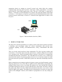
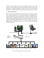
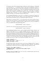
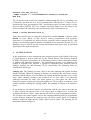
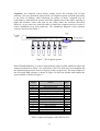
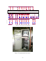
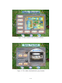
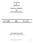
A SCHEME FOR AN AUTOMATED MODERN HOME
Assoc. Prof. Dr. Muhammed Abdelati1
ABSTRACT: Most people who plan to build a home have a good idea about what types of amenities
their new place should have. Preferences reflect both the unique tastes and the special needs of each
homeowner. However, the pace of technological development has stayed far ahead of their ability to
assimilate the innovations. For example, it is possible now for the public users to be in contact with their
homes any time they want. They can check what is going around, switch off lights and open water pumps.
However, hardware and software to control home automation systems are complex and expensive. It is
the aim of this work to create a low cost system for home automation with a user-friendly graphical
interface. The scheme utilizes a commercial programmable logic controller (PLC) from DELTA
manufacturer interfaced to a personal computer to provide a Human Machine Interface (HMI). An
ActiveX control tool is implemented to simplify communication between personal computers and
DELTA PLC which use MODEBUS protocol. Such tool is unavailable in the literature and it is expected
that this tool make significant development in many PLC-based systems especially at Gaza where
DELTA PLCs are increasingly utilized. The proposed framework which is not limited for home
automation is implemented and tested successfully in a project of garden automation for the Islamic
University of Gaza where automatic irrigation, lighting, and fountains control functions are encountered.
KEYWORDS: Automation, smart house, PLC, HMI, automatic irrigation, ActiveX.
1.
INTRODUCTION
Rapidly evolving technology is creating a quit revolution in controls. Understanding
this technology can help professionals and customers utilize its potential for expanding
the horizons of independent living. The automation of many environmental control
tasks will affect every housing consumer [1,2]. It is a unique area of product
development that both enables and demands the application of universal design
principles. Automation with Programmable Logic Controllers (PLCs) has opened up a
fascinating and virtually limitless control word [3,4,5,6,7]. A PLC is a special purpose
computer that reads input signals, runs control logic, and then writes output signals.
While commercial PLCs are relatively cheap, they have a weak point which is the fact
that they are not the best at reading and writing databases, generating reports and
displaying data and information to the operator. Therefore they are rarely used in home
automation. Instead, manufacturers develop special expensive control equipment.
However, PLCs may be interfaced to personal computers, and the limitations mentioned
above are resolved by utilizing the power of PCs. A computer system or other electrical
device which provides an interface to a machine for a human is called Human Machine
Interface (HMI) as illustrated in Figure 1. Sometimes it is referred to as MMI; Man
Machine Interface [8]. In this work we propose a low cost and viable scheme for home
1
The author is with the department of Electrical and Computer Engineering at the Islamic University of
Gaza.
U-1
automation based on creating an ActiveX control tool which hides the complex
communication between PLCs and PCs and hence enable programmers to develop
professional PC based HMI applications easily. The rest of this paper is organized as
follows: In Section 2, home automation is reviewed. The proposed scheme is described
in Section 3. In Section 4 we describe a practical project implementation based on the
proposed scheme and finally in Section 5, comments and suggestions for future work
are given.
HMI
PLC
Figure 1. Human Machine Interface (HMI).
2.
HOME AUTOMATION
The basic idea of home automation is to employ sensors and control systems to monitor
a dwelling, and accordingly adjust the various mechanisms that provide heat,
ventilation, lighting, security, telecommunications, safety, entertainment and other
services.
There are clearly many benefits to home automation. The first is greater comfort and
convenience. A second is improved safety and security. A third is a high level of control
over operating costs. Home automation allows systems in the home to communicate
automatically and share information. The individual does not have to be continuously
involved in the control of system operations; moreover, he or she does not have to make
decisions about the operation of individual systems nor about the relationships between
them.
Home automation can encompass garden irrigation systems, pool and fountains control.
Watering patterns for trees, ferns and rose gardens can be individually programmed. By
adding a photo-electric cell we can allow the garden to be only watered after darkness
(maximum absorption) and one can also add moisture sensors that will allow watering
the garden only when it needs it. With home automation also there is no need to worry
about the lights in the garden. The lights may be programmed to switch on at sunset and
switch off at midnight. Likewise, the fountain is programmed to run only during the
day.
U-2
Commercial home automation systems are unfortunately expensive and usually
packaged as fully integrated systems. Standard integrated packages usually include
security systems, lighting and appliance control. Interface panels and remote access
capabilities are essential components of integrated systems and some individual
subsystems as well. Both wireless and hard-wired systems are available [9,10,11,12,13].
3.
PROPOSED SCHEME
Figure 2 shows the block diagram of the system architecture, where there are a master
PLC and a server computer. The PLC is connected to the server through the RS-232C
serial communication interface. The system logic functions are implemented by a
Sequential Function Chart (SFC) realized by the PLC while the user interface is done by
means of software designed and loaded in the server computer [14]. The software is
implemented using Visual Basic and based on utilizing the especially created ActiveX
control tool which enables communication between the PC and the PLC in a very user
friendly manner. Connecting the server to a network enables monitoring and
administrating the PLC using remote clients. The ActiveX control has the functions
summarized in Table 1.
Server
Client
LAN
RS232, MODBUS Protocol
Handle
Programming
Panel
Entertainment
DELTA PLC
Lighting
Security
Air Condition
Appliances
Communication
Figure 2. Block diagram of the system architecture.
U-3
Garden
Function Name
ReadInputX
ForceCoilS
ForceCoilY
ForceCoilM
ForceCoilT
ForceCoilC
ReadCoilS
ReadCoilY
ReadCoilM
ReadCoilT
ReadCoilC
PresetRegisterT
PresetRegisterC
PresetRegisterD
ReadRegisterT
ReadRegisterC
ReadRegisterD
Action
Read State
Set/Reset
Set/Reset
Set/Reset
Set/Reset
Set/Reset
Read State
Read State
Read State
Read State
Read State
Set Value( 16 bit )
(Hex)
Set Value( 16 bit )
(Hex)
Set Value( 16 bit )
(Hex)
Read Value( 16 bit )
(Hex)
Read Value( 16 bit )
(Hex)
Read Value( 16 bit )
(Hex)
Device
X
S
Y
M
T
C
S
Y
M
T
C
Effective Range
0~127
0~127
0~127
0~1279
0~127
0~127
0~127
0~127
0~1279
0~127
0~127
On Error Return
-1
False
False
False
False
False
-1
-1
-1
-1
-1
T
0~127
False
C
0~127
False
D
0~599
1000~1143
False
T
0~127
-1
C
0~127
-1
D
0~599
1000~1143
-1
Table1. Functions of our ActiveX control tool.
Similar ActiveX controls are available in the literature [15]. However they are not free
and dedicated for other expensive PLC such as OMRON and Modicon.
Like other PLCs, DELTA PLCs have RS232C serial communication interface adapters.
They use the ASCII mode DELTA MODBUS protocol to communicate with PCs
through this interface [16]. This protocol defines a message structure that controllers
will recognize and use, regardless of the type of networks over which they
communicate. It describes the process a controller uses to request access to another
device, how it will respond to requests from the other devices, and how errors will be
detected and reported. It establishes a common format for the layout and contents of
message fields. Messages start with a colon ( : ) character (ASCII 3A hex), and end with
a carriage return-line feed (CRLF) pair (ASCII 0D and 0A hex).
The allowable characters transmitted for all other fields are hexadecimal 0 ... 9, A ... F.
A PLC monitors the RS232C interface continuously for the colon character. When one
is received, it decodes the next field (the address field) to find out if it is the addressed
device. Intervals of up to one second can elapse between characters within the message.
If a greater interval occurs, the receiving device assumes an error has occurred. A
typical message frame is shown in Figure 3.
start
address
function
data
LRC check
end
1 char
2 chars
2 chars
n chars
2 chars
2 chars
CRLF
:
Figure 3. The message frame structure in the MODBUS protocol.
U-4
The function code field of a message frame contains two ASCII characters. Valid codes
are in the range of 1 ... 255 decimal. Of these, some codes are applicable to all PLCs,
while some codes apply only to certain types, and others are reserved for future use.
When a message is sent from a PC to a PLC the function code field tells the PLC what
kind of action to perform. Examples are to read the ON / OFF states of a group of
discrete coils or inputs; to read the data contents of a group of registers; to read the
diagnostic status of the PLC; to write to designated coils or registers; or to allow
loading, recording, or verifying the program within the PLC.
The Longitudinal Redundancy Check (LRC) is calculated by summing up, module 256,
the values of the bytes from the address to last data character then calculating the
hexadecimal representation of the 2's-complement negation of the sum.
When the PLC responds to the PC, it uses the function code field to indicate either a
normal (error-free) response or that some kind of error occurred (called an exception
response). For example, a message from PC to DELTA PLC to force coil number 0
(Y0) on, would have the following message frame:
":00050500FF00F7"+char(13)+char(10)
If the PLC device takes the requested action without error, it returns:
":00050500FF00F7"+char(13)+char(10)
Any programming language may be used to design the HMI software. However, we
adopted Visual Basic as it is a popular language that has a simple syntax [17].
Moreover, it provides an efficient support for accessing databases and it comes with a
powerful development environment with several user-friendly debugging facilities. In
Visual Basic, the MSComm control provides serial communications for applications by
allowing the transmission and reception of data through a serial port [18,19]. Selecting
"Comm1" to be the name of this control, the following code may be used to open and
initialize the serial port COM1 to be compatible with DELTA PLC series:
Comm1.CommPort = 1
Comm1.Settings = "9600, e, 7, 1"
Comm1.PortOpen = True
The MSComm control's OnComm event is used to trap and handle the PLC response.
To display the response message on a TextBox tool named "Response" the threshold
property of the Comm1 tool is set to one and the following code may be used:
Private Sub Comm1_OnComm ()
Response.Text = Response.Text+Comm1.Input
End Function
In order to force coil number 0 on, one may add a command button and write the
following code under its click event:
U-5
Private Sub Set_Click()
Comm1.Output = ":00050500FF00F7"+Chr$(13)+Chr$(10)
End Sub
The created ActiveX control tool simplifies administrating the PLC by providing a set
of functions that hide the low level communication with the PLC. It takes care of
initializing the port, generating the LRC, and checking errors. In other words, it is the
driver to talk to DELTA PLC. For example, selecting "Delta" to be the name of our
ActiveX control, the following code may be used to force coil number 0 on:
Check = Delta.ForceCoilY(0,1)
where the returned value is assigned to the Boolean variable Check. It has the value
False on error. Based on this ActiveX control, programmers with moderate
experience in Visual Basic are able to develop a specific code to manage the PLC and
design a user-friendly graphical interface depending on the controlled system [20, 21].
Databases may be used to log the system and sophisticated reports may be produced
depending on the application needs.
4.
AN APPLICATION
In this application we have implemented the proposed scheme at the Islamic University
of Gaza through a project sponsored by the United Nations Development Program
(UNDP). The project concentrates on an interesting section of home automation related
to gardens and automatic irrigation. The implemented system is not limited to the
control of irrigation only, but also is capable of controlling other functions such as
lighting, jumping jets and fountains [22,23]. Specifically, the following items are
considered in the design:
Jumping jets: The jumping jet water effect is the most stunning and popular fountain
display available. Wherever jumping jet displays are installed, they are always a major
attraction and the subject of conversation. Its cutting mechanism provides a very clean
water jump, enabling designers and architects to use this effect over pedestrian
walkways and other dry areas. The water appears as a clear glass rod, and can be
chopped to appear as glass rods flying through the air. The jets shoot, in sequence, from
planter to planter, looking like leaping snakes. The jumping jet display is an attentiongetter.
In our design we use infrared sensors, as pedestrians walk by, the sensors cause the jets
to play a special fast pattern effect. If no sensor input is triggered in 5 seconds, the
controller switches to "static" mode and runs all effects in a pre-programmed sequence.
The jets have two control signals; one for the cutting mechanism which is programmed
to give different sequences for jumping water, the other control signal is for lighting
which is enabled at night only by using a photo-electric sensor. The jumping jets are
installed as shown in Figure 4.
U-6
Suction
strainer
Figure 4. Jumping jet installation.
Fountains: In our application we implemented two types of fountains: a spray fountain
and a laminar jets fountain which are illustrated in Figures 5 and 6 respectively. Each
one has two control signals one for the water bump and the other is for the fountain
lighting.
Submergible pump
Lights
To control
circuit
Figure 5. Spray fountain
Leakage water
substitution
Figure 6. Laminar jet fountain.
U-7
Irrigation: An irrigation system means ending forever the tiresome job of lawn
watering. Like any permanent improvement, an irrigation system will add appreciably
to the value of gardens, while enhancing the beauty of lawns. Irrigation may be
controlled by using different sensors such that lighting sensor that allow watering at
night and moisture sensor that turn on the pump when the moisture decreased.
However, in our project we used time table to control the irrigation process in order to
reduce installation costs and complexity. The installation diagram of the irrigation
system is shown in the Figure 7.
Figure 7. The irrigation system.
Delta DVP60ES00R PLC is used to implement the control system which has inputs and
outputs summarized in Table 2 for convenience [24]. The electrical circuit diagram and
the implemented board are shown in Figures 8 and 9 respectively. The main window of
the developed HMI software is shown in Figure 10 while the window that handles the
spray fountain is shown in Figure 11.
Signal
Device
Type
Y0
Y1
Y2
Y3
Y4-Y9
Y10-Y11
Y12-Y13
Y14-Y15
Y16
X0
X1
X2
X3-X8
X9
X10
Spray fountain pump
Spray fountain lights
Laminar jet fountain pump
Laminar jet fountain lights
Irrigation channels
Jumping jets cutting mechanisms
Jumping jets lights
Jumping jets pumps
Standby lamp
Spray fountain pump feedback
Spray fountain lights feedback
Photo-cell sensor
Irrigation channels
Infra red sensor
System enable switch
output
output
output
output
output
output
output
output
output
Input
Input
Input
Input
Input
Input
Table 2. Inputs and outputs of the DELTA PLC.
U-8
2
2
2
2
SW7
SW8
1
1
1
R6
1
2
R5
R4
1
1
R3
1
R2
1
1
2
2
R1
photocell
1
C2
1
C1
2
2
2
2
24V DC
0V DC
Control Circuit
S/S
X0
X1
X2
X3
X5
X4
X7
X6
X9
X8
X10
Programmable Logic Controller
C0
Y0
Y1
Y4
Y3
Y2
Y6
Y5
Y7
Y8
Y9
Y11
Y10
Y13
Y12
Y14
Y15
Y16
1
1
1
1
1
1
1
1
SW1
SW2
SW3
SW4
SW5
4
3
2
4
3
2
4
3
2
4
3
2
4
3
2
SR2
4
S2
3
SR1
2
S1
2
2
2
2
24V DC
SW6
2
2
1
M4
2
1
1
M3
2
1
1
C4
M2
V1
lamp
V2
V3
V4
V5
V6
0V AC
0V AC
Figure 8. The electrical circuit diagram.
Figure 9. The implemented electric board.
U-9
1
R12
2
2
2
2
2
2
2
2
C3
R6
1
R5
1
R4
1
1
2
2
2
2
2
1
1
R3
2
2
R2
2
lamp
2
M1
R1
1
1
1
2
2
220V AC
1
11
C4
1
1
C3
2
2
2
2
11
C2
R11
R6
24V AC
C1
R10
1
1
1
R5
R9
1
1
1
R4
1
1
1
R3
2
2
2
2
2
2
220V AC
Power Circuit
R2
1
1
1
C2
R1
0V AC
1
1
1
1
C1
R8
2
C2
2
SR2
2
C1
0V DC
2
SR1
1
LAMP
R7
Figure 10. Main window of the developed software.
Figure 11. The window that handles the spray fountain.
U-10
5.
COMMENTS AND SUGGESTIONS FOR FUTURE WORK
In this work we proposed a framework for a low cost and viable home automation
system. It is based on creating an ActiveX control tool for DELTA PLCs that simplifies
developing HMI applications. Both software and hardware parts are realized and tested
successfully at the Islamic University of Gaza where it is used to manage irrigation,
fountains, and garden lights.
It is expected that this tool make significant development in many PLC-based systems
at least at Gaza where DELTA PLCs are increasingly utilized. The novelty of our work
is its simplicity. One does not need to purchase extremely expensive HMI equipment or
software. Having basic knowledge of PLCs and programming languages, interested
engineers may use the ideas presented in this paper to develop a reliable HMI not only
for home automation, but also for controlling systems of many industries such as
asphalt, fodder, and concrete whose HMI costs dozens of thousands of dollars.
In a future work we plan to develop controllers for distributed control systems where
there are many plants each of which is influenced by certain parameters of other plants
while having a dedicated controller. Usually these distributed systems are networked
and a centralized sophisticated HMI is accompanied to them [25]. Typical examples of
these systems are the electric power generation and water quality control systems [26].
Acknowledgment: The author gratefully acknowledges his students Maha Harara,
Maha Salama, Fadia Abusafia, Amira Aloustath, Soha Alwali, and Rana Elamasi for
their help in this project. Also he is grateful to UNDP team, especially Mr. Mohammed
Elaroky, for allocating and managing the financial support of this research.
6.
REFERENCES
[1]
[2]
[3]
[4]
[5]
[6]
[7]
[8]
[9]
[10]
[11]
[12]
[13]
Hugh Jack, "Automation Manufacturing Systems with PLCs", 2001
Moraes F., Amory A., Calazans N., Bezerra E., and Petrini J., "Using the
CAN Protocol and Reconfigurable Computing Technology for WebBased Smart House Automation", 2001.
http://www.inf.pucrs.br/~moraes/papers/2001_sbcci_can.pdf
http://www.plcs.net/contents.shtml
http://www.htservices.com/Tutorials/plctutorial1.htm
http://a-t-inc.com/Tutorials/plctutorial1.htm
http://www.phoenixcon.com/products/interbus/overview/examples.asp
Gary Dunning, "Introduction to Programmable Logic Controllers",
Delmar, 2002.
http://www.styrex.se/kunskapsbanken/STYREX_HTML/Tutorial/Mmi.html
http://www.smarthome.com
http://www.homeauto.com
http://www.homecontrols.com/index.html?id_hci=0316HC694362
http://www.csi3.com/homevis2.htm
http://www.sbt.net.au/links/x-10.html
U-11
[14] Muhammed Abdelati," Syntheses of a Discrete Events System", the Second
Conference of the Islamic University on Mathematical Sciences, IUG, Gaza, 2728 August 2002.
[15] www.industrialvb.com
[16] http://www.modbus.org
[17] Gene Swartzfager, Ramesh Chandak, and Purshottam Chandak, " Visual Basic 6
Object-Oriented Programming Gold Book", 1998.
[18] http://www.yes-tele.com/mscomm.html
[19] http://www.ontrak.net/visual.htm
[20] Jeff Weigant,"Creating Human Machine Interfaces Using Visual Basic", 4th ed,
IndustrialVB, 2000.
[21] Thomas E. Leonik, "Home Automation Basics", PROMPT Sams, 2000.
[22] http://pemfountain.ca/home.html/515.pdf
[23] http://www.atlanticfountains.com/leapfrog.htm
[24] DELTA Electronics, Inc., "DVP-PLC user manual", 2001.
[25] http://www.matrikon.com
[26] M. Polycarpou, J. Uber, Z Wang, F. Shang, and M. Brdys, "Feedback Control of
Water Quality", IEEE Control Systems Magazine, June 2002.
U-12