1
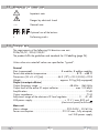
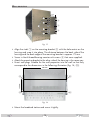
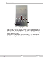
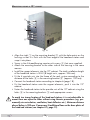
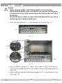
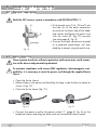
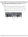
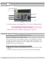
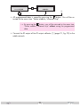
Head-End Station
English
STC 160
GSS
Grundig SAT Systems GmbH
Beuthener Strasse 43
D-90471 Nuremberg
Phone:
Fax:
Email:
Internet:
+49 (0) 911 / 703 8877
+49 (0) 911 / 703 9210
[email protected]
www.gss.de/en
Contents
1 Notes about safety and hazards......................................................................... 3
2 General information........................................................................................... 4
2.1 Scope of delivery................................................................................ 4
2.2 Available accessories........................................................................... 4
2.3 Meaning of the symbols used................................................................ 5
2.4 Technical data.................................................................................... 5
2.5 Description......................................................................................... 6
3 Overview........................................................................................................... 7
3.1 Front cover......................................................................................... 7
3.2 Front view (without front cover)............................................................. 7
3.3 Rear view........................................................................................... 8
3.4 Control panel...................................................................................... 9
4 Assembly......................................................................................................... 10
4.1 Remove front cover............................................................................ 10
4.2 Remove base plate............................................................................ 10
4.3 Making an earth connection............................................................... 11
4.4 Installing F terminals.......................................................................... 12
4.5 Installing an additional fan................................................................. 12
4.6 Mounting......................................................................................... 13
Wall mounting............................................................................. 14
Upright mounting......................................................................... 15
Mounting inside a 19" cabinet...................................................... 16
5 Installing modules............................................................................................. 17
6 Connecting the head-end station....................................................................... 18
6.1 Potential equalisation......................................................................... 18
6.2 Mains connection.............................................................................. 18
6.3 RF connections.................................................................................. 19
7 Settings............................................................................................................ 20
7.1 Contrast of the display....................................................................... 20
7.2 Settings in the menu........................................................................... 20
Setting the output level of the RF output collector.............................. 20
Setting the standard of the output signal.......................................... 20
8 Final procedures............................................................................................... 23
- 2 -
STC 160
1
N otes
a bo u t sa fe t y a n d h a z a r ds
• The head-end station is subject to the regulations of protection class I.
• Never operate the device without a protective earth connection, earth connection to the device and potential equalisation!
• The standards EN/DIN EN 50083 resp. IEC/EN/DIN EN 60728 must be
observed.
• Observe the relevant country-specific standards, regulations and guidelines
on the installation and operation of antenna systems.
• Replace mains cable and power supply unit only by original spare parts.
• Do not perform installation and service work during thunderstorms.
• Assembly, installation and servicing must be carried out by an authorised
electrician.
• Switch off the operating voltage of the system before beginning with assembly or service work or pull out mains plug.
• The device should only be installed in a room where the permissible ambient temperature range of 0°C…+50°C can be maintained, even during
fluctuations in climatic conditions.
• To avoid too strong heating of the head-end station it is not admissible to
mount them one upon the other without using thermic precautions (e.g.
permanently air recirculation, ventilation, heat deflectors etc.).
• Do not install the device in cabinets or recesses which are not ventilated.
• If additional fans are to be used to circulate the air, ensure that the system
will be shut down (disconnected from mains) should any one of the fans fail.
• In case of the formation of condensation wait until the system is completely dried.
• Do not cover the ventilation openings!
• During installation, observe a minimum distance of
- 500 mm above/below and 75 mm behind the device at wall mounting,
- 500 mm above and 75 mm below/behind the device at upright mounting,
- 200 mm above/below and 100 mm behind the device at mounting in a
19" cabinet.
• Install the system …
- on a vibration-free wall or floor construction
- In a dry, dust-free environment
- In such a manner that it is protected from moisture, fumes, splashing water and dampness
- Where it is protected from direct exposure to sunlight
- Not within the immediate vicinity of heat sources
• Do not place any vessels containing liquids on the device.
• Do not place anything on the head-end station which could initiate fires
(e.g. candles).
- 3 -
STC 160
• Due to the risk of fires caused by lightning strikes, we recommend that all mechanical parts (e.g. distributor, equipotential bonding rail, etc.) be mounted
on a non-combustible base. Wood panelling, wooden beams, plastic covered panels and plastic panels are all examples of combustible bases.
• Avoid short circuits!
• To ensure electromagnetic compatibility, make sure all connections are tight
and that the covers are screwed on securely.
• No liability is accepted for damage caused by faulty connections or inappropriate handling of the device.
• You can obtain additional information from the "Planning handbook" brochure which can be found on the website "www.gss.de/en" under the
"Service" category.
Take precautions to prevent static discharge when working on the device
and the modules!
Electronic devices should never be disposed of in the household rubbish. In
accordance with directive 2002/96/EC of the European Parliament and the
European Council from January 27, 2003 which addresses old electronic and
electrical devices, such devices must be disposed of at a designated collection
facility. At the end of its service life, please take your device to one of these
public collection facilities for proper disposal.
2
General
2.1 S c o p e
i n fo r m ati o n
o f d e l i v e ry
1 STC 160 head-end station (without modules)
1 Power cord
1 Ferrite sleeve
1 DVD (assembly instructions)
1 Brief assembly instructions
1 RF connection cable with/and terminal,
(RF output when retrofitting a RF output collector)
1 Ribbon cable (for retrofitting a RF output collector)
Mounting material
2.2 A va i l a b l e
acc e s s o r i es
Modules and accessories see website "www.gss.de/en".
- 4 -
STC 160
2.3 M e a n i n g
o f t h e s ym b o l s u s e d
Important note
Danger by electrical shock
—>
–
–
/
/
General note
Optional use of the buttons
•Performing works
2.4 T e c h n i c a l
data
The requirements of the following EU directives are met:
2006/95/EC, 2004/108/EC
The product fulfils the guidelines and standards for CE labelling (page 24).
Unless otherwise noted all values are specified as "typical".
General
Slots (unoccupied): .......................................8 modules, 8 add-on modules
Permissible ambient temperature:..........................................0 °C … +50 °C
Dimensions (W x H x D) [cm]: ...................44.3 (19") x 35.5 (8 HU) x 22.8
Weight:...................................................... approx. 20 kg (fully equipped)
Output (via output collector)
Output frequency range:............................................48 MHz ... 865 MHz
Output level of the active RF output collector:....................... max. 100 dBμV
Amplification:.................................................................................19 dB
Output impedance:.......................................................................... 75 Ω
Adjustment range of the electronic RF level regulator:................. 0 … –31 dB
LNB power supply:............................................+ 12 V / max. 800 mA
(short-circuit proof/multi-fused)
Mains unit
Mains voltage:..................................................... 220–240V~, 50/60 Hz
Power consumption: . .....................................210 W max.; fully occupied,
incl. LNB power supply
- 5 -
STC 160
2.5 D e s c r i p t i o n
Proper installation of the mounting bracket enables the STC 160 head-end station to be installed in a 19" cabinet as well as on a wall or upright standing.
The head-end station is modular in design and can be equipped with 8 standard plug-in modules and 8 add-on modules. A current list of the standard and
add-on modules can be found on the website "www.gss.de/en". This headend station is designed exclusively for use with these modules.
The various expansion options for the head-end station allow for the installation of a wide range of broadband cable systems.
Input SAT IF distributors and an output collector can be upgraded to offer the
highest degree of flexibility for the distribution of the signals.
The power supply in the STC 160 head-end station is designed to supply
power to components (e.g. LNB) connected upstream.
All RF output signals from the modules are combined via the inputs of a retrofitted active RF output collector and prepared for distribution through the RF
output socket.
When the head-end station is shipped from the factory, the default setting for
the control voltage for a RF output collector is maximum. If necessary please
set the master output level to the value required for the respective cable system.
When the head-end station is switched on, the two-line LC display shows the
"SETUP" menu and the software version of the control unit. The head-end station output level can be adjusted in submenu "OUTPUT", the output standard
can be adjusted in submenu "NORM".
The operating software for the control unit and modules can be updated via
the 9-pin SUB-D socket of the head-end station using a PC or notebook and
the software "BE-Flash". Current versions of the software can be found on the
website "www.gss.de/en".
- 6 -
STC 160
3
O v e rv i e w
3.1 F r o n t
c ov e r
2
1
2
1
1
2
1
2
Fig. 1
1 Locking screws (incl. with delivery in a separate package)
2 Fastening screws
3.2 F r o n t
view
(with o ut
f ro n t c ov e r )
2
3
1
4
Fig. 2
1
2
3
4
Knock-outs for upgrading a RF output collector / cable inlets
Knock-outs for the SAT IF input distributors
Control panel
Knock-outs for F terminals
- 7 -
STC 160
3.3 R e a r
view
1 2
3
4
5
6
5
7
Fig. 4
1 Power cord socket
2 Main power switch
3 Earth connection terminal
4 RF output
5 SAT IF inputs
6 Knock-outs for additional F terminals
7 Knock-out for the optional installation of the earth connection terminal
- 8 -
STC 160
3.4 C o n t r o l
pa n e l
1
2
3
4
5
6
4
M
S
8
9
5
Fig. 5
1
2
3
4
5
6
7
8
9
LC display
Button to adjust the contrast of the display
Mode indicator
– To adjust values and functions
– Moves the cursor, adjusts functions
– Stores the programmed data
– To adjust values and functions
– To switch to the next menu
9-pin SUB-D socket for updating the operating software of the modules
and the head-end station
0
– Moves the cursor, adjusts functions
- 9 -
STC 160
4
A ss em b ly
4.1 R e m ov e
f r o n t c ov e r
2
1
2
1
1
2
1
2
Fig. 6
• Loosen 4 fastening screws 2.
• Remove 6 locking screws 1 (not required for initial assembly).
• Slide the front cover upwards and remove it from the head-end station.
4.2 R e m ov e
ba s e p l at e
2
2
2
1
Fig. 7
• Remove the locking screw 1.
• Remove the fastening screws 2.
• If applicable, unscrew the nuts of retrofitted F terminals (not required for
initial assembly).
• Push the base plate in direction of the arrow and remove it.
- 10 -
STC 160
4.3 M a k i n g
an earth connection
The pre-installed earth connection terminal in position
position 2 (fig. 8).
1
1 can be relocated to
2
Fig. 8
• Dismount the earth connection terminal so that it can be moved.
• Mount the earth connection terminal (according to fig. 9) in position
shown in fig. 8.
2 as
Housing
Fig. 9
Caution
Tighten the nut until the teeth on the lock washer have penetrated the exterior
coating and a good connection is made between the housing and earth connection terminal.
- 11 -
STC 160
4.4 I n s ta l l i n g F t e r m i n a l s
Fig. 10
• Insert the required number of standard F terminals in the openings provided (knock-outs) in the front (page 7, fig. 2, 4) and/or rear panel (page
8, fig. 4, 6).
Caution
Tighten the nuts until the teeth on the lock washers have penetrated the exterior
coating and a good connection is made between the housing and F terminals.
4.5 I n s ta l l i n g
a n a d d i t i o n a l fa n
If environmental conditions require the use of an additional fan, one can be
screwed to the inside of the base plate (hole spacing: 82 x 82 mm).
82 mm
82 mm
Fig. 11
• Remove base plate (page 10).
• Mount the fan (12 V / 1 A
max.) in position 1 or
inside of the base plate with screws.
• Make the electrical connection as shown in fig. 12.
- 12 -
2 (fig. 11) to the
STC 160
–
+ 12 V / 1 A
Fig. 12: Power supply for additional fan
4.6 M o u n t i n g
– Install the head-end station vibration-free.
Avoid, for example, mounting the head-end station onto a lift shaft or any
other wall or floor construction that vibrates in a similar way.
– To avoid too strong heating of the head-end stations it is not admissible
to mount them one upon the other without using thermic precautions (e.g.
permanently air recirculation, ventilation, heat deflectors etc.).
– Using the supplied mounting brackets, the head-end station can be mounted
to a wall, upright standing, or in a 19" cabinet. Before proceeding, ensure
that the minimum distance requirements (500 mm above/below and 75
mm behind the device at wall mounting / 500 mm above and 75 mm below/behind the device at upright mounting / 200 mm above/below and
100 mm behind the device at mounting in a 19" cabinet) will be met.
– If mounting to a wall or on a shelf, ensure that ...
- The wall or the shelf can support the weight of the head-end station
- There is adequate air conditioning
- The permissible ambient temperature will be maintained
– If mounting inside a 19" cabinet, ensure that ...
- there is adequate air conditioning.
- the permissible ambient temperature will be maintained.
- the mounting rack in the cabinet can support the weight of the head-end
station.
Note:
To maintain an ambient temperature of < 50 °C, use an additional fan or a
safety temperature limiter with reclosing interlock if necessary.
- 13 -
STC 160
Wa l l
mounting
75 mm
1
4
1
2
3
1
4
1
Fig. 13
• Align the studs 1 on the mounting bracket 3 with the hole matrix on the
housing and snap it into place. The distance between the back side of the
housing and the back edge of the mounting bracket is approx. 75 mm.
• Screw in the 6 thread-forming countersunk screws 2 that were supplied.
• Attach the mounting bracket to the other side of the housing in the same way.
• IInsert wall plugs suitable for the wall properties into the wall so that they
correspond to the dimensions in the following illustration (fig. 14, !).
465 mm
!
140 mm
!
!
!
Fig. 14
• Mount the head-end station and screw it tightly.
- 14 -
STC 160
Upright
mounting
2
1
1
1
1
75 mm
3
Fig. 15
• Align the studs 1 on the mounting bracket 3 with the hole matrix on the
head-end station housing and snap it into place. The distance between
the underside of the head-end station and the lower edge of the mounting
bracket is approx. 75 mm.
• Screw in the 6 thread-forming countersunk screws 2 that were supplied.
• Attach the mounting bracket to the other side of the housing in the same
manner.
- 15 -
STC 160
Mounting
inside a
19"
cabinet
5
1
2
1
3
5
1
2
1
Fig. 16
• Align the studs 1 on the mounting bracket 3 with the hole matrix on the
housing so that it is flush with the front edge of the head-end station and
snap it into place.
• Screw in the 4 thread-forming countersunk screws 2 that were supplied.
• Attach the mounting bracket to the other side of the housing in the same
manner.
• Install the support elements into the 19" cabinet. The total installation height
of the head-end station is 8 HU (8 height units, approx. 356 mm).
• Fit the 4 prestole nuts into the frame of the rack system according to the
distance of the holes 5 in the mounting bracket 3 (approx. 190 mm).
• Connect the head-end station according to chapter 6 (page 18) .
• Put the head-end station onto the support elements, push it into the 19"
cabinet.
• Fasten the head-end station to the prestole nuts of the 19" cabinet using the
holes 5 in the mounting brackets 3 and appropriate screws.
To avoid too strong heating of the head-end stations it is not admissible to
mount them one upon the other without using thermic precautions (e.g. permanently air recirculation, ventilation, heat deflectors etc.). Minimum distance
above/below is 200 mm. If necessary fit additional fans on the base plates of
the head-end stations (see chapter 4.5, page 12).
- 16 -
STC 160
5
I ns ta l l i n g
m o d u l es
Caution
– Always position modules which belong together next to each other.
– When installing modules, make sure that they are inserted in the long numbered grooves in front of the contact strip on the board at the rear wall of
the housing.
The shorter grooves without a contact strip on the board at the rear wall of
the housing are for add-on modules only.
• Open the locking device
1 in the direction of the arrow (fig. 17).
1
Fig. 17
2
1
3
Fig. 18
• Insert a module in grooves 1 and 2 of an open slot (fig. 18) and gently
slide it into the head-end station until it makes contact with the board on the
rear wall.
• After installing a module close the locking device 3 in the direction of the
arrow (fig. 18).
- 17 -
STC 160
6
Connecting
6.1 P ot e n t i a l
t h e h e a d - e n d s tati o n
e q ua l i sat i o n
Earth the SAT receiver system in accordance with DIN EN 60728-11.
A
B
Housing
Fig. 19
6.2 M a i n s
•Put the earth wire (Cu 4 - 20 mm2) into
the hole A of the earth connection
terminal on the back side of the headend station and fasten the earth wire
with the screw B (fig. 19) securely
(see also page 8, fig. 4).
• Connect the earth connection terminal
to a potential equalisation rail (supplied by customer) using the earth wire.
connection
Never operate the device without a protective earth connection, earth connection to the device and potential equalisation!
To maintain compliance with current EMC regulations (electromagnetic compatibility), it is necessary to route the power cord through the supplied ferrite
sleeve.
• Open the ferrite sleeve.
• Make a loop in the power cord and lay the loop inside the ferrite sleeve as
shown in fig. 20.
• Close the ferrite sleeve (fig. 21).
Fig. 20
Fig. 21
• Connect the power cord to the power socket 1 (page 8, fig. 4) on the
head-end station and plug the other end into an earthed mains socket.
- 18 -
STC 160
6.3 RF c o n n e c t i o n s
To comply with the current EMC regulations, it is necessary to connect the lines
leading in and out of the head-end station using F terminals.
Note:
The F terminal at the rear panel are intended to use for RF input and RF output.
The following connection example shows a possible connection scheme.
• Connect the RF output of the head-end station (fig. 22, 4) to the cable
network.
• Connect the SAT IF cables coming from the LNBs to the relevant F terminals
(fig. 23, 5).
1 2
3
4
5
6
5
7
Fig. 22
- 19 -
STC 160
7
S e t ti n gs
7.1
Contr ast
o f t h e d i s p l ay
1
2
8
M
3
4
5
6
4
S
9
5
Fig. 24
• Using the main power switch, (page 8, fig. 4, 2) switch on the head-end station.
—> The mode indicator
• Adjust the contrast of the display using the button
7.2
S e t t i n gs
Setting
t h e o u t p u t l e v e l o f t h e RF o u t p u t c o l l e c to r
Setting
t h e s ta n da r d o f t h e o u t p u t s i g n a l
After the output levels of the modulator modules or the modulators have been
set, check the master output level of the RF output collector and adjust it accordingly based on the requirements of the cable system. Afterwards set the
standard of the output signal required.
Setting the output level of a retrofitted RF output collector
• Connect the RF outputs of the modulators to the RF inputs of the RF output
collector.
• Connect the antenna test receiver to the output of the RF output collector.
3 (fig. 24) is activated.
2 (fig. 24).
in the menu
- 20 -
STC 160
• After switching on the head-end station the "Select module / channel strip"
– "SETUP BE160" menu appears in the display. Activate this menu by repeatedly pressing
if needed.
SETUP
Ein/On
Bx 1A
TWIN-SAT
Böx 4
TWIN-SAT
Bx 1A
DVBT
C5-12,S3-24
C07
C5-12,S3-24
C07
C 69
BE160
V 10
M
• Press the
button.
—> The "Set output level" – "OUTPUT Level" menu is activated.
SETUP
Level
• Using the
system.
• Press the
OUTPUT
0
buttons, set the RF output level as required for the cable
button.
—> The "Standard of the output signal" – "NORM" menu is activated.
Standard of the output signal
SETUP
NORM
PAL BG
• Using the
system.
buttons, set the output standard as required for the cable
—> Here e.g. you can set the head-end station to PAL D/K standard for
using OIRT modeles. Always all modulator modules are set. Mixed
operation is not possible!
—> The used modulator modules must support the selected standard.
• Press the
button.
—> The "Store data" – "MEMORY" menu is activated.
- 21 -
STC 160
SETUP
MEMORY
S => STORE
M
CANCEL
A
S
• All programmed data is saved by pressing the
button. You will be returned to the menu item "Select module / channel strip".
—> By pressing the
button, you will be returned to the menu item
"Select module / channel strip" without saving the programmed
data.
• Connect the RF output of the RF output collector 1 (page 21, fig. 25) to the
cable network.
- 22 -
STC 160
8
Fi n a l
pro c e d u r es
After installing the head-end station, upgrading accessories or installing modules it is necessary to tighten all cable connections, F terminals and cover
screws in order to maintain compliance with current EMC regulations.
• Securely tighten the cable connections (F connector) using an open-ended
spanner (spanner width 11 mm).
2
2
1
2
Fig. 26
• Position the breakthroughs in the base plate above the fastening screws 2
(fig. 26).
• Push the base plate in direction of the arrow and lock it with the locking
screw 1 (fig. 26).
• Tighten the fastening screws 2.
• Tighten the nuts of retrofitted F terminals if applicable.
• Hang the front cover on the fastening screws 2 (page 10, fig. 6).
• Secure the front cover using the 4 locking screws 1 (page 10, fig. 6)
which were supplied for the initial installation.
• Tighten the fastening screws 2 (page 10, fig. 6).
2
1
2
1
1
2
1
2
Abb. 27
- 23 -
STC 160
Service:
Phone:
Fax:
E-mail:
+49 (0) 911 / 703 2221
+49 (0) 911 / 703 2326
[email protected]
Alterations reserved. Technical data E. & O.E.
© by GSS GmbH V10/28062013