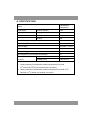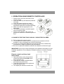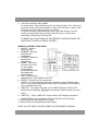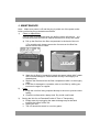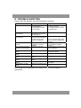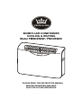
1
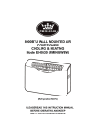
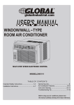
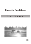
8000BTU AIR CONDTIONER
COOLING & HEATING
Model PMINISW8W / PMINISW8C
PLEASE READ THIS INSTRUCTION MANUAL
BEFORE OPERATING AND KEEP
SAFE FOR FUTURE REFERENCE
CONTENT
Title
Page
A. Specification
3
B. Before use
4
C. Important safety instructions
5, 6
D. BS plug wiring
7
E. Product description
8, 9
F. Wall mounting installation instruction
10-14
G. Assembly instruction for mobile unit (only available
in combi model)
15, 16
H. Operating instructions
17-21
I. Operation using remote controller
22, 23
J. Maintenance
24
K. Trouble shooting
25
L. Service & warranty
26
2
A. SPECIFICATION
PMINISW8W
Model
PMINISW8C
Capacity(W)
Power
Cooling Capacity
2300
Heating Capacity
2400
Cooling
920
Heating
960
Dehumidifying Capacity (L/day)
25
3
Air Volume (m /h)
320
Power Supply
220-240V ~ /50Hz
Noise Level (dB)
49
Refrigerant (g)
R407C / 400g
Net Weight(KG) (not includes accessories)
32
Dimension
Body (mm)
465*765*235
(H*W*D)
Package (mm)
536*930*315
Notes:
1. Cooling capacity is measured at ambient temperature Dry-bulb
27OC,Wet-bulb 19OC(Indoor and outdoor, the same).
2. Heating capacity is measured at ambient temperature Dry-bulb 20 OC,
Wet-bulb 15 OC (Indoor and outdoor, the same).
3
B. BEFORE USE
Transport & store the unit in an upright position only. Leave it in an upright
position for at least 3 hours before first use.
DO NOT dispose of any packaging until the installation of the air
conditioner is completed.
After having removed the packing, check that all the content is intact and
complete. (See list of accessories). In the event of missing parts, contact
your retailer.
This air conditioner has been designed to cool or heat the air of a room
and should only used for the purpose.
The manufacturer cannot be held liable for damage caused to property or
injury to persons or animals due to incorrect installation, regulation and
maintenance or improper use.
This air conditioner contains R407C refrigerant: at the end of its life, the
disposal of this air conditioner must be in accordance with the strict
regulation governing the recycling of this product, please operate with
caution during the disposal. Please contact your local authority for
regulatory advice.
DO NOT switch on before having totally assembled the air conditioner and
before installing in its correct operating position.
4
C. IMPORTANT SAFETY INSTRUCTIONS
Always place the unit on an even, level surface.
An opening in a window (in portable version only) or wall is required to
accommodate the exhaust hose to expel the hot air.
Ensure the unit is connected to an earthed power supply of the correct
rating. (Refer to the rating label located at the back of the unit).
The unit will cool when the room temperature is between 18°C~32°C
depending on the thermostat setting.
DO NOT use this unit for functions other than those described in this
instruction manual.
DO NOT tilt the unit.
DO NOT cover or obstruct the appliance’s inlet and outlet grilles.
Your air conditioner has been designed to be used only in the home, office
and similar conditions and should not be used for any other purpose.
This unit is for indoor use only.
Never unplug the air conditioner while it is working, this could damage the
electronic circuits.
DO NOT use the appliance in a wet room, such as a bathroom or laundry
room to avoid the risk of electrical shocks.
DO NOT bend or crush the warm air exhaust hose. (in portable version
only)
DO NOT sit or place articles on the appliance.
DO NOT use the appliance with wet or damp hands.
DO NOT let chemical substances come into contact with the appliance.
DO NOT use the appliance in the presence of flammable substances or
vapours such as alcohol, insecticides, petrol, etc.
DO NOT use the plug to start and stop the appliance. ALWAYS use the
intended control panel to start and stop the unit.
ALWAYS turn off the appliance when it is not in use and remove the mains
plug from the socket outlet.
ALWAYS turn the unit off and remove the mains plug before cleaning,
carrying out maintenance or moving location.
Do not pull the electrical cable or place it near a source of heat: always
unroll it completely to avoid dangerous overheating. If the power cord
becomes damaged, the service agent or a similarly qualified person must
replace it, in order to avoid a hazard.
The filter must be used with the product at all times, when removing it for
clearing always turn the unit off and unplug the mains plug from the
socket.
Do not operate the unit with a damaged power cord or plug, after it
malfunctions, has been dropped or damaged. If the power cord is
damaged it must be replaced by the manufacturer or a qualified service
engineer to avoid a hazard.
Closely supervise any children and pets when unit is in use
5
Energy Saving Tips
Blocking of the filter reduces the efficiency of the air and increases its
power consumption by up to 6%.
Avoid opening doors frequently.
Each person present in a room provides between 100 Watts and 150
Watts of heat. Consequently, the more people there are in a room, the less
effective the unit will be in cooling.
To ensure the optimal efficiency of the unit, we advise you to keep doors
and windows closed, and to take into account the surface of the walls and
windows exposed to the sun.
Avoid the use of adapter plugs, multiple sockets and /or extension leads. If
their use is necessary, ensure they conform to current safety standards.
Before starting the appliance, check that it is correctly earthed, according
the legislation in force in the country concerned.
READ AND SAVE THESE INSTRUCTIONS
6
D. BS PLUG WIRING
Wiring Instructions: Should it be necessary to change the plug please note the
wires in the mains lead are coloured in accordance with the following code:
BLUE - NEUTRAL
BROWN - LIVE
GREEN AND YELLOW - EARTH
As the colours of the wires in the mains lead of this appliance may not
correspond with the coloured markings identifying the terminals in your plug,
proceed as follows:
1. The BLUE wire is the NEUTRAL and must be connected to the terminal,
which is marked with the letter N or coloured BLACK.
2. The BROWN wire is the LIVE and must be connected to the terminal, which
is marked with the letter L or coloured RED.
3. The GREEN/YELLOW is the EARTH and must be connected to the
terminal which is marked with the letter E or
or coloured GREEN OR
GREEN/YELLOW.
4. Always ensure that the cord grip is positioned and fastened correctly.
If a 13A (BS 1363) fused plug is used it must be fitted with a 13A fuse. If in
doubt consult a qualified electrician.
Wiring for a 13 Amp Plug (BS1363)
Please note. The Earth Terminal is marked with the letter E or Earth Symbol
7
E. PRODUCT DESCRIPTION
1.
Air outlet
8.
2.
VFD display
9.
3.
Remote control storage
10.
4.
5.
6.
7.
Control panel
Handles
Dust filter
Hanging holes (for wall mount
brackets)
11.
12.
13.
14.
Standard accessories
A1. Remote control
A2. Fix head with manual adjust louvre
(Pre-installed)
A3. User manual
A4. Drain hose
A5. Rubber plug
** Batteries not included
8
Wire control connection
(optional)
Caster bracket locking holes
(using in mobile version only)
Caster bracket hanging hole
(using in mobile version only)
Air exhaust
Air inlet
Drainage hole
Caster bracket hanging hole
(using in mobile version only)
Wall mounted kit:
W1. Wall bracket
W2. Pipe flange
W3. Air intake pipe (dia.120mm)
W4. External grating
W5. Hot air discharge pipe (dia.130mm)
W6. Template for wall drilling
W7. Extension condensate hose
W8. Screw kit
Mobile kit (optional):
P1. Castors assembly
P2. Metal grille
P3. Unit flange
P4. Air exhaust hose connector
P5. Air exhaust hose
P6. Adapter for window panel
P7. Adjustable window panel
P8. Butter-fly screw x 2
P9. Screw x 4
P10. Insulated sleeve
Schuko to UK converter plug
This Schuko to UK converter plug is used in this product. Refer to UK
plug wiring instruction section for regular UK plug wiring.
9
F. WALL MOUNTING INSTALLATION INSTRUCTIONS
1. Positioning the air conditioner
To obtain maximum performance
from your unit, it must be
correctly positioned. Please
following the guidelines and
instructions below in full, as
failure to do so could cause
potential installation problems:
The air conditioner must be
installed on an exterior wall that
has access to the outside and a
minimum of 2 meters free
clearance to allow good airflow
The unit must be fitted
following the template, with
space to the top, bottom and
sides of the unit.
The wall on which the unit is
installed must be sturdy and able to withstand the weight of the unit.
After determining the best place for installation as described above,
please check to ensure that the wall can be drilled without causing
damage to the fabric of the building. If necessary obtain professional
advice to ensure that no damage is done to power supply or water pipes.
Please also ensure that there are no obstacles on the outside of the wall
which may interfere with the performance of the unit.
10
MINIMUM DISTANCE FROM CEILING
420mm
COMPULSORY FIXING POINTS
EXTRA FIXING POINTS TO USE IF THE WALL IS NOT SOLID
62
62
62
62
62
36
160
HOT AIR
DISCHAGE
HOLE
AIR INTAKE HOLE
?132
93
93
473.7
171.3
40
?8
726
62
188
?132
Remark: 160MM TWO COMPULSORY
FIXING POINTS FOR INDOOR PIPE
ADAPTORS
160
DRAINAGE HOLE
241
All Dimensions are in MM
Drawing paper size: A1
MINUMUM DISTANCE
FROM FLOOR
500mm
?30
2.6
2. Template
Fasten the template to the wall once the following guidelines have been
thoroughly checked.
Do not drill any holes until you are 100% confident that there are no
obstacles in the area you wish to drill and there are no obstructions, which
could be hidden by the construction of the wall, for example: Electrical
wiring, water &gas pipes or supporting lintels or beams.
Ensure that a spirit level is used, as the unit must be level.
Follow the installation instructions & measurements in full.
11
3. Drilling the Wall
Please note: If you are drilling the hole above ground floor level, please
ensure that the outside area is supervised until drilling has been
completed.
INTAKE AND OUTLET HOLES
This operation should be
carried out using the proper
tools (diamond tip or core bit
drills with high twisting torque
and adjustable rotation speed)
Fasten the template to the wall
taking care to check the
distance from the floor and or
ceiling and keep horizontal by
using a spirit level.
Use a pilot drill to mark the
centre of each core hole to be drilled. Use a core boring head having a
diameter of 135mm to drill the two holes for intake and outlet air
It is recommended that the holes must have a slight downward inclination of
3-5 degrees to prevent any backflow of water from the pipes.
Drainage
The unit produces condensate that has to be extracted to enable the unit to
operate correctly. It is necessary to drill a hole through the wall measuring
30mm in diameter in the position shown in the template. Drainage occurs by
gravity. For this season, it is essential for the drain line to have a minimum
downward inclination of at least 3% throughout its length.
3. Fastening the bracket
Drill the holes for
anchoring the fastening
bracket to the wall using
the 6 holes showed in
black on the template. If
the wall is not sturdy
enough it is advisable to use extra anchor bolts using the holes showed in
grey on the template
The anchor bolts provided require 8mm holes; the wall should be inspected
to determine if provided bolts are sufficient. No liability can bee accepted by
the manufacturer or his agent in case of underestimation of the structural
consistency of the anchorage made at the time of installation.
12
4. Installation of vent tubes
After drilling the holes, the plastic pipes supplied with the air conditioner
need to be fitted through them.
The pipe with a diameter 130mm (hot air discharge) has to be fitted in the
right hole. The length of the pipes should be matches to the thickness of the
wall..
Fit the plastic pipe into the hole and fasten the flange with 2* M4 screws on
the wall. Please use the same instructions to fit the left hand tube (air intake
pipe) using the supplied pipe with a diameter of 120mm.
The tube diameter is slightly smaller than that carried out using the 135mm
nominal diameter core drill. Please centre the pipe into the hole in the wall
and insulate and seal using polyurethane foam to prevent air and humidity
penetration.
Fit the drainage pipe into the pre-drilled hole and seal as above. A further
extension pipe can be fitted if necessary.
5. Remove the screws on the filter
Please remove the 2 screws before
fastening the unit on the bracket.
13
6. Fitting the unit on bracket
After checking again that the fastening bracket is securely fastened to the wall,
and that any necessary preparations for electric connection and condensate
drainage have been made, tilt the unit slightly towards you to aid the operation
of fastening the unit onto the bracket. Fit the drainage pipe that protrudes from
the l back of the unit, which is then inserted in the drainage hole.
The air conditioner can now be pushed firmly against the wall. Carefully inspect
the installation to ensure that the insulating back panel fits firmly against the
wall and there are no gaps at the back of the air conditioner.
14
G. ASSEMBLY INSTRUCTION FOR MOBILE ONLY (only
available in combi model)
If combi model is purchased, the mobile accessories are included.
1) Castors kit
Two sets of castors system provided.
Lift up the unit carefully. DO NOT TURN
THE UNIT UPSIDEDOWN
Fit the tongue of the Castor Frame in the
square hole on the bottom of the base plate.
Screw the castor frame on the back panel of
the unit with the butter fly screw.
2) Window Kits
Note: Your window kit has been designed to fit most standard vertical and
horizontal window applications. However, it may be necessary for you to
improvise/modify some aspects of the installation procedures for certain types
of windows. Please refer to measurements:
Window slider kit
minimum: 72cm
maximum:140cm
Window slider kit
minimum: 72cm
maximum:140cm
15
3) Hose and grille
Screw the Metal Grille (P2) to cover the right hole on the back of the unit.
Screw the Unit Flange (P3) to cover the left hole on the back of the unit.
Select a suitable location; make sure you have easy access to an electrical
socket.
Remove the hose, window exhaust adapter, and window panel kit.
To install the flexible hoses, insert the end of the hose with the round
connector, turn the connector clockwise on the Unit Flange.
Screw the window exhaust adapters on hoses by turning them clockwise.
Insert the air outlet window exhaust adapter into the hole of the window
panel kit.
4) Filter screws
Please fasten filter screws if it is removed in wall installation. Always fasten the
filter in portable.
Only remove it in cleaning.
16
H. OPERATION INSTRUCTIONS
CONTROL PANEL
VFD DISPLAY
Control Panel Functions
1)
On/Off
Starts or Stops the Unit
2)
Mode
Select the functions of the unit for:
Auto Mode
Cooling Mode
Dehumidifying Mode
Fan Mode
Heating Mode
17
3)
Fan Speed Control
Select the fan speed for:
High / Medium / Low
The fan speed can be visually distinguished by the speed of the digital air
segments progressing out from the windmill fan image on the VFD
display.
4)
Temperature
Select the desired temperature by pressing either “UP” or “DOWN” button
when using the unit in cooling or heating function.
The VFD flashes to
display the desired temperature during setting, it displays the room
temperature after 5 seconds.
5)
TIMER
Press “TIMER” button until the VFD display shows a flashing “
set Automatic Off time while the unit is running.
Press “Timer” button and the VFD display will show a flashing “
set Automatic On time while the unit is in ready state.
” to
” to
Press either “UP” or “DOWN” buttons to set the clock to the required turn
off time or turn on for1 hour by pressing once. The adjustable time range is
1 hour to 12 hours.
The light will flash for 3 seconds to activate the timer which has been
programmed programmed.
Press the TIMER button again to cancel the setting.
18
OPERATION USING CONTROL PANEL
1) Cooling Operation
a) If using in mobile mode, ensure that the exhaust duct is correctly
installed.
b) Plug the Power Cord in to the power outlet socket
c) Turn on the unit by pressing the ON/OFF Button on the control panel.
d) Press MODE Button until “
” appears on the VFD display
e) Press …. UP or DOWN… until the desired room temperature appears
on the VFD. The temperature ranges from 16 oC-31oC.
f)
Select desired fan speed by pressing the FAN Button.
NOTE: During hot days, the unit will cool off the room most efficiently by setting
the temperature at the lowest and the fan speed at the highest. Reducing the
length of the exhaust duct and insulating the exhaust duct and keeping direct
sunlight to a minimum will also improve the cooling efficiency.
2) Dehumidifying Operation
a) If using in mobile mode ensure that the exhaust duct is correctly
installed.
b) Plug the Power Cord into the power outlet socket.
c) Turn on the unit by pressing the ON/OFF Button on the control panel.
d) Press the MODE Button until the “
” appears on the VFD display.
NOTE: The unit operates at low fan speed during dehumidifying. The unit
cools room slightly during dehumidification. Keep the windows and the doors
closed to aid the effectiveness of the unit in removing moisture from the room.
The unit will not perform dehumidification when the room temperature is lower
than 61OC.
19
3) Fan Operation
a) Plug the Power Cord into the power outlet socket.
b) Turn on the unit by pressing the ON/OFF Button on the control panel.
c) Press the MODE Button until “
” appears on the VFD display.
d) Select the fan speed by pressing the FAN Button.
NOTE: When the unit is running in fan mode, the exhaust duct is inoperative
and is not required.
4) Heating Operation
a) Plug the Power Cord into the power outlet socket.
b) Turn on the unit by pressing the ON/OFF Button on the control panel.
c) Press the MODE Button until “ “ appears on the VFD display.
d) Press the button UP or DOWN until the desired room temperature
appears on the VFD. The temperature ranges from 16oC-31oC.
e) Select the fan speed by pressing the Fan button. It is recommended to
use the low fan
NOTE: When activating the heat pump, the unit will shut off for 3-5 minutes
before starting the heating operation.
For the portable type, when the unit is running on heating mode, stretch out the
air exhaust hose to their full length, and wrap the insulated sleeve around the
hose and secure with the Velcro. Do this before installing the exhaust hose into
the air outlet ports on the back of the unit.
5)
Auto Operation.
a) Turn on the unit by pressing the ON/OFF Button on the control panel.
b) Press the MODE Button until the “ ” appears on the VFD display.
c) Select the fan speed by using FAN button.
During AUTO mode, the unit operates at heating mode when the room
temperature is below 20oC. It operates at dehumidifying mode when the
room temperature is between 20oC to 26.6oC. It operates in cooling
mode when the room temperature is above 26.6oC. You may use the
timer with the AUTO mode.
20
6)
Sleep Mode (This Mode is available when using Remote control)
a) The air conditioner is in operation
b) Press SLEEP Button, the “ ” appears on the VFD.
c) The fan motor of indoor unit runs in low speed
d) When in cooling mode, during the first two hours, the temperature will
be increased 1oC per hour. The unit will then operate at 2oC higher
than the originally set figure for 6 hours. The temperature will then
return to the originally set figure
e) When in heating mode, during the first 2 hours, temperature will be
decreased 1oC per hour. Then temperature will be keeping at 2oC
Lower than the original set figure for 6 hours. The temperature will
then return to the originally set figure.
g) When in dehumidify mode, the temperature will not be changed.
NOTE
In exceptional conditions of low temperature and high humidity, condensate
may accumulate at a rate faster than it can be discharged. The symbol
‘ ‘ will appear in the control panel. In order to restart the unit it is advised
that the ‘drain port’ is utilized You should use a container of at least 1.5ltr
capacity to collect the condensate. This normally applies when used in mobile
mode.
21
I. OPERATION USING REMOTE CONTROLLER
1. Remove the cover from the back of the
remote control.
2. Insert two AAA dry-cell batteries (batteries
included).
3. Insert the power plug into an outlet.
4. Always point the remote control signal
transmitter toward the unit when operating.
5. Make sure that the signal path is not
obstructed.
6. The maximum distance at which signals
can be received is 8M.
7. Remove the batteries if the unit is not
going to be used for an extended period of
time.
A CHANGE IN THE FUNCTION IS USUALLY INDICATED BY A BEEP.
8. DO not abuse the remote control
9. Do not place the remote control in a location that is exposed to direct
sunlight or next to a heating unit or other heat source.
10. Do not use rechargeable batteries because they differ from standard dry
cell batteries in shape, dimension and performance.
11. Be sure to replace the batteries with two new batteries of the same type.
IMPORTANT: At the end of their life dispose of the batteries according to Local
Authority regulations. Do not dispose of batteries with your normal household
rubbish.
Remote control real time clock
instructions
1. Open the battery cover of the remote
control and press the CLOCK button
with a pencil or pen.
2. Press the HR. button and MIN button
and adjust the correct time.
3. Press the CLOCK set button again and
close the batter cover.
4. The display will show the correct time.
22
5. Clock Time settings: HR and MIN
To set the hours, press HR button once, the time will add 1 hour, continue to
press this button, the clock will add by 1 hour until extended 11 hours, then
will change to PM or AM and return to 0(12:00).
To set the minutes, press MIN button once, the clock will add 1 minute,
continue to press this button and the clock will add by 1 minute until
extended to 59 minutes, the return 00.
TO RESET ALL FUNCTIONS ON THE REMOTE CONTROL PRESS THE
RESET BUTTON WITH A PENCIL OR PEN.
REMOTE CONTROL FUNCTIONS
1. ON/OFF –Starts or
Stops the Unit.
2. WARMER- Adjust to
desired warm
temperature.
3. COOLER – Adjust to
desired cool
temperature.
4. MODE – Select the
functions of the unit
for: Auto Mode,
Cooling Mode,
Dehumidifying Mode,
Fan Mode and
Heating Mode.
5. FAN – Select the fan
speed desired: High, Medium and Low
6. SLEEP–To set the unit for sleep mode.
7. SWING – To start swinging air louvers vertically by press SWING button
once. To stop, press the SWING button again. Horizontal air flow direction
can be adjusted manually.
8. TIME ON – To program the timer, press TIME ON button until the VFD
display shows a flashing
,to set automatic ON time while the unit is
ready.
9. TIME OFF – Press TIMER OFF button and the VFD display will show a
flashing
, to set automatic OFF time while the unit is running.
10. HR–Press to set the desired hour setting.
11. MIN–Press to set the desired minute setting.
NOTE: ALL SETTINGS CAN BE VIEWED ON THE REMOTE DISPLAY
23
J. MAINTENANCE
Note: Make sure power is off and the plug is pulled out of the power outlet
before performing any maintenance activities.
1)
Clean or replace filter
If the air filter is blocked with dust, the airflow volume will reduce. It is
recommended that the filter be cleaned at least once every two weeks.
a) Pull up the filter from the filter compartment in the back of the unit.
**For portable unit, please remove the 2 screws on the filter first
before remove filter to clean.
2)
b) Wash the air filter by immersing it gently into warm (about 40oC) water
with a neutral detergent. Rinse the filter and dry it thoroughly in a
shaded place.
c) Replace the filter back into the filter compartment after it is thoroughly
dried.
d) If the filter is damaged or unusable, order a new filter by calling your
local service agent or supplier.
Case
a. Keep the unit from being exposed directly to the sun to prevent colour
fading.
b. Clean the surface with a damp cloth. Dry it with a soft towel.
3)
Storing the Unit for an Extended Period of Time or Transporting
a. Empty water by unplugging the water drainage stop at the back
towards the bottom of the unit
b. Unplug the unit.
c. The unit should be stored in a cool dry place.
24
K. TROUBLE SHOOTING
Please check the following items before asking for repairing:
PROBLEMS
The unit does not work
The unit stops running
automatically
In cooling mode, no cooling
air coming out
The remote control does
not work
The unit does not work for
3 minutes when switched
on.
Error code “E2” in VFD
display
Error code “E3” in VFD
display
Error code “E4” in VFD
display
Error code “E5” in VFD
display
Error code “E6” in VFD
display
Error code “E7” in VFD
display
CAUSES
Power supply fault:
1. Not plugged in;
2. Faulty plug or socket;
3. Fuse broken
Timer is set or room
temperature is lower than
set temperature.
1. Room temperature is
lower than set temperature.
2. There is frost on the
surface of evaporator.
1. Exhausted batteries
2. Batteries incorrectly
installed.
Protection of the unit.
Failure of the indoor sensor.
SUGGEST SOLUTIONS
1. Plug in correctly;
2. Change the plug or socket;
3. Replace fuse
Close the timer or reset temp.
1. This is normal.
2. The unit is defrosting and it
will run when the defrosting is
finished.
1. Change the batteries.
2. Re-install the batteries
correctly
Wait for approx.3 minutes and
the unit will start.
Change the indoor
temperature sensor
Protection of cooling mode
Failure of the indoor coil
sensor.
Failure of the upper fan
motor
Failure of the system
Change the indoor coil sensor
Check if the refrigerant leaking
or missing.
Protection of heating mode
Error codes are for information only. Advise your local service agent as
appropriate.
25
L. SERVICE & WARRANTY
•
•
Do not operate the unit with a damaged cord or plug, after the unit
malfunctions, or has been dropped or damaged.
For your convenience, record the complete model number and product
name (located on the Product Identification Plate), the date you purchased
the product, and attach your purchase receipt docket as proof of purchase.
To ensure your product is covered by warranty, the complete faulty product
together with your purchase receipt should be returned to your retailer.
ONE (1) YEAR LIMITED WARRANTY
Save This Warranty Information
EHS (International) Ltd. Guarantees this product free from defects in materials
and workmanship for a period of one (1) year.
Should this unit be operated under conditions other than those recommended, at
voltages other than the voltage indicated on the unit, or any attempts made to
service or modify the unit, will render this WARRANTY VOID. The product you
buy may sometimes differ slightly from illustration. This warranty is in addition to,
and does not affect, your statutory rights
Should you have a problem with this product, please call our Help Desk on:
(0870) 742 5021.
This product has been manufactured to comply with EEC Directives 2006/95/EG and
89/336/EEC
Waste electrical products should not be disposed of with household waste. Please
recycle where facilities exist. Check with your Local Authority or retailer for recycling
advice.
EHS, Manchester, M17 1RN
EHS 05/08
26