1
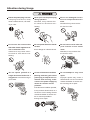
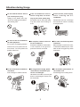
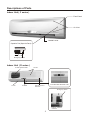
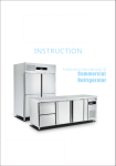
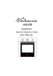
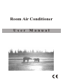
Room Air Conditioner
User
Manual
CONTENTS
Attention during Usage
1-2
Descriptions of Parts
3-4
Remote Controller
5-6
Operation Guide
7
AUTO Operation Mode
8
Air Direction Adjustment
9
Timer Operations
10
Sleep Operation
11
Emergency Operation
12
Installation Master Plan
13
Installation of Indoor Unit
14-15
Installation of Outdoor Unit
16
Connection of Pipe and Electric Cable
17
The step and diagram of Collect refrigerant
18
Electrical Wiring Diagram
19-20
Attention during Usage
Ensure the power plug is secure
Never pull out the power plug
Never use damaged electric
If the plug is not secure, it may
wires or unspecified electric
cause a electric shock, over-heat-
during operation.
otherwise, it may cause a elec-
ing or a fire.
tric shock or a fire due to over -
wires.
otherwise it may cause a elec-
heating.
tric shock or a fire.
Do not operate when the hands
Do not insert a rod or other objects into the inlet or outlet
vents.
Do not use the same socket
with other electric appliances or
are wet.
use an extension cord.
otherwise it may cause a elec-
due to danger of a electric shock.
otherwise, it may cause a electric shock or a fire.
tric shock or a fire due to overheating.
Do not expose yourself to a
In case of abnormal condition
Do not attempt to carry out a
single directional airflow for a
long period to avoid harming to
(burning smell etc.),pull out the
your health.
ditioner from running, or dis-
repair.
Improper repairs may cause a
electric shock or a fire. You should
power plug to stop the air conconnect the power supply by
means of a electric current
protector.
If the abnormal condition persists,
it may cause a electric shock or a
fire due to over-heating. Please
consult the dealer of service centre as soon as possible to
arrange for a repair.
OFF
1
contact the dealer of service centre to arrange for a repair.
Attention during Usage
Do not hold the electric wire to
pull out the power plug.
Pulling of the electric wire may
cause over-heating of the electric
wire causing a fire.
If the air-conditioner is not in
use for a long time, it is necessary to pull out the power plug.
Excessive dust on the power plug
may also cause over-heating or
a fire.
Switch off the power supply
while cleaning the airconditioner.
Please take care not to damage
the internal fan which is rotating
at a high speed.
OFF
Do not use the air-conditioner
for other purposes.
Do not use it for keeping precision
Do not place a heater in front of
the air-conditioner.
instruments, food, plants and ar-
If internal combustion of the heater
is not complete, it may give out
tistic items. This may affect the
poisonous carbon monoxide.
quality of the food.
The room should be kept wellventilated.
When a heater is used in the room,
it should be noted that poor ventilation or lack of oxygen may cause
head-ache.
Do not clean the air-conditioner
For long period of usage, please
with water.
Due to danger of electric shocks.
check that the installation platform is not damaged.
Otherwise the outdoor unit may fall
down or be damaged. Please contact the dealer.
2
Do not climb or place articles on
the outdoor unit
avoid being hurt on falling down.
Descriptions of Parts
Indoor Unit ( C series )
Front Panel
Air Inlet
Vertical Louver
Operation Part (Open the Panel)
Emergency Switch
Indoor Unit ( D series )
Air Filter and Dust Filter
Air Inlet
COOL HEAT
Louver
Air Outlet
DRY
TIMER
COOLING AND HEATING TYPE
Remote Control
Receiver
Emergency Switch
8000Btu/h, 9000Btu/h,
12000Btu/h
3
Descriptions of Parts
Indoor Unit ( G series )
C
A
Auto operation mode
Cooling operation mode
Heating operation mode
Dehumidifying operation mode
Swing
CLOCK or TEMPERATURE display
C
Displays when
turns to CLOCK status
Displays when
turns to TEMPERATURE status
SLEEP
Outdoor Unit
Air Inlet
Connecting Pipe
Drainage Hose
Air Outlet
Drainage Hole
The figures of indoor unit and outdoor are only simple presentation of the appearance of the application;
it may not conform with actual one your purchased.
4
Remote Controller
Signal Emitter :
Sending out remote control signal
to the air-conditioner
Temperature Adjustment Button :
Adjust temperature settings
Press once to set temperature 1
degree higher.
Press once to set temperature 1
degree lower.
Remote Controller Display Panel :
Display settings
COOL
TEMP
Mode Button :
Select Automatic, Heating, Cooling,
De-humidifying, Fan modes
O
C
On/Off Button :
Press once to start Air-conditioner
running; Press again to stop
running.
AUTO FAN
SWING
ON / OFF
FAN Button :
Air flow setting
MODE
Timer Cancel Button :
Cancel Timer-On and Timer-Off
settings
OFF
ON
Timer On Button : Set Timer-on
hour.
TIMER
FAN
CANCEL CONFIRM
Air Direction Button :
Set air louver swinging or stationary
Timer Off Button :
Set Timer-off hour.
SWING
SLEEP
Timer Confirm Button :
Send Timer-on or Timer-off data to
the air-conditioner
FRESH
Fresh Air Button :
Press once to switch on
air-conditioner partner; Press again
to switch off air-conditioner partner.
(There is no this function in this unit)
Sleep Button : Set Sleep Mode
No heating mode for cooling-only type air-conditioner
When controlling the air conditioner with a remote controller, please point the emitter of the
remote controller towards the receiver on the air-conditioner.
5
Remote Controller
Sleep Display :
It indicates Sleep Mode setting
Emission Indicator :
This symbol flashes once when the
Remote Controller emits signals to
the air-conditioner.
Temperature Display :
It displays the current set temperature which may be adjusted by Temperature Adjustment Button
or
within the range of 18 ~30 oC. In Automatic Mode, temperature is not displayed but " Standard " (standard)
temperature + 2oC) or " Standard "
(standard temperature -2 oC) is
displayed.
O
C
Mode Display :
Press "Mode" button to display the
current working mode. Automatic,
Cooling, Dehumidifying, Fan modes
may be selected for cooling-only
types.
Automatic, Cooling,
Dehumidifying, Fan, Heating modes
may be selected for cooling-heating
types.
Timer Display :
It displays the time setting for TimerOn or Timer-Off in the range of 1~12
hours.
FAN Display :
It displays the current amount of air
flow.
FAN
Automatic
Display on
Remote Controller
Fresh Air Display :
When "
" is in display, air-conditioner partner is running. When the
display disappears, air-conditioner
partner is off. (There is no this function in this unit)
AUTO FAN
Low
FAN
Mid
FAN
High
FAN
Air Direction Display :
When "Swing" is in display, the updown louver of the air-conditioner is
swinging. When the display
disappears, the up-down louver
stops swinging.
NOTE:
All Displays on the diagram are listed out for demonstration. During operation, only the
relevant Display will appear on the Remote Controller.
6
Operation Guide
Proper settings of Heating, Cooling, Dehumidifying and Fan modes
Mode Selection ( 1 )
Press "Mode" button to select the required working mode, which is
changed in the following sequence when pressed once:
Automatic
Cooling
Dehumidifying
Fan
Heating
COOL
TEMP
NOTE:
Heating mode is available only on cooling-heating type air conditioner.
Automatic operation will be explained in detail on next page.
3
O
C
AUTO FAN
Air Flow Selection ( 2 )
SWING
Press "FAN" button to select the required amount of air flow,
which is changed in the following sequence when pressed once :
Automatic
Low
Mid
MODE
1
High
FAN
NOTE:
When Automatic FAN is selected, the air-conditioner will automatically select the suitable amount of air flow according to room temperature.
When Dehumidifying is selected, the amount of air flow is set by the machine and fan
setting is not functional.
Temperature Setting Selection ( 3 )
Press "Temperature Adjustment Button " to set temperature 1
degree higher.
Press "Temperature Adjustment Button " to set temperature 1
degree lower.
Hold down the Button to increase or decrease the temperature
settings progressively.
NOTE:
Range of adjustable temperature settings : 18oC ~ 30oC.
Starting Operation ( 4 )
Press "On/Off" button, and when the unit receives the signal, it gives
out two "beep" tones, the operation light is on and the air-conditioner starts operation.
NOTE:
If it is desired to run the machine at the same settings for mode, air flow and temperature
as the last operation, skip Steps 1~3 and start the machine directly.
If the interval is shorter than 3 minutes from last shut down to the present switch-on, the
compressor only re-starts after 3 minutes to protect the system.
After switching on and if the mode is changed, the system may delay for 3 minutes before
starting operation.
When heating mode is selected, the internal fan will delay operation for a while when the
machine is switched on to prevent cool air circulation at the beginning.
After switching on, air flow amount and temperature may be separately adjusted as desired.
7
2
ON / OFF
OFF
ON
TIMER
CANCEL CONFIRM
SWING
SLEEP
FRESH
4
AUTO Operation Mode
Automatic operation Mode
Mode Selection (1)
Press "Mode" button to select Automatic Operation mode.
AUTO
Fan Selection (2)
TEMP
Press "FAN" button to select the required amount of air flow,
which is changed in the following sequence when pressed once :
Automatic
Low
Mid
AUTO FAN
High
SWING
NOTE:
When Automatic FAN is selected, the unit will automatically select the suitable amount of
air flow according to room temperature.
MODE
ON / OFF
OFF
1
Starting Operation (3)
2
ON
TIMER
FAN
Press " On/Off " button, and when the unit receives the signal, it
gives out two " beep " tones, the operation light is on and the airconditioner starts operation is automatic mode.
3
CANCEL CONFIRM
SWING
SLEEP
FRESH
NOTE:
In automatic mode, the air-conditioner automatically selects "Heating" (for heating-cooling
type), "Cooling", "Fan" modes depending on room temperature, with details as the following table:
Temperature
o
o
o
o
< 20 C
20 C ~ 26 C
> 26 C
Cooling
Fan(low)
Fan
Cooling
Heating pump
Heating
Fan
Cooling
Model
NOTE:
On cooling, the standard temperature setting is 26oC. On heating, the standard temperature setting is 20oC.
In the event of discomfort, adjustment may be set by means of the remote controller.
Adjustment in Automatic Mode
Feeling
Button
Operation
Temperature setting may be lowered by
2oC if a bit hot
TEMP
Press once, displaying
Temperature setting may be raised by 2 oC
if a bit cool
TEMP
Press once, displaying
Unsuitable fan speed
FAN
8
Press once to change the air flow progressively until the suitable air flow is
selected.
Air Direction Adjustment
Up-Down Air Direction Adjustment
To set up-down air-louver automatically
swinging :
While the air-conditioner is running, press
"Air Direction" on the remote controller
which displays "Swing", and then the updown air louver automatically swings.
COOL
TEMP
O
C
AUTO FAN
To stop up-down air-louver swinging :
Press "Air Direction" on the remote controller and the "Swing" display disappears,
and then the up-down air louver stops
swinging.
SWING
MODE
NOTE:
To stop the up-down air louver in a desired position, set the louver to automatic swinging and
when it reaches the desired position, stop the louver from swinging. It is necessary to adjust
the louver angle by means of the remote controller, Setting of the louver with the hand may
affect its normal operation, in which event, switch off the unit temporarily and re-start operation.
To get the best effect, the up-down air flow is usually set in the following manner :
Cooling, Dehumidifying - Horizontal air direction or upward air direction. Cooling Downward air direction
Changing Left-Right Air Direction
Move the knobs to adjust leftright air direction
(one knob each on left and right
sides)
9
FAN
ON / OFF
OFF
ON
TIMER
CANCEL CONFIRM
SWING
SLEEP
FRESH
Timer Operations
Timer Switch On
1. Press "Timer On" button to set time for timer-on switching. Press
the button once to change the time interval of 1 hour in a cyclic
manner of 6, 7, 8 ...12 ..1, 2..5, 6 (The display is showing the
previous time as the starting time of the present setting)
If the button is held down, the time interval will increase progressively by 1 hour unit.
2. Point the remote controller towards the receiver on the unit, press
"Timer Confirm" button to send the timer setting to the airconditioner. Then the timer light on the unit lights up, indicating
that the unit is in the timer mode. When it reaches the switch-on
time, the air-conditioner will operate in the pre-set modes.
NOTE:
Before timer operation, please set the operation mode, temperature, air flow etc. on the
remote controller, With timer being set to switch-on mode. the air-conditioner will operate
according to the last setting.
Usually, timer-on setting is made while the air-conditioner is not in operation. If timer-on is
set while the air-conditioner is running, then the unit will shut down immediately and re-start
at the pre-set time.
If the "On-Off" button is pressed while the unit is under timer-on setting, then the unit will start
immediately, the timer setting is cancelled and the timer light will be off.
COOL
TEMP
O
C
HR AFT
ON
AUTO FAN
SWING
MODE
FAN
1. Press "Timer Off" button to set time for timer-off switching. Press
the button once to change the time interval of 1 hour in a cyclic
manner of 6, 7, 8 ...12 ..1, 2..5, 6 (The display is showing the
previous time as the starting time of the present setting)
If the button is held down, the time interval will increase progressively by 1 hour unit.
2. Press "Timer Confirm" button to send the timer setting to the airconditioner. Then the timer light on the unit lights up, indicating
that the unit is in the timer mode. When it reaches the switch-off
time, the air-conditioner will automatically shut down.
NOTE:
Timer-Off can only be set when the air-conditioner is running.
Timer-On and Timer-Off cannot be set at the same time.
Timer display on the remote controller : While time passes, the display shows the remaining
time.
If the "On-Off" button is pressed while the unit is under timer-off setting, then the unit will
shut down immediately, the timer setting is cancelled and the timer light will be off.
Timer Cancellation
Press "Timer-Cancel" button to cancel the timer-on or timer-off
settings.
10
OFF
ON
TIMER
CANCEL CONFIRM
SWING
Timer Switch Off
ON / OFF
SLEEP
FRESH
1
2
Sleep Operation
Press the "Sleep" button on the remote controller, which displays a "
“
symbol, the buzzer gives out a "beep" sound, and the air-conditioner is in a
sleep mode. Press the "Sleep" button again, the "
" symbol disappears,
and the unit is discharged of the sleep mode.
COOL
TEMP
In the sleep mode, when the unit is in cooling or de-humidifying operation,
the pre-set temperature will be raised by 1oC after 1 hour of sleep operation,
and be further raised by 1oC after 2 hours, i.e. totally raised by 2oC in 2
hours, and then keeps on running at this temperature. If the unit is in heating
o
operation, the pre-set temperature will be lowered By 1 C after 1 hour of
o
sleep operation, and be further lowered by 1 C after 2 hours, and further
Lowered by 1oC after 3 hours; totally lowered by 3 oC in 3 hours, and then
keeps on running at this temperature.
The unit will automatically switch off after 7 hours of sleep operation.
However, if the timer-off is also set, then the sleep operation will follow the
timer-off setting. For example, if a 9-hour switch off is set along with sleep
mode, then the unit will run for 9 hours before switching off.
NOTE:
Please set this function during sleeping at night to give better comfort and save electricity.
11
O
C
AUTO FAN
SWING
MODE
FAN
ON / OFF
OFF
ON
TIMER
CANCEL CONFIRM
SWING
SLEEP
FRESH
Emergency Operation
If the remote controller is lost or cannot be used due to battery run-out, please use the "Emergency" button
to switch on the air conditioner.
1. Open the Front Panel
Hold the ridges on the left and
right sides of the unit with
fingers, and pull it up outwards
with a slight force until reaching
the stop position. (about 60 o)
2. "Emergency" Button
Press "Emergency" Button and the air
conditioner gives out a " beep " sound
and starts operation in automatic mode.
Press the button once again to stop
the airconditioner running.
3. Close the Front Panel
Close the panel to original position.
Compulsory Operation
Use this function for installation or test-run only.
1. Ensure that the air conditioner is not used before on being first connected to power supply. If the air
conditioner was operating before, Please disconnect it to power supply and then reconnect on.
Open the front panel by following Step 1 of the above "Emergency Operation".
2. Press "Emergency" button consecutively for 3 seconds, and the air conditioner will give out 3 "beep" tones
3. on being set to compulsory cooling. To stop the air-conditioner, press the button one more time.
Close the front panel.
4.
In compulsory cooling, the air-conditioner will operate for 20 minutes in cooling function disregarding the
ambient temperature before it stops running. During compulsory cooling, the system may be shut down
by pressing "Emergency" button. During operation, the air-conditioner will follow remote controlled
instructions if available.
12
above 3cm but above 8cm
if connect with the pipes
from the side or the back.
Installation Master Plan
Minim
um 1
1cm
Minimum 2cm
Minim
imu
m1
55cm
POWER
Minimum 20cm
Min
um 1
M
u
inim
m1
5cm
Cable Tie
0cm
The left-side must
spacious if only 45
-50cm distance
at back
Mi
ni
m
mu
50
cm
Spanner
Drain
tube
Min
Valve Key
imu
m
35
cm
Liquid valve
1
2
3
4
Gas valve
BLU E
BR OW N
G/
Y
WATERPROOFING COVER
POWER CABLE
SIGNAL CORD
DEFORST CORD
13
Installation of Indoor Unit
Installation of Wall-Hanging Panel
Install the installation panel so that it is correctly positioned vertically and horizontally.
Fix the installation panel at the 5 points shown in the figure with 5 pieces plastic explored screws and
lagging screws. Position the drill-holes by following the routing of the joining hose.
Drill a hole in the wall with the outer side 5-10mm lower than the inner side, in order to have a good
drain flow.
Installation panel
Wall
Plumb line
Pendulum
Piping connection
The piping can be run in the five directions indicated by Right,
Lower, Rear, Left, Left rear in the figure. When the piping is run
in direction Right or Left, cut a notch along the piping groove in
the side of back cover with a hacksaw. When the piping is run
in the direction Lower knock out the flap in the thin wall at the
front bottom of the back cover.
Run the piping in the direction of the wall hole and bind the heat
insulation, connection electric wire with drain pipe at the bottom.
Attention: for the min. bend curve follow the table. Do not force
more min bend radio, as the flexible pipe will be broken.
MODEL
8000, 9000btu/h
12000btu/h
15000, 18000btu/h
24000,28000btu/h
LIQUID
MIN ALLOWABLE
BEND RADIUS
50 mm
GAS
50 mm
LIQUID
50 mm
GAS
80 mm
LIQUID
50 mm
GAS
100 mm
LIQUID
50 mm
GAS
100 mm
FLEXIBLE TUBE
14
Left
Right
Lower
Heat
insulation
Defrost
cable
Connection
electric cable
Left rear
Rear
gas pipe
liquid pipe
Drain Pipe
Connection
electric cable
Installation of Indoor Unit
Indoor Unit Installation
Run the bound pipe and cable through the wall hole and
mount the indoor unit onto the installation panel securely.
Arrange the pipes and cable well.
Flexible pipe
Defrost
cable
Connection
electrical
cable
Drain pipe
Drain Piping
The drain pipe should point downward for easy drain flow.(Fig.1)
Do not make drain piping as shown in Fig.2 to 5.
Accumulated
drain water
Downward
slope
(Fig.1)
Water
leakage(Fig.2)
Air
Water
Waving
leakage
(Fig.3)
Tip of drain
hose dipped
in water.
Less than
5cm gap
Water
leakage
(Fig.4)
(Fig.5)
If the piping runs to the left as shown in the right figure, seal the
drain port on the right with the plug and connect the drain pipe
on the left.
Check that:
1) The top and bottom hooks are hooked firmly.
2) The main unit is accurately positioned horizontally
and vertically. If the unit is not installed properly,
water will drip onto the floor.
3) The drain pipe is not bent upwards as shown in
the figure.
Connect the drain pipe with extension drain hose
If the extension drain pipe has to pass through a room,
be sure to wrap with commercially soil insulation.
15
Drain
pipe
Plug
Drain pipe
Soft house
1.D.15mm
or hard vinyl
chloride
Installation of Outdoor Unit
Placement of Outdoor Unit
Outdoor unit may be mounted concrete slabs raised
above ground level, or on specialist wall mounting
brackets (not supplied).
If unit is mounted at ground level please ensure that it
is raised above ground level so there can be no risk of
unit ever being stood in water.
Outdoor Unit Wiring
Remove the electric box access cover.
Insert the defrost cable into its socket.
Connect the electric cable to the terminal
by the number.
Electric cable
Defrost cable
Defrost
cable
socket
Secure the cables with cable clamp.
Fix back the access cover.
Access
cover
Cable clamp
Electric Cable
16
Defrost
cable
Connection of Pipe and Electric Cable
Piping Connection
Take off the waterproofing cover of the outdoor
unit valve.
Connect the speedy tie-in to the outdoor unit valve.
Tighten them with 2 spanners.
Remove the cap of two valves with the spanner.
Liquid valve
Open the liquid valve and gas valve with valve key.
Tighten the cap of two valves.
Gas leakage inspection:
After connecting the piping,check the joints for
gas leakage,with soapy water or gas leak detector.
Gas valve
Valve key
Finishing
Bind the flexible pipe, electric cable, drain pipe with 5 pieces cable tie.
Make sure to put drain pipe at the bottom.
Drain tube:
Fix the drain tube on the bottom of the outdoor unit to allow drainage of condensation water.
Drainage Test:
Pour a cup or water into the evaporator water tray and ensure that water drains freely from the
drainage hose.
Water tray
Drain
tube
17
The step and diagram for Collect refrigerant (Only to be used if
you intend to move the equipment to new location.)
1. Start the a/c, operate cooling state
2. Remove the cap of two valves with the spanner.
Liquid valve
Gas valve
3. Tighten the core of the liquid valve (the smaller one) with valve key at first. After about 20 seconds, tighten
the core of the gas valve (the bigger one) with valve key. Turn off the a/c at once and cut off the power supply.
Liquid valve
Liquid valve
20 seconds
Valve key
Gas valve
Valve key
Gas valve
4. Tighten the cap of two valves.
Liquid valve
Gas valve
5. Disconnect the power cable from outdoor unit.
6. Loose the nut of the connect pipe to the outdoor unit valve with 2 spanner, disconnect the connect pipe
and and the two valves.
Liquid valve
Gas valve
18
Electrical Wiring Diagram
C series ( Single Split Indoor Unit )
8000Btu/h, 9000Btu/h, 12000Btu/h
Indoor Unit
Power
Step Motor
MS
Outdoor Unit
FM
Fan Motor
Y/G
White
COM
Black
OFAN
CJ4
ROOM
2
2
3
3
4
4
C2
Fan Motor
Capacitor
Compressor
Red
Black
White
S
C CM
R
Y/G
OUTP
INPT
G
CNG
Y/G
R1
G
R2
C1
LED
Temperature
Sensor
Receiving Board
Display Lamp
1
G
White
Yellow
4V
1
Orange
Black
NO
Terminal
Terminal
Y/G
Blue
CJI
Blue
Brown
AC-N
Red
Electrical Box
Blue
YV
Black
CNM
FM
White
PCB
Fan Motor
Four Way
Valve
Copper
Sensor
Compressor
Capacitor
Defrost
Sensor
Defrost Sensor
NOTE:
This electric wiring diagram is only for reference, the correct diagram is on the machine.
G series ( Single Split Indoor Unit )
8000Btu/h, 9000Btu/h, 12000Btu/h
RT2
RT1
STEP
MOTOR
FAN
MOTOR
MS
FM
POWER
TEMPERATURE
SENSOR
5
Outdoor Unit
5
Y/G
PCB
CNE
CN2-1
CNC
NO
COM
BLACK
WHITE
ORANGE
OUTP
RED
1
1
2
2
3
3
4
4
G
C2
Fan Motor
Capacitor
Red
Black
White
White
DISPLAY
RECEIVE
BOARD
10
Terminal
Y/G
Blue
TERMINAL
CNB
Blue
BROWN
OFAN
4WV
Orange
CNU
Red
CNM
Electrical Box
YV
Black
CNG
WHITE
FM
White
AC-NAC-N
Fan Motor
Four Way
Valve
S
C CM
R
Y/G
G/Y
G
TRANSFORMER
Compressor
G
G
C1
Defrost
Sensor
Defrost Sensor
NOTE:
This electric wiring diagram is only for reference, the correct diagram is on the machine.
19
Compressor
Capacitor
Electrical Wiring Diagram
D series ( Single Split Indoor Unit )
8000Btu/h, 9000Btu/h
RECEIVE
BOARD
DISPLAY
BOARD
REV
DIS
3
STEP
MOTOR
SM
Indoor Unit
FAN
MOTOR
POWER
FM
7
Outdoor Unit
5
Four Way
Valve
Y/G
CNB
BLACK 1
WHITE
2
NO
COM
CNC
C2
Fan Motor
Capacitor
2
Compressor
T2
Red
Black
White
3
4
White
Y/G
TRANSFORMER
Y/G
G
1
ORANGE 3
RED
4
CN6
Orange
Terminal
OUT/FAN
Red
Electrical Box
Blue
T1
TEMPERATURE
SENSOR
CN5
ROOM
INPT
WHITE
N
BROWN
L
AC-N
Blue
4WV
FAN
CNM
STEPMOT
YV
Black
CNE
FM
White
CND
Fan Motor
G
G
S
C CM
R
Y/G
G
C1
DEFROST
SENSOR
Defrost
Sensor
Compressor
Capacitor
D series ( Single Split Indoor Unit )
12000Btu/h
RECEIVE
BOARD
DISPLAY
BOARD
REV
DIS
3
7
STEP
MOTOR
SM
Indoor Unit
FAN
MOTOR
Power
FM
Outdoor Unit
5
Y/G
CNB
NO
CNC
COM
T2
CN6
BLACK 1
WHITE
2
C2
Fan Motor
Capacitor
2
Red
Black
White
3
4
G
G
White
Y/G
TRANSFORMER
G
1
ORANGE 3
RED
4
Orange
Terminal
OUT/FAN
Red
BROWN
C1
Compressor
Capacitor
NOTE:
This electric wiring diagram is only for reference, the correct diagram is on the machine.
Compressor
S
C CM
R
Y/G
G
Defrost
Sensor
DEFROST
SENSOR
20
Y/G
Blue
T1
TEMPERATURE
SENSOR
CN5
ROOM
INPT
Electrical Box
AC-N
Blue
4WV
FAN
CNM
STEPMOT
YV
Black
CNE
FM
White
BLUE
CND
Fan Motor
Four Way
Valve