1
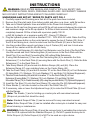
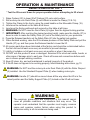
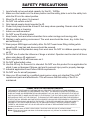
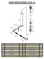
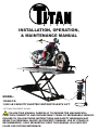
®
INSTALLATION, OPERATION,
& MAINTENANCE MANUAL
MODEL:
1500XLT-E
1,500 LB CAPACITY ELECTRIC MOTORCYCLE/ATV LIFT
*OPTIONAL EQUIPMENT SHOWN
FOLLOW THIS MANUAL CAREFULLY TO ENSURE THE MACHINE WILL
FUNCTION CORRECTLY AND PROVIDE MANY YEARS OF DEPENDABLE SERVICE.
FAILURE TO FOLLOW THESE INSTRUCTIONS AND SAFETY WARNINGS MAY
RESULT IN PERSONAL INJURY OR PROPERTY DAMAGE. USE OF STRAPS IS
RECOMMENDED - SOLD SEPARATELY. KEEP THIS MANUAL IN A SAFE DRY
PLACE FOR FUTURE REFERENCE.
1
®
TITAN MARKETING, LLC
PO Box 7069 Greenwood, IN 46142
1.888.908-4826 FAX (317) 215.2770
www.titanlifts.com
To Our Valued Customers:
Thank you for purchasing a Titan Lifts® product. We hope this high quality equipment provides you with years of
dependable service.
It is unfortunate that rare situations may occur with the products you purchase from Titan Lifts®. We value your
business as well as the trust you have and need to maintain your relationship with us. Titan Lifts® carries liability
coverage that may protect our customers if a situation does occur. However, as in all accidents there must be
proof of liability for a claim to be made. Our insurance company requires the following procedures be observed in
order to consider a claim:
A. The claimant must contact the Titan Lifts® distributor immediately with the facts of the situation.
B. If any equipment is damaged, including vehicles or shop equipment, Titan Lifts® must be given the
opportunity to send and impartial representative to the site for proper assessment of the situation.
C. The Vehicle cannot be moved until either an impartial representative has reviewed the accident or clear
and precise pictures are taken that reflect all the pertinent information for an impartial representative to be able
to access the information from a distance. Titan Lifts® or its representatives must approve the pictures before
anything can be moved.
D. If any potential liability is determined on behalf of Titan Lifts®, two estimates must be submitted for
damages to be reimbursed.
It is imperative that the claimant complies with these procedures, because without proper assessment of the
situation a claim will be denied.
ARBITRATION NOTICE
The installation or use of this equipment shall constitute an acknowledgement that the user agrees to resolve any
and all disputes or claims of any kind whatsoever, which relate in any way to the equipment, by way of binding
arbitration, not litigation. No suit or legal action may be filed in any state or federal court. Any arbitration shall be
governed by the Federal Arbitration Act, and administered by the American Mediation Association, Indianapolis
Indiana. The maximum amount that an arbitrator may award and all damages shall not exceed the retail value of
this equipment.
WARRANTY NOTICE
This equipment must be installed by a “Professional Installer” assembled and used in the manner according to
the documentation provided to be covered by warranty.
Damaged or missing components must be reported within 72 hours of receipt to your freight carrier and to the
distributor. Claims must be filed to cover cost.
If you have any questions or if we can be of any further assistance, please don’t hesitate to contact a Titan Lifts®
representative at 1-888-908-4826. Thank you for the opportunity to continue to serve your lift equipment needs.
1
INSTRUCTIONS
WARNING: READ ENTIRE MANUAL AND COMPLY WITH ALL SAFETY AND
SERVICE PRECAUTIONS. DEATH, PERSONAL INJURY AND / OR PROPERTY DAMAGE
MAY OCCUR IF INSTRUCTIONS ARE NOT FOLLOWED CAREFULLY.
UNPACKING AND SET-UP *REFER TO PARTS LIST FIG. 1
1. Carefully unpack the lift making sure that all of the parts have been included.
2. Remove the lift and all parts from delivery pallet and place on a clean, solid flat surface.
3. Take end of black Hydraulic Hose and attach to the Power Unit Assembly (67).
4. Remove the fill cap from the power unit and fill the oil tank reservoir between the minimum
and maximum range on the fill cap dipstick. To fill the oil tank reservoir, the lift must be
completely lowered. Fill the oil tank with a permium quality 1S0-32
or AW-46 Hydraulic oil, or premium quality ATF - Dexron-111/Mercon.
5. Plug the hydraulic power unit into a standard 110V - 120V 60Hz AC outlet. Raise the lift by
pressing the green button on the control panel to expose the top of Casters (22). Note: If
the lift is not raising level, check to make sure that the Wheels (42) are in their tracks.
6. Use the provided Allen wrench and place in top of Casters (22) and turn it clock-wise.
Lower all four casters until the lift rolls freely.
7. If using the Front Extension (9), slide the Front Extension over the front of the Deck Plate.
Use the second and third Connecting Bars (5) and secure to the Deck Plate with the
Quick Pins (3) or use Short Connecting Bar (68) without Side Extensions.
8. If using Side Extensions (7) then use the Connecting Bar (5) to assemble the Side
Extensions (7) to the Deck Plate (8) securing them with the Quick Pins (3). Slide the Side
Extensions (7) to the Deck Plate (8).
9. Take Ramp Stands (43) and screw into Bottom Ramps (44) and (46). Place the
Extension Ramp (47) over matching holes on the Center Ramp (45).
10. Take the Fixed Clamp (10) and bolt to location “B” on the Deck Plate (8) or Front Extension
(9) Using Bolts (11), Washers (12), Lock Washers (13), and Nuts (14) (Optional Equipment).
11. Take the Crank Assembly (69) and bolt to location “C” on the Deck Plate (8) or Front
Extension (9) using Bolts (11), Washers (12), Lock Washers (13) and Nuts (14). Bolt
Moveable Clamp (16) to Crank Assembly (69) using the provided Bolts (70) (Optional Equipment).
12. Insert the Tire Stop (15) onto the Fixed Clamp (10) using the Pin (60) (Optional Equipment).
12. Place Stands (1) on holes located on the end of the Deck Plate (8).
14. If necessary, raise or lower the Adjustment Legs (6) to make the lift Deck Plate (8) level
with the Ramps.
Note: The Stands (1) are for holding up a motorcycle with rear wheel removed.
(Straps not provided but should be used).
Note: Standard Dropout Plate (2) can be removed for easy rear wheel removal.
Note: Roller Dropout Plate (4) can be installed after motorcycle is loaded for easy rear
wheel cleaning or maintenance.
WARNING: Roller Dropout Plate (4) must be removed prior to unloading the motorcycle
from the lift & replaced with the Standard Dropout (2). Do NOT operate motorcycle on
Roller Dropout (4). Roller Dropout (4) is NOT to be used as a dyno device.
2
OPERATION & MAINTENANCE
*REFER TO PARTS LIST FIG. 1
* Test the lift several times for proper operation before attempting to lift a load.
1.
2.
3.
4.
5.
6.
7.
Raise Casters (22) to lower lift off Casters (22) onto solid surface.
Roll motorcycle onto Deck Plate (8) until Wheel is inside the Clamp (10 & 16).
Tighten the Clamp to the tire by using the crank handle on the Moveable Clamp (16).
Load must be centered on the table at all times.
Load must be firmly positioned and secured on the table at all times.
WARNING: Do NOT raise the Deck Plate (8) higher than the highest locking position.
IMPORTANT: After reaching the desired working height, make sure the Handle (27) is
down in order to make the Safety Plate (61) set in the safety lock for your protection.
8. Press the Release Handle to set the Safety Plate (61) into the safety lock position.
9. When finished working, raise the lift to release pressure off the Safety Plate and pull the
Handle (27) up, and then press the Release Handle to lower the lift.
10. All moving parts have been lubricated at the factory and should be re-lubricated before
the first use and at least once every six months to prevent damage.
11. Lightly oil cylinder rod at least once every six months or when it becomes dry.
12. Do NOT use this product if worn or damaged. Examine lift for structural cracks, bends, or
other signs of damage prior to each use. Check all hoses and connections before each
use to ensure proper working condition.
13. Keep lift clean, dry, and well maintained to extend longevity of the product.
14. If the lift does not appear to be working properly, follow bleeding instructions, pg 10.
WARNING: Do NOT load the motorcycle onto Deck Plate (8) with the Roller Dropout
(4) installed. Use the Standard Dropout Plate (2) when loading motorcycle.
WARNING: Handle (27) should be moved down all the way when the lift is in the
raised position and the Safety Support Plate (61) locked so the lift will not lower.
WARNING
The warnings, precautions and instructions in this manual cannot
cover all possible conditions and situations that may occur. The
operator must understand that the operator must supply common
sense and examine caution factors when using this product to
determine safety in all circumstances being used.
3
SAFETY PRECAUTIONS
1. Load should not exceed rated capacity for this lift - 1500lbs
2. Make sure the handle is in the down position and the safety plate is set in the safety lock
while the lift is in the raised position.
3. Move the lift only when it is lowered.
4. Do NOT ride vehicle onto lift.
5. Only trained people should operate the lift.
6. Power Unit pump should be at least 3 feet away when operating. Remain clear of the
lift when raising or lowering.
7. Indoor use recommended.
8. Do NOT move lift while loaded.
9. Keep hands, tools and other extremities from under carriage and moving parts.
10. Maintain a safe working environment. The work area should be clean, dry, clutter free,
and sufficiently lit.
11. Wear proper ANSI-approved safety attire. Do NOT wear loose fitting clothing while
operating lift, long hair and sleeves should be secured.
12. Keep children and bystanders away from work area. Do NOT let children operate or play
on lift.
13. Do NOT use if under the influence of drugs or alcohol. Operator must be alert at all times
when using heavy lift equipment.
14. Never operate the lift with someone on it.
15. Do NOT adjust safety valve.
16. Use this lift only for the work it is intended. Do NOT use this product for an application for
which it was not designed. Misuse can lead to personal injury and/or property damage.
17. Industrial applications must follow OSHA requirements.
18. Do NOT use for aircraft purposes.
19. Have your lift serviced by a qualified repair person using only identical Titan Lifts ®
replacement parts and attachments. This will ensure that the safety of the lift is
maintained.
PLEASE READ THE FOLLOWING CAREFULLY
THE MANUFACTURER AND/OR DISTRIBUTOR HAS PROVIDED THE PARTS LIST AND ASSEMBLY
DIAGRAM IN THIS MANUAL AS A REFERENCE TOOL ONLY. THE MANUFACTURER OR DISTRIBUTOR
DOES NOT MAKE ANY REPRESENTATION OR WARRANTY OF ANY KIND TO THE BUYER THAT HE OR
SHE IS QUALIFIED TO MAKE ANY REPAIRS TO THE PRODUCT, OR THAT HE OR SHE IS QUALIFIED TO
REPLACE ANY PARTS OF THE PRODUCT. THE MANUFACTURER AND/OR DISTRIBUTOR EXPRESSLY
STATES THAT ALL REPAIRS AND PARTS REPLACEMENTS SHOULD BE PERFORMED BY CERTIFIED AND
LICENSED TECHNICIANS, AND NOT BY THE BUYER. THE BUYER ASSUMES ALL RISK AND LIABILITY
ARISING OUT OF HIS OR HER REPAIRS TO THE ORIGINAL PRODUCT OR REPLACEMENT PARTS
THERETO, OR ARISING OUT OF HIS OR HER INSTALLATION OF REPLACEMENT PARTS THERETO.
Product’s Serial Number:____________________________________________________________________
Note: If product does not have a serial number, record the month and year of purchase instead.
Note: Some parts are listed and shown for illustration purposes only, and are not available individually as
replacement parts.
4
PARTS LIST (FIG. 1)
PLEASE MAKE SURE TO CONFIRM THAT ALL PARTS ARE INCLUDED.
5
PARTS LIST CON’T. (FIG. 1)
NO.
DESCRIPTION
QTY
NO
DESCRIPTION
QTY
1
STAND POLE
2
2
STANDARD DROPOUT PLATE
1
40
RETAINING NUT M8
1
41
SAFETY CABLE LOCK BOLT
1
3
QUICK PIN
6
42
WHEEL
4
4
ROLLER DROP OUT PLATE (See Fig. 4)
1
43
RAMP STAND
2
5
CONNECTING BAR
3
44
RAMP-LEFT
1
6
ADJUST LEG
2
45
RAMP-CENTER
1
7
SIDE EXTENSIONS ( RIGHT & LEFT)
2
46
RAMP-RIGHT
1
8
DECK PLATE
1
47
EXTENSION RAMP
1
9
FRONT EXTENSION
1
48
PIN
1
10
FIXED CLAMP (COLOR)
1
49
WHEEL
2
11
BOLT M10*25
10
50
RETAINING RING Φ12
2
12
WASHER Φ10
12
51
PUMP BED-FRAME
1
13
EYE BOLT
4
52
COUPLING RING
1
14
NUT M10
14
53
ELECTRIC HYDRAULIC PUMP
1
15
TIRE STOP (COLOR)
1
54
BLOCK TERMINAL - GREEN
1
16
MOVABLE CLAMP (COLOR)
1
55
EMERGENCY BUTTON - RED
1
17
CYLINDER (See Fig. 2)
1
56
CONTROL BUTTON - GREEN
1
18
RETAINING NUT M16
5
57
HANDLE SLEEVE
1
19
BOLT M16*80
1
58
THREE-PIN PLUG WITH WIRE
1
20
INNER HEXAGON SCREW M16*90
2
59
TOOL BOX
1
21
RETAINING RING Φ20
6
60
WHEEL STOP PIN
1
22
CASTER
4
61
SAFETY SUPPORT PLATE
1
23
BOLT M16*90
2
62
RUBBER VISE PAD - RIGHT
2
24
LINK ROD 1
1
63
RUBBER VISE PAD - LEFT
2
25
INNER HEXAGON SCREW M20*120
2
64
PLASTIC VISE END CAP - BLK
4
26
RETAINING NUT M20
2
65
PLASTIC WHEEL STOP END CAP - BLK
2
27
HANDLE
1
66
VISE HANDLE - PLASTIC
1
28
SPRING
1
67
PUMP ASSEMBLY (See Fig. 3)
1
29
NUT M8
1
68
SHORT CONNECTING BAR
1
30
BUSHING
1
69
CRANK ASSEMBLY (COLOR)
1
31
BASE ASSEMBLY
1
70
BOLT M8*16
4
32
SAFETY LOCK CABLE
1
71
*COMPLETE VISE ASSEMBLY (COLOR)
1
33
SAFETY LATCH
2
72
SCREW M4*15
4
34
LINK ROD 2
1
73
BOLT M10*20
2
35
NUT M8
1
74
LOCK WASHER Φ10
2
36
WASHER Φ8
8
75
COUPLING BOLT
1
37
LOCK WASHER Φ8
8
76
O-RING
1
38
BOLT M8*20
6
77
DUST CAP
1
39
ADJUST SCREW
1
*OPTIONAL EQUIPMENT
6
RAM PARTS DETAIL (FIG. 2)
NO.
DESCRIPTION
QTY
NO
DESCRIPTION
QTY
1
RAM COVER
1
12
CYLINDER CASING (GREY)
1
2
DUST SEAL
1
13
WASHER
2
3
BACK-UP RING
1
14
FILLER NET
1
4
SPRING COLLAR
1
15
RELEASE VALVE
1
5
PISTON ROD
1
16
BALL
1
6
O-RING
1
17
ADAPTER FITTING
1
7
PISTON HEAD
1
18
90 DEGREE FITTING
1
8
PISTON RING
1
19
O-RING
1
9
SEAL GASKET
1
20
HYDRAULIC HOSE
1
10
OIL SEAL
1
21
HYDRAULIC HOSE FITTING
1
11
ROUND NUT
1
22
DUST CAP
1
7
POWER UNIT (FIG. 3)
NO.
DESCRIPTION
QTY
NO
DESCRIPTION
QTY
12
WASHER Φ10
1
57
HANDLE SLEEVE
1
49
WHEEL
2
58
THREE-PIN PLUG WITH WIRE
1
50
RETAINING RING Φ12
1
72
SCREW M4*15
4
51
PUMP BED-FRAME
1
73
BOLT M10*20
2
52
COUPLING RING
1
74
LOCK WASHER Φ10
2
53
ELECTRIC HYDRAULIC PUMP
1
75
COUPLING BOLT
1
54
BLOCK TERMINAL - GREEN
1
76
O-RING
1
55
EMERGENCY BUTTON - RED
1
77
DUST CAP
1
56
CONTROL BUTTON - GREEN
1
8
ROLLER DROP-OUT PARTS DETAIL (FIG. 4)
NO.
DESCRIPTION
QTY
01
DROPOUT PLATE (COLOR)
1
02
RETAINING NUT M8
4
03
BEARING
4
04
ROLLER
2
05
PIN
2
06
BUSHING
4
9
CHECKING & FILLING HYDRAULIC FLUID
1. Lower the lift completely. Remove the fill cap.
2. The oil level should be even within the minimum and maximum range on the fill cap
dipstick.
3. If the fluid level is low, add premium quality ISO-32, AW-46 hydraulic oil or premium
quality ATF-DEXRON-111/Mercon only. Do NOT use any other fluid or
brake fluid.
BLEEDING
Note: If the lift appears not to be working properly, it may be necessary to bleed
trapped air from the hydraulic system.
1.
2.
3.
4.
5.
Check fluid level. Replace Fill Cap.
Depress and hold release handle.
Press the button to raise the lift while depressing the release handle.
Let up on release handle.
Raise the lift. If the lift does not elevate smoothly, repeat steps 2-5.
10
®
TITAN MARKETING, LLC
PO Box 7069 Greenwood, IN 46142
1.888.908-4826 FAX (317) 215.2770
www.titanlifts.com
Copyright © 2010 by Titan Marketing, LLC. All rights reserved. No portion of this manual or any artwork contained herein may be
reproduced in any shape or form without the express consent of Titan Marketing, LLC. Diagrams within this manual may not be
drawn proportionally. Due to continuing improvements, actual product may differ slightly from the product described herein. Tools
required for assembly and service may not be included.
11