1
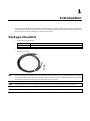
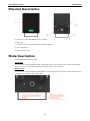
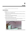
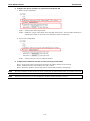
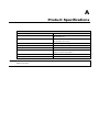
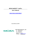
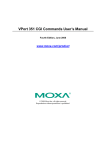
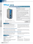
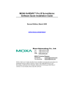
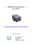
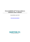
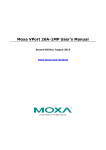
Moxa VP-IR2 Series User’s Manual Third Edition, August 2015 www.moxa.com/product © 2015 Moxa Inc. All rights reserved. Moxa VP-IR2 Series User’s Manual The software described in this manual is furnished under a license agreement and may be used only in accordance with the terms of that agreement. Copyright Notice © 2015 Moxa Inc. All rights reserved. Trademarks The MOXA logo is a registered trademark of Moxa Inc. All other trademarks or registered marks in this manual belong to their respective manufacturers. Disclaimer Information in this document is subject to change without notice and does not represent a commitment on the part of Moxa. Moxa provides this document as is, without warranty of any kind, either expressed or implied, including, but not limited to, its particular purpose. Moxa reserves the right to make improvements and/or changes to this manual, or to the products and/or the programs described in this manual, at any time. Information provided in this manual is intended to be accurate and reliable. However, Moxa assumes no responsibility for its use, or for any infringements on the rights of third parties that may result from its use. This product might include unintentional technical or typographical errors. Changes are periodically made to the information herein to correct such errors, and these changes are incorporated into new editions of the publication. Technical Support Contact Information www.moxa.com/support Moxa Americas Moxa China (Shanghai office) Toll-free: 1-888-669-2872 Toll-free: 800-820-5036 Tel: +1-714-528-6777 Tel: +86-21-5258-9955 Fax: +1-714-528-6778 Fax: +86-21-5258-5505 Moxa Europe Moxa Asia-Pacific Tel: +49-89-3 70 03 99-0 Tel: +886-2-8919-1230 Fax: +49-89-3 70 03 99-99 Fax: +886-2-8919-1231 Moxa India Tel: +91-80-4172-9088 Fax: +91-80-4132-1045 Before Getting Started Before using your VP-IR2, read the following information: The VP-IR2 is designed for the following applications: 1) For use with Moxa VPort series IP cameras to enhance night view images. 2) For use independently as an illuminator. To prevent damage or problems caused by improper use, read this user’s manual before operating the device and peripherals. If you experience a system error, and the system cannot be recovered, please contact your local distributor. Table of Contents 1. Introduction ...................................................................................................................................... 1-1 Package Checklist ............................................................................................................................... 1-1 Physical Description ............................................................................................................................ 1-2 Mode Description ................................................................................................................................ 1-2 Dimensions (unit = mm) ..................................................................................................................... 1-3 2. Usage ................................................................................................................................................ 2-1 Installation ........................................................................................................................................ 2-1 A. Product Specifications ....................................................................................................................... A-1 1 1. Introduction The VP-IR2 series IR illuminator is designed specifically to work with Moxa VPort series IP cameras. It features high power efficiency and a long LED life cycle, and is suitable for all types of industrial surveillance applications. The VP-IR2 can be easily mounted on a VPort camera housing. Package Checklist • NOTE VP-IR2 series IR illuminator Model Name Description VP-IR22080 Infrared LED illuminator, 20°, 850 nm, 12 VDC, 60 to 100 m effective range VP-IR26080 Infrared LED illuminator, 60°, 850 nm, 12 VDC, 20 to 50 meter effective range • Nut and bolt for mounting the VP-IR2 to a VPort camera housing • Power and I/O cable Moxa’s VP-IR2 Series is shipped with the mounting bracket attached to the body. When installing the VP-IR2, use an appropriate screw to attach the VP-IR2 mounting bracket to a wall, or use the provided nut and bolt to attach the VP-IR2 mounting bracket to an appropriate device or frame. NOTE Check the model name on the VP-IR2’s side label to verify that you received the model you ordered. NOTE This product must be installed in compliance with your local laws and regulations. Moxa VP-IR2 Series Introduction Physical Description A: Front cover, made with PMMA protective material B: Main body C: Protective cover for the DIP switch and sensitivity adjuster D: Power & Signal I/O E: Photo cell light sensor Mode Description The VP-IR2 series supports 2 modes. Active mode The Illuminator will be switched On or Off automatically based on the reading of the internal photocell light sensor. The user can adjust the sensitivity of the light sensor on the back panel. Passive mode The Illuminator will be switched On or Off based the camera’s I/O signal. In this mode, the illuminator can be controlled by the camera’s built-in light sensor. 1-2 Moxa VP-IR2 Series • Introduction Switch for Active/Passive mode: When the switch is in the ON position, it is in Active mode. When the switch is in the 1 position, it is in Passive mode. • Sensitivity adjuster for light sensor: The adjuster can be set to any value between 3 Lux and 200 Lux: • 3 Lux: Rotate to the maximum clockwise () position • 200 Lux: Rotate to the maximum counterclockwise () position Dimensions (unit = mm) 1-3 2 2. Usage In this chapter, we describe how to install and synchronize the VP-IR2. Installation The VP-IR2 IR illuminator is usually used together with a Moxa CCTV camera. The VP-IR2 can be installed in the following ways: 1. Mounted to a wall (use an appropriate screw) The VP-IR2 comes with a mounting bracket (already attached) that can be mounted to a wall. Use an appropriate screw to mount the unit to a wall and then connect the power and I/O cable to the camera that the VP-IR2 will be used with. 2. Mounted to a pole (use an appropriate pole mount kit) To mount the VP-IR2 to a pole, choose a pole mount adapter that is suitable for the size of the pole, and then mount the VP-IR2 to the adapter. 3. Mounted to a VP camera housing and VPort camera Use the nut and bolt included in the package to attach the VP-IR2 to a VP camera housing. The following example illustrates how to install the VP-IR2 to a VP-CI701 housing and VP-CI800 bracket. a. Install the VPort camera in the VP-CI701 camera housing. b. Pull the VP-IR2’s power and I/O cable through the VP-CI800 bracket. The end of the cable with loose electric wires should be pulled out from the top of the bracket, as illustrated in the following photograph. c. Pull the wire end of the cable into VP-CI701 housing through the waterproof connector at the bottom of the VP-CI701’s housing. Completely tighten the waterproof connector after the cable is pulled through. Moxa VP-IR2 Series Introduction 4. Connect the power wires to the power source, and the I/O wires to the VPort camera There combination Power - I/O cable has 6 wires. Color of Wire Connection Function Red 12 VDC power + With a 12 VDC power input, the power consumption is about Black 12 VDC power - 10 watts. Blue Alarm input + In Passive mode, connect with VPort’s Relay to switch the White Alarm input - illuminator to ON or OFF. Yellow Alarm output + In Active mode, connect with VPort’s DI to switch the VPort to Green Alarm output - DAY or NIGHT mode. a. Passive mode connection: Step 1: Turn the Active/Passive mode switch to 1. Step 2: Connect the alarm input + (blue wire) with the Relay’s NO (normal open) pin. Step 3: Connect the alarm input – (white wire) with the Relay’s C (common) pin. b. Active mode connection: Step 1: Turn the Active/Passive mode switch to ON. Step 2: Connect the alarm output + (yellow wire) with the DI’s IN (+) pin. Step 3: Connect the alarm output – (green wire) with the DI’s ⊥(ground) pin. 1-2 Moxa VP-IR2 Series Introduction 5. Configure the VPort’s operation to synchronize with the VP-IR2 a. Passive mode configuration: Step 1: Configure the VPort’s light sensor. Step2: Enable the “Trigger relay output when day/night mode switch”. The relay status should be in “Deactivated” status for day mode, and “Activated” status fir night mode. b. Active mode configuration: Step 1: Configure the DI control to “High/Low Switch”. 6. Complete the installation with the VP camera housing and brackets. Step 1: Close the VP-CI701’s housing and mount the VP-CI800’s bracket on the housing. Step 2: Install the housing and bracket on the wall or panel. Step 3: Attach the VP-IR2 to the housing with the nut and bolt provided in the package. NOTE Be sure to install the VP-IR2 onto the VP-CI701 housing and VP-CI800 bracket before you install it on the wall. NOTE Follow the same process if you are installing the VP-IR2 to another housing or camera. 1-3 A A. Product Specifications VP-IR2 Series Infrared Wavelength 850 nm Angle VP-IR22080: 20° IR Effective Range VP-IR22080: 60 to 100 m VP-IR26080: 60° VP-IR26080: 20 to 50 m Automatic IR On/Off Controlled by internal light sensor, or external I/O Operating Temperature -30 to 60°C (-22 to 140°F) IP Rating IP66 ICR Switching Input: Volt-free relay output Output: 12 VDC drive power NOTE Power Consumption 10 W Power Requirement 12 VDC You can mount multiple VP-IR2 IR illuminators pointing in the same direction to increase the illuminated distance and area.