1
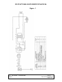
HLS-250
250-Watt Halogen Illuminator
Service Manual
ST Technologies
6018 Bowdendale Avenue
Jacksonville, FL 32216 USA
Customer Service: 904 208 2291
Toll Free 877 814 2237
LIT116 CUDA® SURGICAL
(English)
Rev. B
Date of Revision:08/12/14
Page 1 of 8
250 WATT HALOGEN SERVICE MANUAL
TABLE OF CONTENTS
Page
INTRODUCTION………………………………………………………………….. 3
TECHNICAL SUPPORT SERVICES…………………………………………..… 3
GENERAL THEORY OF OPERATION ………………………………………… 4
FUSE HOLDER REPLACEMENT……………………………………………….. 5
SHUTTER REPLACEMENT………………………… …………………………… 5
LAMP HOLDERE REPLACEMENT ………………………………………………6
TRANSFORMER REPLACEMENT ……………………………………………… 6
COOLING FAN REPLACEMENT…………………………………………………. 6
REPLACEMENT PARTS ………………………………………………………… 8
Figure 1. ……………………………………………………………… …………… 7
LIT116 CUDA® SURGICAL
(English)
Rev. B
Date of Revision:08/12/14
Page 2 of 8
250 WATT HALOGEN SERVICE MANUAL
INTRODUCTION
This manual has been prepared to aid in the repair and maintenance of the 250-Watt
Halogen Illuminators.
The procedures and instructions contained in this document are to be used by qualified
technical personnel only. Some procedures may have live exposed circuitry and wiring
which could be hazardous if contacted with. Use extreme caution when working on
equipment that has power applied to it.
TECHNICAL SUPPORT SERVICES
In the event that you experience difficulty or need technical assistance, please
contact our technical support staff at (904) 208-2291 or toll free at (877) 8142237.
Please have the following information ready when you call:
•
Model number
•
Serial number
•
Detailed description of the problem
LIT116 CUDA® SURGICAL
(English)
Rev. B
Date of Revision:08/12/14
Page 3 of 8
250 WATT HALOGEN SERVICE MANUAL
GENERAL THEORY OF OPERATION
The 250-watt halogen illuminator general operation is as follows. Please consult
Figure 1 for wiring information.
A.C. POWER DISTRIBUTION
The 250-watt halogen illuminator is based around a selectable input transformer.
Input line voltages of 115V ~ at 50/60 Hz and 230V~ at 50 Hz are applied at the
power input model via a hospital grade power cord. Over-current protection is
provided by two 3-amp fuses. A double-pole interlock switch located on the front
right side of the lamp heat shield, provides operator safety.
INTENSITY CONTROL
A rotating stainless steel disc that is placed in front of the lamp controls intensity.
The disc contains holes in varying sizes and patterns. Manual lamp intensity
control is made via a front panel mounted knob.
COOLING SYSTEM
Cooling is provided by a 53FM, 115 VAC fan. Air is drawn through the sides of
the unit, across the transformer and lamp, and exhausted through the rear
mounted exhaust louver. Caution should still be used, as there are still potentially
hazardous temperatures at the turret.
PARTS REPLACEMENT PROCEDURES
The following procedures are meant to aid the technician/engineer in replacing
defective or damaged components. These procedures are meant to be used by
qualified personnel only. Extreme caution should be used and all necessary
safety precautions taken when working on this equipment.
LIT116 CUDA® SURGICAL
(English)
Rev. B
Date of Revision:08/12/14
Page 4 of 8
250 WATT HALOGEN SERVICE MANUAL
FUSE HOLDER REPLACEMENT
1.
2.
3.
4.
6.
7.
Disconnect the illuminator from the power source.
Remove the 8 cover screws of the unit.
Remove top cover. Set aside.
Remove the defective circuit breaker and replace with the new one.
Replace the top cover.
Replace the 8 cover screws and secure.
SHUTTER REPLACEMENT
1.
2.
3.
4.
Disconnect the illuminator from the power source.
Remove the 8 cover screws in the sides of the unit.
Open lamp access door and remove from unit.
Remove the lamp and loosen the screws on the bottom of the lamp
holder. Remove the standoffs and shield.
5. Remove the screw holding the shutter to the front panel.
6. Pull off the shutter assembly.
7. Replace the shutter assembly with the new one.
8. With the control turned fully clockwise, align the shutter in such a way that it
does not cover the hole in the front panel. Replace the screw and tighten the
screw until it holds the shutter in place and still allows for free movement of
the shutter. Do not over tighten the screw.
9. Replace the shield and standoffs.
10. Replace the lamp holder and tighten screws, insert lamp and lamp wires
and insert lamp drawer into unit.
11. Replace the 8 cover screws and secure.
LIT116 CUDA® SURGICAL
(English)
Rev. B
Date of Revision:08/12/14
Page 5 of 8
250 WATT HALOGEN SERVICE MANUAL
LAMP HOLDER REPLACEMENT
CAUTION: Before performing this procedure, be sure the unit has cooled to
room temperature.
1. Disconnect the illuminator from the power source.
2. Open lamp access door and remove from unit.
3 Remove the lamp.
4 Loosen screws that hold the lamp holder to the lamp door.
5 Replace lamp holder and fasten with the screws.
TRANSFORMER REPLACEMENT
1.
2.
3.
4.
Disconnect the illuminator from the power source.
Remove the 8 cover screws in the sides of the unit.
Remove the top cover from the unit. Set aside.
Disconnect the fan lead connector, the AC power input connectors, and the
lamp output power wires from the power supply.
5. Set the unit on its side.
6. While holding the transformer with one hand, remove the 4 mounting screws
from the bottom of the unit.
7. Place the new transformer in the unit so all 4 holes line up with the holes in
the chassis. Secure with the 4 mounting screws from the bottom.
8. Place the unit back on its feet.
9. Reconnect the fan lead connector, the AC power input connectors, and the
lamp output power wires to the power supply.
10. Replace the top cover.
11. Replace the 8 cover screws and secure.
COOLING FAN REPLACEMENT
1.
2.
3.
4.
5.
6.
7.
8.
9.
Disconnect the illuminator from the power source.
Remove the 8 cover screws of the unit.
Disconnect the fan lead connector from the transformer.
Remove the fan mounting screws and nuts. This will free the fan louver also.
Replace the fan assembly with the airflow blowing out the back of the unit.
The fan leads should be coming out of the fan at the tip and against the back
panel.
Secure the fan mounting screws with the nuts.
Reconnect the fan lead connector to the transformer.
Replace the top cover.
Replace the 8 cover screws and secure.
LIT116 CUDA® SURGICAL
(English)
Rev. B
Date of Revision:08/12/14
Page 6 of 8
250 WATT HALOGEN SERVICE MANUAL
Figure 1
LIT116 CUDA® SURGICAL
(English)
Rev. B
Date of Revision:08/12/14
Page 7 of 8
250 WATT HALOGEN SERVICE MANUAL
REPLACEMENT PARTS
DESCRIPTION
Lamp holder
250-Watt Transformer
Fuse holder
Cooling Fan
PART NUMBER
001116000
1101516
0011132000
001110001
For parts not listed here, call our Technical Service Department listed at the front of the
manual.
LIT116 CUDA® SURGICAL
(English)
Rev. B
Date of Revision:08/12/14
Page 8 of 8