1
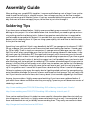
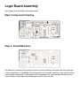
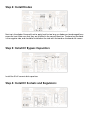
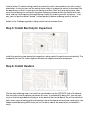
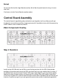
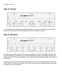
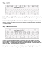
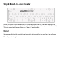
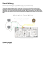
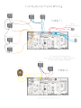
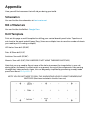
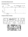
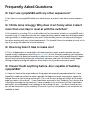
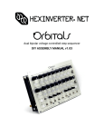
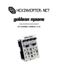
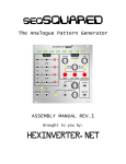
sympleSEQ v2.0
Another simple to build analogue step-sequencer, brought to
you by
HEXINVERTER.NET
electronics projects for musical synthesis
(Assembly and Operation Manual rev.2)
Introduction
Hello, and thank you for your interest in or purchase of sympleSEQ!
This is the build manual for the project. You will find the schematics, as well as an assembly
guide, printable drill template and tips on how to get the most out of sympleSEQ.
This project was born out of a serious lack of simple analogue hardware sequencers available
to build. There are oodles of sequencer designs out there, ranging from simple to complex,
but the actual construction of said devices is usually quite laborious, regardless of the electrical complexity/functionality. By design, a sequencer is a fairly simple device, so this tempts
many people to not use printed circuit boards when assembling one and just build it all on
perf-board. The actual logic circuitry for a sequencer is usually quite easy to understand - especially in the case of a design built around the CD4017 decade counter (known by many as
the “Baby10”) like this one. Where builders encounter hardships however is in the extreme
redundancy of wiring the controls for these devices. Each step in the sequence requires a
potentiometer (knob), toggle switch and LED at minimum. If you have ever soldered wires
to panel components, you probably know how delicate of a process it is -- it would be nice
to have four hands when doing jobs like this, making just a handful of controls take a decent
amount of time and endurance to complete -- let alone 8 or more sets of controls!
The general concensus is that in analogue synthesis, you can never have too many modulation sources. Despite its only providing 8 steps of control voltage, sympleSEQ can still satisfy
many builders with 16 or 32 step sequencers already dedicated to pitch modulation by providing extra modulation sources for filters or anything else you can control via control voltage.
Most of all however, sympleSEQ’s target audience is people new to do-it-yourself (DIY) synthesis. When most people think “analogue synthesizer”, something like Pink Floyd’s famous
tune “On the Run” probably comes to mind. So, it is only natural that nearly every beginner
lusts for the sound of an analogue sequencer. The task of building one for a beginner up until
now has been one of great difficulty for most, due to the lack of documentation and the extreme complexity of wiring such a thing to the panel for use afterwards.
Enter sympleSEQ: using a unique dual-board design, primarily board mount potentiometers,
LEDs and switches, you can build yourself a simple analogue step-sequencer with little electronics knowledge.
Note that sympleSEQ does not do every single thing that a more complex, large and expensive sequencer does. There may be some features you miss (voltage quantizing, forward/back
and other things are not included), but I think all of the essentials are here.
sympleSEQ was made possible only by the extensive online community of creative minds at
the electro-music and Muffwiggler forums. Were it not for people contributing their excellent suggestions on feature enhancements for the prototype design and me trying to satisfy
peoples’ requests, sympleSEQ would be nowhere near the product it is now!
Also, the cost of running such a product was made possible through pre-funding accumulated
by trustworthy individuals who supported the project financially from the beginning!
Of particular mention are those who contributed start-up funding to the project. Seeing only
videos and forum correspondence from me about the project and placing a great amount of
trust into me is something sympleSEQ would not have survived if not for, so I would like to put
out a “thank you” to everyone who placed their financial trust in this project! There is no way I
could have funded the start up cost for this project myself, so it just goes to show what many
people’s small effort can do when summed up together. Without the amazing do-it-yourself
community we have, and the power of the internet, none of this would have been possible! It
is a truly awesome spectacle to see so many unique projects realized with the power of commmunication technology. Thank you all for being a part of it!
If you have not heard, Ben of Re:Synthesis is going to be selling panels to complement this
project directly from him. He is also offering fully assembled modules! Get on board that
project by visiting the forums if you’re a regular there, or contacting him directly: http://www.
resynthesis.co.uk
Anyway, enough of the babbling. Let us get onto the actual manual! If you are looking for
quick facts, check out the FAQ (frequently asked questions) at the back of this manual.
- Stacy Gaudreau, aka Hex Inverter
hexinverter.net Electronics
Table of Contents
(note that all items are interactive - click to be taken to the page)
5: Technical Information
6: Assembly Guide
7: Logic Board Assembly
10: Control Board Assembly
14: Panel Wiring
16: Test/Use It!
17: Mechanical Assembly
18: Appendix (schematics, parts overlay drill template, FAQ
etc.)
Technical Information
Power Supply Requirements:
5-15V DC supply @ ~15mA (per sequencer). sympleSEQ is very forgiving in terms of supply
voltage as it uses CMOS circuitry. Of course the LED brightness will change with the voltage
used, so you may need to adjust resistor values for odd voltages (say 8v or less perhaps?). The
module has been built and tested at 9V and 12V, but should work at pretty much any other in
the stated range. It is a great candidate for being put into a portable unit as it can run from a
9V battery with ease and does not require a dual voltage supply like much analogue gear does.
Control Voltage Output:
There are simultaneous 0-5V and 0-~Vcc CV outputs on the logic board. You can choose to
wire these to a switch to select on the panel, or you can hardwire one (or both) to jacks. If you
only want one level, you can leave the other disconnected.
Gate Output:
The gate will output a positive voltage excursion at around either 5V or 10V, depending on the
output you have selected from the logic board. There are simultaneous 5V and 10V gate outputs. You could wire these to a switch and put a switch on your panel, or you can wire them
to separate jacks and have both available at all times. If you only want one level, you can leave
the other disconnected.
Onboard Clock:
sympleSEQ uses CMOS logic square waves operating at or near the supply voltage for a clock
source. This clock should be useful for driving most other sequencer designs as well, but you
may choose to run sympleSEQ from another more feature rich sequencer’s clock.
CV Pot. Knobs:
Due to sympleSEQ’s extremely compact design, space is very tight on the panel. The maximum knob diameter you can use without mechanical issues is 19mm, but I highly recommend
something more like 13 or 14mm. This entire module is very Eurorack in design, in that it packs
maximum functionality into minimal space. One interesting feature of the Alpha 9mm PCB
mount potentiometers used in this module is their pseudo-knob like shaft. The pots’ shafts
have a nice grippy surface as well as a pointer on them, thus, they function very much like
knobs already! You may choose not to use knobs at all based on this if you wish to save cost/
panel space.
Assembly Guide
When putting your sympleSEQ/s together, I recommend following a set of steps I have synthesized in order to do things in a logical manner. Your mileage may vary, so feel free to experiment and come up with a better system. If you’re a seasoned electronics person, you will probably find most of it does not apply to you, so feel free to just skim through it.
Soldering Tips
If you have never soldered before, I highly recommend doing some research first before embarking on this project. I list a few videos below that should be all you need to get up and running making excellent soldering joints. A decent temperature controlled iron is expected for
you to be able to complete this project. It is possible that you may damage some of the components while soldering them in if you are using a poor quality iron and have to hold the heat
to the joint for too long.
Something I can add that I think is very beneficial: do NOT use sponges as tip cleaners!!! I NEVER use a sponge. Get yourself one of those wire/steel wool looking tip cleaners. I found a pair
for $10 on eBay. There is simply no comparison. A sponge seriously damages your iron. Why?
Well, first of all, when you plunge your nice hot tip into a sponge covered in cool water, it rapidly cools your tip. Metal does NOT like rapid heat changes, and it also causes your tip to cool
off somewhat which makes it work to get back up to operating temperature (if you have a good
iron, you probably won’t notice it, but with a crappy iron it will probably mean you have to wait
after cleaning your tip to get back to soldering!) The number one advantage of using a wire tip
cleaner is the fact that you will pretty much never have to replace your tip due to it not damaging it! Seriously. I have been using the same tip for well over a year, and I am not lying when I
say it is as good as new! I cannot tell it apart from a brand new tip. When I used to use sponges,
I’d have to replace my tip every few weeks due to it getting caked up from the sponge burning
onto it/oxidation/damage. Do yourself a favour and throw out that sponge. They are really inferior! If you have to use one for now, don’t worry about it, but consider upgrading in the future!
Anyway, here are videos I highly recommend watching if you have never soldered before. If
you watch these videos and follow what they are saying, I promise you will become a master of
soldering in no time!
http://www.eevblog.com/2011/06/19/eevblog-180-soldering-tutorial-part-1-tools/
http://www.eevblog.com/2011/07/02/eevblog-183-soldering-tutorial-part-2/
Once you’ve watched those, this video has some specific information about how to install certain components, tips/tricks, so I highly recommend watching it as well. I have watched all of
these and therefore am not just blindly recommending them. They really are excellent videos:
http://tangentsoft.net/elec/movies/tt02.html
Logic Board Assembly
Let us begin with assembly of the logic board:
Main Component Overlay
Step 1: Install Resistors
Pay attention of course to the value of resistor you are installing, and make sure that nothing is
in the wrong place. It is probable that the board will not function correctly if you install a wrong
value resistor somewhere. If you bought a full components kit, your resistors should have the
value written on their tape-reel packaging to make it easier for you.
Step 2: Install Diodes
Next up is the diodes. Be careful not to apply heat for too long, as diodes can be damaged from
excessive heat. Make sure that they are installed in the correct direction. The band on the diode
is the negative side, and should be installed on the side with the band on the board silk-screen.
Step 3: Install IC Bypass Capacitors
Install the 0.1uF ceramic disk capacitors
Step 4: Install IC Sockets and Regulators
Install the four IC sockets, being careful to match the notch’s orientation to the silk-screen’s
orientation. A trick you can use for seating them nicely is to place the socket in the board, flip
the board over so that it’s resting on the socket, and then “tack” only one leg in place. Now,
touch the soldering iron to the one leg while flattening the board onto the socket with your
hand, seating it flush against the board (being careful not to burn yourself, of course) -- that
way, you can get the socket “tacked” in place perfectly before soldering up all of the pins.
Solder in the 3 voltage regulators, being careful not to overheat them.
Step 5: Install Electrolytic Capacitors
Install the remaining two electrolytic capacitors, being careful to note the correct polarity. The
shaded half on the silk-screen legend indicates the negative lead of the capacitor.
Step 6: Install Headers
The last part soldering step is to install the male header into the OPPOSITE side of the board.
You must also install the power connector (or wires, as indicated) By doing this, you are making it so that the logic board will plug in to the back of the control board. So, just to make that
clear: when you are looking at the component side of the board we have been working on, the
header should be facing AWAY from you on the other side of the board when installed correctly.
Done!
You are now finished the Logic Board assembly. We will do the panel/control wiring in its own
step, later.
Continue on to the Control Board assembly, below.
Control Board Assembly
The control board is regretfully pretty redundant to put together, but if you find yourself getting bored, just comfort yourself by imagining how awful it would be to wire all of these parts by
hand! It doesn’t seem so bad now, does it?
Main Component Overlay
Step 1: Resistors
Install resistors R1-R8 which are all 10k current limiting resistors for the LEDs. Note that depending on the colour and intensity of LEDs you have used, you may need to alter this value. If
you did not listen to me and used “normal” LEDs (not “super-bright”s), you may have to greatly
reduce the value of these resistors just to get the LEDs to light. Blue LEDs tend to need more
current than a green LED, and thus need a smaller resistor value to produce the same amount of
intensity. If you are using a kit, you can ignore this part as the resistors should work good with
the LEDs in the kit.
Step 2: Diodes
Install and solder the 16 diodes onto the board, again making sure that they are installed the
correct way. Things will not work properly if they are installed incorrectly.
Step 3: Switches
The switches included in the v2.0 kits are very nice quality ON-OFF-ON toggle switches. They
can be installed in any direction. It is recommended that you place the switches through the
panel to ensure that they are soldered in such that they will actually go through all of the panel
holes easily.
I recommend “tacking” the switches in place while in the PCB, then adjusting them while they
are in the panel, such that they each sit flush with the PCB and are aligned straight when viewing them in a row on the panel.
Step 4: LEDs
Put the 8 LEDs through their LED spacers, then place the LEDs in the board and bend their leads.
The short lead of the LED matches the flat side of the LED on the PCB. This is the negative side of
the LED.
I recommend “tacking” the LEDs in place while in the PCB, then adjusting them while they are in
the panel, such that they each sit flush with the PCB and are aligned straight when viewing them
in a row on the panel.
Step 5: Potentiometers
Install the 8 board mount potentiometers in their places, starting with the outer mechanical
posts and adjusting them using the “tack method” as necessary to make them perfectly flat on
the circuit board. It is crucial that they are aligned accurately so as to go through the panel in the
correct drill spaces. Then, solder up all of the other pins!
Once again, I recommend soldering these while they are protruding through the panel, so that
they are in the correct alignment to go through the panel when everything is assembled.
Step 6: Board-to-board Header
Install the female 12 pin header on the OTHER side of the board (ie: if you are looking at the
board from the component side, the header should be facing away from you on the other side).
This will mean that the Logic Board can “plug-in” from the back.
Done!
You are now finished the control board assembly. Pat yourself on the back for a job well done!
Time for panel wiring!
Panel Wiring
The final step to building your sympleSEQ is to get your panel all wired up!
There are a couple of options which I show here. One is a very minimalistic version which is
excellent for someone just wanting a constantly running sequencer for, say, circuit bending or
something. This has the least amount of effort involved. I don’t recommend it if you want a lot of
control over the sequencer, as you cannot reset/pause the sequencer to maintain sync with other
gear.
(next page)
Test It!
Now that you have assembled your sequencer and wired the panel components, I recommend
testing it before actually installing it in the panel (so you can fix any errors now).
Install the ICs in their sockets and power up.
Patch the Clock Out into the Clock In.
You should now be sequencing! Test the Gates by turning some toggle switches up, and also test
the CV output.
If something is not working right, go back and double check your soldering and wiring! Most of
the time it is simply builder error that causes problems.
Use It!
How to use sympleSEQ
sympleSEQ works quite analogous to most other step-sequencers. Each of the 8 steps has a CV
pot and switch associated with it. The CV pot sets the level of the CV for that step, and the switch
turns the gate for that step on or off, as well as allows you to select a sequence length.
To turn a gate for a step on, turn the switch for that step up. To turn a gate off, set the switch to
the centre position.
You can program the length of the sequence by turning a step switch down.
NOTE: Turning multiple switches to the reset (down) position will cause strange sequencing
behaviour. This is a bi-product of such a simple design. You just have to keep in mind that you
should turn off a reset point before setting a new one in a live setting (that is of course unless you
WANT chaotic behaviour!)
Mechanical Assembly
Well, you have gotten this far, and hopefully the electrical assemblage of your sympleSEQ is
complete and without fault. Now it’s time to finish the project up by putting it in an enclosure
that you would like to use it in. If you have purchased ready-made panels from Re:Synthesis, you
can of course skip the whole drilling step.
I will start off by saying that I highly recommend you have a drill press for this. There are quite a
few holes to drill on sympleSEQ and while it is not impossible with a hand drill, it will be pretty
fatiguing.
Start off by printing out the drill template in the appendix. It has been made such that it is easy
to affix it to your panel and drill the holes for the control board to go through. I will leave it up to
you to locate and drill the positions for tempo, output jacks and any other additional features you
wish to include. Everyone’s configuration will be different, of course.
It is crucial that you try to get the holes as accurate as possible, as all 8 steps of the board need
to fit through the holes nicely.
Once your holes are drilled, it’s just a matter of screwing the 8 step switches’ nuts on to hold the
panel to the board, and installing all of your panel components to the panel!
Now, go make some music!
Appendix
Here you will find resources that will aid you during your build.
Schematics
You can find the the schematics at: hexinverter.net
Bill of Materials
You can find the the BoM at: Google Docs
Drill Template
Print out this page as a drill template for drilling your control board’s panel holes. Tape the cut
out sheet to the panel and drill away! Easy. (there are multiples here to save the number of sheets
you need to print if making multiples)
LED holes: 5mm drill (13/64”)
Pots: 6.35mm drill (1/4”)
Switches: 5mm drill (13/64”)
Mounts: 3mm drill (1/8”) (ONLY NEEDED IF NOT USING THREADED SWITCHES)
Note that you may need to file out some of the holes to account for irregularities in your soldering job on the board. An offset switch may prevent the rest of the components from passing
through their holes perfectly. Again, this can be greatly simplified by purchasing a ready-made
panel from Ben at Re:Synthesis :)
NOTE: YOU DO NOT NEED TO DRILL THE 6 MOUNTING HOLES IF USING THREADED/NUT
SWITCHES! (like those included in the kits from me)
Control Panel Measurements
These measurements will be of use if you are laying out your own panel in some form of computer aided design software.
Component Name Overlays
Frequently Asked Questions
Q: Can I use sympleSEQ with my other sequencers?
A: Yes! You can use sympleSEQ either as a clock source, or clock it from other master sequencers.
Q: I think mine is buggy. Why does it act funny when I select
more than one step to reset at with the switches?
A: This actually is not a bug. This is a side-effect of the minimalistic circuitry in sympleSEQ and is
a known thing. It is important that the user understand they need to undo one reset point before
setting another, or chaotic patterns may result! Unfortunately you can not have everything perfect when working with very limited components. This shouldn’t harm the module to use it in this
way if you enjoy the effect for musical purposes.
Q: How long does it take to make one?
A: This is all dependent on the builder’s skill and experience level, and also whether you purchased a ready-made panel from Ben at Re:Synthesis or not. Generally speaking, you should be
able to complete the electrical assembly in about an hour or two if you are experienced. A beginner will want to carefully follow the instructions, however, and thus it will take a while longer.
Drilling and panel making will add a fair bit of time to this if you did not order a panel!
Q: I haven’t built anything before. Am I capable of building
sympleSEQ?
A: I hope so! You are the target audience this project was originally conceptualized for. I have
(hopefully) made every effort to make it possible for beginners to get themselves a sequential
voltage source to start making sounds with. This is not to say that you will find all of the knowledge you need in this manual -- I have listed other resources in the “Soldering Tips” section that
I strongly encourage you to check out. I have no doubt in my mind that if you are interested in
electronics you are probably smart enough to learn along the way -- this alone should ensure
you will be successful in your assembly. Of course, if you run into problems, me and others are
available to help!