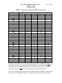
1
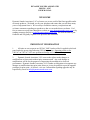
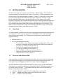
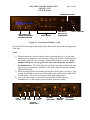
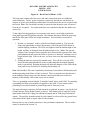
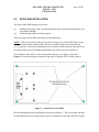
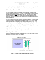
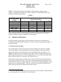
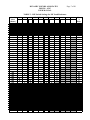
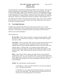
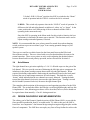
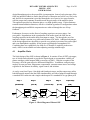
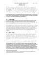
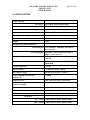
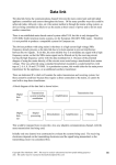
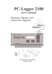
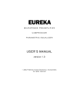
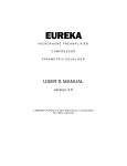
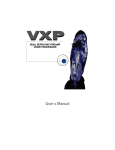
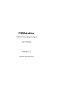
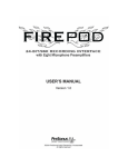
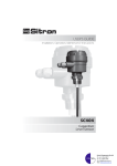
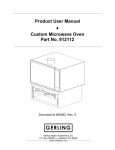
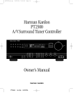
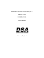
DYNAMIC SOUNDS ASSOCIATES, LLC
PHONO – ONE
USER MANUAL
120 VAC Operation
Potomac, Maryland
DYNAMIC SOUNDS ASSOCIATES
PHONO – ONE
USER MANUAL
WELCOME
Dynamic Sounds Associates, LLC welcomes you to our world of the finest possible audio
electronic products. We thank you for your purchase and ensure that you will have many
years of enjoyment from it. We are always available to answer your questions and
welcome comments regarding our products so that we can make them even better. Feel
free to contact us at any time through our website at www.dynamicsounds-assoc.com or by
sending messages directly to [email protected]. We look forward to your
feedback and will gladly respond to all questions and comments.
IMPORTANT INFORMATION
1.
All units are set to operate on 120VAC ONLY unless a label is applied to the back
panel under the power plug indicating 230VAC operation. Operating a unit set for
120VAC on 230VAC will cause permanent damage and void the warranty.
2.
Dynamic Sounds Associates, LLC reserves the right to make changes or
modifications to future units without prior announcement. Any such changes or
modifications will be for the purposes of improving the mechanical or electrical
performance. Dynamic Sounds Associates, LLC is under no obligation to incorporate any
changes or modifications into prior units; however, it may be possible to provide upgrade
packages for prior units—if desired—at a cost. Information regarding upgrades may be
requested by e-mail to [email protected].
DYNAMIC SOUNDS ASSOCIATES
PHONO – ONE
USER MANUAL
1.0
Page 1 of 20
GETTING STARTED
We know how eager you are to get your new Phono - ONE into play. This section will
provide preliminary information on the features of the Phone – ONE, and familiarize you
with the layout of the controls and the connectors. Section 2.0 will guide you through the
process of setting up the ONE and making the proper connections. Section 3.0 will
provide additional information on the operation and use of the features of the ONE.
Section 4.0 will provide more detailed information on the overall operation and capabilities
of the ONE and can be reviewed at your leisure. Section 5.0 will provide information on
how to balance the outputs of the ONE to maintain its high degree of performance. The
ONE comes pre-balanced and, during normal operation, should not require checking and
changing the output balance more than once/year—if that.
1.1
Unpacking
The ONE should be carefully removed from the packaging material and the plastic bag that
it is wrapped in. Take care not to damage the switch handles on the front panel when
removing from the wrapping. The following items should also be found in the ONE
shipping container:
•
•
1.2
Shielded power cord
Box/bag containing the following –
o 2-“Load cards” for use with moving magnet cartridges (those for use with
moving coil cartridges are already inserted in the ONE prior to shipment)
o 1/16” Hex key wrench (used in Section 5.0)
o 5/64” Hex key wrench (used in Section 2.0)
o 1/8” Hex key wrench (used in Section 5.0)
o #0 -2.5” Philips screwdriver (used in Section 5.0)
o XLR male connector with wires (used in Section 5.1)
o 1Kohm resistor (used in Section 5.2)
First Look at the Phono ONE
After unpacking your ONE and ensuring that all of the parts are provided, you should take
a few moments to familiarize yourself with the features on the front and back panels. The
front panel is shown in Figure 1a, and the back panel is shown in Figure 1b.
The most prominent features on the front panel are the glass logo, which is illuminated
when the power is turned on, and the row of function switches. What these switches do is
covered in detail in Section 3.3. The Standby/Mute/Run switch on the right-hand side
selects the operating mode as follows:
• Standby – amplifier is powered but the output stage is not powered
• Mute – amplifier and output stages powered, but output is muted
• Run
– amplifier is fully operational
DYNAMIC SOUNDS ASSOCIATES
PHONO – ONE
USER MANUAL
Page 2 of 20
Standby/Mute /Run switch
LEDs indicating type of
cartridge and gain settings
as selected on load cards
Function switches
Photodiode for
dimming of front
panel illumination
Power on/ status LEDs
Figure 1a – Front Panel of Phono – ONE
The status LEDs to the right of the Standby/Mute/Run switch indicate the operating mode
of the unit.
Notes:
1) When first turned on (see back panel) it takes approximately 60 sec for the main
amplifier power supplies to reach operating voltage and stabilize. During this time
the Standby LED will show an orange color and will blink at a 1Hz rate. (If the
Standby LED shows a red or green color only, turn off the unit and contact
the manufacturer.) The ONE cannot be switched to the Mute or Run mode until
after the power supplies have stabilized. This will be indicated when the standby
LED stops blinking.
2) When switching between the Standby and the Mute mode, there is a delay of a few
seconds for the ONE to come out of the Standby mode, and before the Mute LED
will illuminate. This is due to the startup delay in the output stages.
3) Once in the Mute mode, switching between the Mute and Run modes is
instantaneous, as is the response when switching from Run to Mute.
Power
cord plug
Fuse
holder
Power
switch
Turntable
ground
Front panel
Dimmer control
Left channel
Input & Outputs
Gain balance
adjustment
Right channel
Input & Outputs
DYNAMIC SOUNDS ASSOCIATES
PHONO – ONE
USER MANUAL
Page 3 of 20
Figure 1b – Back Panel of Phono – ONE
The back panel contains all of the power and audio connections, plus two additional
control functions. The AC power receptacle is on the left, housed in a unit that has an
integral AC power switch and fuse holder that is located between the power receptacle and
the switch. Note: The fuse holder can only be removed when the power cord is removed
from the AC receptacle. Two replacement fuses are contained within the fuse holder (see
section 2.4).
To the right of the integrated power receptacle/switch unit is a switch that controls the
front panel logo and LED dimmer function. This dimmer function will dim the glass logo
and the the front panel LEDs in low light conditions. This switch has two modes of
operation:
1. Normal, or “automatic” mode is with the switch knob pushed in. This uses the
front panel photodiode to control the intensity of the front panel LEDs based on
ambient lighting conditions. The LEDs are brightest when the ambient light is also
bright, and they are dimmed when the ambient light is low. (Note: The spectral
output of some compact fluorescent bulbs does not match the response of the front
panel photodiode and causes the LEDs to operate in a “dimmed” condition even in
bright ambient light. If this is the case, you may want to use the manual dimming
mode.)
2. Pulling the knob out activates the manual mode. This will also cause the LED
above the front panel photodiode to turn on indicating that the manual dimming
mode is operational. Rotating the knob will adjust the intensity of the LEDs on the
front panel to any desired level, including almost totally off.
Note: The Standby LED is not controlled by the dimmer, but remains at full intensity until
another operating mode (Mute or Run) is selected. This is to alert the user that the unit is
in the Standby in those cases where the dimmer control would otherwise reduce the
intensity of the Standby LED so that it may not be noticed.
There is a grounding terminal labeled “Turntable Ground” that is used ONLY for attaching
a grounding lead from your turntable (if supplied) to the ONE. Do not connect other
grounding wires to this terminal or ground loops and AC hum may occur.
The input and output connectors for both channels are gathered in groups—one for the Left
Channel and one for the Right Channel, as shown. Each channel uses a single RCA plug
input but has both an RCA plug (for unbalanced output) and an XLR plug (for balanced
output). The auxiliary ground terminal for each channel is to be used for any ground wires
associated with the input or output cables for that channel.
Between the two sets of audio connectors is the gain balance adjustment. The use of this
control is described in Section 3.4.
DYNAMIC SOUNDS ASSOCIATES
PHONO – ONE
USER MANUAL
2.0
Page 4 of 20
SETUP AND INSTALLATION
The setup of the ONE consists of two steps:
(1)
(2)
Installing the proper Load Card and setting the correct gain and load impedance for
your phono cartridge.
Connecting the cables to the back panel.
These two steps will be addressed in the sections that follow.
NOTE: There is no reason for the user to remove the top cover of the ONE. There are no
serviceable parts within and the Load Cards are accessible without removal of the top
cover. Likewise, all necessary adjustments are accessible without removal of the top cover.
If required, the process for making adjustments to the ONE is given in Section 5.0.
Access to the Load Cards is via an access panel in the top cover plate, as shown in
Figure 2, it is not necessary to remove the top panel. Using the 5/64” hex key, remove
Figure 2 – Load Card Access Panel
the two button-head screws indicated by the arrows in Figure 2. The access panel can then
be lifted from the top cover plate and set aside, revealing the Load Cards on the PC boards
DYNAMIC SOUNDS ASSOCIATES
PHONO – ONE
USER MANUAL
Page 5 of 20
below. After installing the Load Cards per the following sections, the access panel should
be replaced and the two button-head hex screws replaced to secure the panel.
2.1 Installing the Correct Load Card
The correct gain and cartridge load impedance are selected on the “Load card” for the
particular phono cartridge to be used. If possible, it is suggested that the switch settings on
the load cards be selected prior to inserting the load card. The Load Card is a small
printed circuit board (PCB) that plugs into the Phono ONE main PCBs adjacent to the
input cables. There is a Load Card for each channel and it is important that the switches on
each be set identically.
The load card for moving coil (MC) cartridges comes already installed. It is factory set for
51ohms load resistance and 60dB gain. If your phono cartridge is of the moving magnet
(MM) type, remove the MC load card for each channel and insert those for MM. Take
care that the cards are removed by pulling them vertically out of the sockets. The cards are
inserted in the same manner. Due to the arrangement of pins and sockets, the cards can
only be inserted in the correct orientation; however, it is critical that all pins line up
properly with the sockets when inserting the Load Cards. A card outline is printed onto the
ONE amp PCBs as an alignment aid.
Additional load cards can be obtained from the manufacturer, if desired, so that a preset
load card can be kept for each phono cartridge that will be used.
2.2 Setting the Correct Gain
As shown in Figure 3, each load card has an identical set of small slide switches to permit
the selection of the correct gain for your cartridge.
Figure 3 – Location of Gain Setting Switches on Load Cards
DYNAMIC SOUNDS ASSOCIATES
PHONO – ONE
USER MANUAL
Page 6 of 20
Table 1 lists the proper slide switch settings for different phono cartridge output
voltages—regardless of cartridge type. These settings are recommended to ensure low
distortion and wide dynamic range.
TABLE 1
Cartridge Output
at 1kHz
Gain Switch Settings
40dB
< 0.1 mV
0.1mV – 0.3mV
0.3mV – 0.6mV
0.6mV – 1mV
1mV – 2mV
> 2mV
50dB
X
X
X
X
60dB
X
X
+6dB 1
X
X
X
When operating, LEDs on the front panel of the ONE will indicate the selected gain
settings—and if the settings are identical for both channels.
2.3
Setting Load Impedance
Having selected the proper load card for your phono cartridge, the load impedance is
selected using the onboard DIP-switches and—in the case of moving magnet cartridges—a
small slide switch.
2.3.1 Moving Coil Cartridges
A 12-position DIP- switch is used to select resistive loading for moving coil cartridges.
This switch employs eleven ultra-high precision resistors chosen in a binary manner to
achieve almost any load value between 16 ohms and 1Kohm with a precision of ≤ 1%.
Table 2 provides a list of 5% standard resistor values between 16 ohms and 1Kohm, and
indicates the DIP-switches to be selected (indicated by an “X”) to achieve the load values
shown, and the resultant % error relative to the desired value.
If none of these load values are desired, a user-selected load, RX, can be inserted into the
4-pin socket on the MC load card. This value is selected using DIP-switch position #12.
The pins on this socket are connected in pairs—the top two are connected together, and the
bottom two are connected together. Thus, the resistor, RX, should be inserted between
either of the top two pins and either of the bottom two pins.
1
Use of the +6dB gain setting will increase the noise level at the output by 6dB and should
be avoided if possible. See Section 4.5 for more details.
DYNAMIC SOUNDS ASSOCIATES
PHONO – ONE
USER MANUAL
Page 7 of 20
TABLE 2 – DIP Switch Settings for MC Load Resistance
Load
Value
(Ohms)
16
18
20
22
24
27
30
33
36
39
43
47
51
56
62
68
75
82
91
100
110
120
130
150
160
180
200
220
240
270
300
330
360
390
430
470
510
560
620
680
750
820
910
1000
1
2
3
DIP SWITCH NUMBER
4
5
6
X
X
X
X
X
X
X
X
X
X
X
X
X
X
X
X
X
X
X
X
X
X
X
X
X
X
X
X
X
X
X
X
X
X
X
X
X
X
X
X
X
X
X
X
X
X
X
X
X
X
X
X
X
X
X
X
X
X
X
X
X
X
X
X
X
X
X
X
X
X
X
X
X
X
X
X
X
X
X
X
X
X
X
X
X
X
X
X
X
X
X
X
X
X
X
X
X
X
X
X
X
X
X
X
X
X
X
X
X
X
X
X
X
X
X
X
X
X
X
X
X
X
X
X
X
X
X
X
X
X
X
11
X
X
X
X
X
10
X
X
X
X
9
X
X
X
8
X
X
X
X
X
X
7
X
X
X
X
X
X
X
X
X
X
X
X
X
X
X
X
X
X
X
X
X
X
X
X
X
X
X
X
X
Max.
%
Error
0.1
0.1
0.1
0.2
0.3
0.2
0.1
0.1
0.2
0.1
0.1
0.2
0.2
0.3
0.3
0.2
0.2
0.1
0.3
0.2
0.2
0.2
0.2
0.1
0.3
0.4
0.3
0.2
0.1
0.3
0.4
0.5
0.6
0.4
0.2
0.4
0.8
0.4
0.7
0.7
0.9
0.9
0.5
1.1
DYNAMIC SOUNDS ASSOCIATES
PHONO – ONE
USER MANUAL
Page 8 of 20
Note that the value RX will be in parallel with a fixed 100Kohm 0.1% resistor. Thus, for a
desired load value, RL (ohms), the value of RX (ohms) to be used is given by
RX = (RL * 100,000) / (100,000 – RL).
2.3.2 Moving Magnet Cartridges
The load impedance for MM cartridges involves selecting both load capacitance and load
resistance. The 6-position DIP-switch on the MM load card selects the load capacitance,
as indicated in Table 3. If a load capacitance other than those given in Table 3 is desired,
then positions # 1-5 should be “off” and position # 6 set to “on.” This selects the capacitor
value, CX, inserted into the lower portion of the 8-pin socket located at the end of the 6position DIP-switch. As before, the pins on this socket are connected in pairs so that CX
should be inserted between either of the bottom 2 pins and the lower of the four center
pins, which are grounded.
NOTE: The input capacitance of the ONE, without loading, is 125pF. Thus, CX should be
chosen to be 125pF less than the desired load value.
The desired load resistance is selected using the three-position slide switch to the right of
the DIP switch. This switch provides three options:
(1) the standard MM load resistance of 47Kohms (0.1%);
(2) 100Kohms (0.1%);
(3) a user selected load, RX, inserted into the upper portion of the 8-pin socket to
the left of the DIP switch. As before, the pins on this socket are connected in pairs so that
RX should be inserted between either of the top 2 pins the upper of the four center pins,
which are grounded.
Note that the value RX will be in parallel with a fixed 100Kohm 0.1% resistor. Thus, for a
desired load value, RL (ohms), the value of RX (ohms) to be used is given by
RX = (RL * 100,000) / (100,000 – RL).
2.4
Connecting the Cables
The connectors for the Right and Left Channels are grouped individually to prevent
potential confusion between input and output cables for each channel. The cable from the
phono cartridge is connected to the respective RCA type input connector for each channel.
In accordance with convention, the Right Channel uses RCA type connectors with a Red
band on them and the Left Channel uses RCA type connectors with either a White or Black
band.
DYNAMIC SOUNDS ASSOCIATES
PHONO – ONE
USER MANUAL
Page 9 of 20
TABLE 3 – DIP Switch Settings for MM Load Capacitance
Capacitance (pF)
125
150
175
200
225
250
275
300
325
350
375
400
425
450
475
500
525
550
575
600
625
650
675
700
725
750
775
800
825
850
875
900
#1
#2
DIP Switch Position
#3
#4
#5
X
X
X
X
X
X
X
X
X
X
X
X
X
X
X
X
X
X
X
X
X
X
X
X
X
X
X
X
X
X
X
X
X
X
X
X
X
X
X
X
X
X
X
X
X
X
X
X
X
X
X
X
X
X
X
X
X
X
X
X
X
X
X
X
X
X
X
X
X
X
X
X
X
X
X
X
X
X
X
X
Note that each channel has an associated ground terminal. This should be used only when
using cables that have separate ground leads for the shields. The ground lead from the
turntable has its own ground terminal to the left of the connectors for the two channels.
This connector should only be used for connecting the turntable ground lead.
The choice of output connector depends on whether balanced or unbalanced output cables
are to be used. If unbalanced cables are to be used, they are connected to the Left and
DYNAMIC SOUNDS ASSOCIATES
PHONO – ONE
USER MANUAL
Page 10 of 20
Right channel RCA type connectors, respectively. If balanced output cables are to be used,
these are connected to the respective XLR output connectors.
Because the used of a balanced output connection results in a 6dB increase in signal level,
it is not recommended that balanced and unbalanced cables be mixed when going to the
same amplifier following the ONE. However, the ONE can drive separate amplifiers using
both the balanced and unbalanced outputs, providing that the combined loading impedance
does result in total output currents exceeding 30mA.
The AC power cord plugs into the connector on the left-hand side of the AC power module
on the back panel. This power module also contains the power on-off switch and two line
fuses housed in the center section of the module. This module can accommodate either
120VAC or 230VAC supply voltages, however they are not interchangeable without
internal changes on the power supply board. Unless indicated otherwise, all ONE units are
set to perform ONLY on 120VAC. Connecting them to 230VAC will cause failure of the
unit. Those units that are set to operate on 230VAC are so indicated by the application of a
label indicating use for 230VAC on the back panel.
The fuses are accessible by removing the power cord and then prying the fuse holder out of
the center portion of the AC module using a small flat blade screwdriver. There is a slot to
be used for this purpose on the edge of the module adjacent to the location of the power
plug. Extra fuses are provided, and are located in small compartments that are integral to
the fuse holder. These are accessible once the fuse holder is removed. Be certain to only
use replacement fuses that are of the 20 mm size, and 1.5 amp capacities such as the Buss
Type GMC fuse.
3.0
OPERATION OF THE ONE
You are now ready to enjoy your DSA Phono ONE. During operation, the ONE should be
placed on a sturdy shelf that will provide adequate support for the unit and permit access to
the back panel for cable connections. Clearance at the ends of the unit should be at least 1
inch, and the top panel clearance should be at least 2 inches to permit adequate air
circulation for cooling.
3.1
Turning On the ONE
After connecting the input and output cables, and inserting the 3-pin AC cord into the AC
module, the ONE can be turned on using the power switch on the AC module on the back
panel. When turned on the glass logo on the front panel will be illuminated with a blue
light and the Standby LED lens on the front panel will glow with an orange color which
will blink at a 1Hz rate. This blinking will continue for about 60 sec during which time the
voltages on the internal amplifier cards are ramping up to their operating values. Until this
LED has stopped blinking, indicating that the amplifier operating voltages have been
reached, selecting either Mute or Run will have no effect.
DYNAMIC SOUNDS ASSOCIATES
PHONO – ONE
USER MANUAL
Page 11 of 20
NOTE: If this LED shows either a red or a green color only, it indicates that one of the
power supplies is not active. Turn the unit off and contact the manufacturer for
instructions.
After about 60 sec the power supply will have reached its final value and the Standby LED
will stop blinking, then the Mute position can be selected. When first moving from
Standby to Mute, there will be a 3-5 second delay while the output stage voltages are
applied and before the Mute LED will show a light green color. Also, one may observe
that the Standby LED will show either a brief green or red color prior to the Mute LED
showing a light green color. This is perfectly normal and does not indicate any problems
with the ONE. In the Mute mode the ONE is fully powered, but the muting relays on the
output are open. This mode represents the mode in which the ONE can be left operating
for long periods of time, if desired, and is the mode in which thermal equilibrium will be
obtained most readily.
Switching to the Run mode closes the output muting relays and the Run LED will show a
blue color. There is no delay between selecting the Run mode and the Run LED turning
blue. Switching back to Mute from Run will turn off the Run LED and illuminate the
Mute LED again. Switching back to the Standby mode turns off the output stage voltages
but not the amplifier board voltages so the Standby LED will glow but will not blink.
CAUTION: Do not operate the switches on the front panel other than the
“Standby/Mute/Run” switch until the voltages on the ONE have stabilized—approximately
60 seconds after turning on the power. Stabilization is indicated when the Standby LED
has stopped blinking. (NOTE: Units with serial numbers after 1-11C.1001 will not permit
operation of these switches until the voltages have stabilized.)
When in the Mute or Run mode, it takes about 2 hours for the ONE to reach thermal
equilibrium. While it can be used and enjoyed during this warm-up period, there is the
potential for small DC voltages to appear at the output connectors and some of the switch
functions—if activated—may cause unwanted “pops or thumps” in your speaker system.
These will be greatly reduced after the ONE has fully warmed up and thermally stabilized,
at which point the top panel should be slightly warm to the touch.
3.2
Front Panel LEDs
The LEDs on the front panel, below and to the left of the function switches are used to
indicate which Load Card is being used, and how the gain of the ONE has been set. If the
Load Cards for each channel are identical, and are properly installed, either the MC or MM
LED will be illuminated. If neither LED is illuminated, then either different Load Cards
have been installed in the two channels, or they are not properly installed. If this situation
occurs, turn off the power using the AC switch on the back panel, remove the AC power
cord and Load Card access cover and install the correct Load Cards to correct the problem.
DYNAMIC SOUNDS ASSOCIATES
PHONO – ONE
USER MANUAL
Page 12 of 20
The gain selected is also indicated by illuminated LEDs on the front panel. If the gain has
been set identically on the two channels, the LEDs will be orange and only one of the
LEDs for 40dB, 50dB, or 60dB will be illuminated. Likewise, if an additional +6dB gain
was selected, that LED will be orange too. If more than one of the 40dB, 50dB, or 60dB
LEDs is illuminated, or if either of these LEDs shows either red or green only, it indicates
that the gain settings are not matched between the two channels. If this situation occurs,
turn off the power using the AC switch on the back panel, remove the AC power cord and
the Load Card access cover to check both the gain switch settings and to ensure that the
Load Cards are properly inserted.
3.3
Front Panel Switches
In addition to the Standby/Mute/Run switch on the front panel, there are five other
switches, which perform a variety of functions that can be used to enhance your listening
enjoyment. Note that when a particular function is activated (on) an LED above the
function switch will be illuminated.
These functions are:
HP FILTER: Used to reduce LF rumble or resonance from the turntable. When
turned on (“Up” position) the low frequency –3dB point of the ONE is changed
from 3Hz to 18Hz.
POLARITY: This switch selects either normal or inverted absolute polarity of the
audio signal. In the normal (“Down”) position, the ONE is a non-inverting
amplifier from the input to either the unbalanced output or the positive side of the
balanced output. Switching to the “up” position inverts the polarity of the
unbalanced output with respect to the input and interchanges the polarities of the
balanced output. Note: This function also operates when in the “Mono” mode of
operation.
RIAA: In the normal (“down”) position, the ONE provides the typical RIAA
compensation. In the “on” (“up”) position it adds a 3.18 µsec time constant to the
RIAA compensation. This time constant causes the HF attenuation to flatten out at
about 50kHz, and is thought to be a closer representation of the actual LP cutter
head performance.
MODE: This switch has three possible positions:
1) In the Stereo (“Center”) position, the ONE is a true stereo preamplifier
with > 55db channel separation.
2) In the Mono (“Up”) position, the left and right channels are summed to
provide a true mono mode. This function works best with mono LPs, but
can also be used when playing stereo LPs if desired.
DYNAMIC SOUNDS ASSOCIATES
PHONO – ONE
USER MANUAL
Page 13 of 20
3) In the L-R/R-L (“Down”) position, the ONE is switched to the “Mono”
mode of operation and the L-R/R-L switch to the left is activated.
L-R/R-L: This switch only operates when in the “L-R/R-L” mode of operation. It
differences the left and right channels as indicated—either “up” or “down.” In the
center position there is no differencing of the two channels and the ONE is
operating in the mono mode only.
Since the ONE is operating in the Mono mode for this switch to function, the best
performance is obtained with mono source material. This function can be used to
adjust cartridge azimuth alignment, if desired.
NOTE: It is recommended that your volume control be turned down when changing
switch positions to prevent occasional “pops” from causing potential damage to your
speaker system.
There are two small access holes located on the front panel between the RIAA and
Stereo/Mono switches. These are closed with set screws that should not be removed in
normal operation. These access points are only used in adjusting the absolute balance
between normal and inverted polarity operation, and are discussed in Section 4.0.
3.4
Gain Balance
The right channel has a gain trim capability of +1.6/-1.1 dB with respect to the gain of the
left channel. This is to provide a means of balancing the left/right gain to compensate for
imbalance in the phono cartridge outputs between the left and right channels. When
required, this balance adjustment is made using the small knob located on the back panel
between the sets of input/output connectors for each channel. This knob has a center
“detent” which indicates that the two channels are exactly balanced. Turning the knob
toward the right channel (clockwise) increases the right channel gain. Turning it toward
the left channel (counter-clockwise) decreases the right channel gain.
This completes the description of the setup process and operating procedures for the DSA
Phono ONE. The sections that follow describe the overall design philosophy and how this
is implemented. Also, balancing procedures will be described; however, these should not
be required more than annually—if at all—during normal use.
4.0
DESIGN PHILOSOPHY AND IMPLEMENTATION
The solitary goal of the Dynamic Sounds Associates (DSA) Phono-ONE is to provide the
finest possible reproduction from LP recorded media. To achieve this goal, the ONE is
based on a “no-compromise” dual channel design using best engineering principles and the
finest of components. The ONE does not employ any form of loop feedback to achieve the
DYNAMIC SOUNDS ASSOCIATES
PHONO – ONE
USER MANUAL
Page 14 of 20
desired throughput gain or the proper RIAA compensation. Instead, each gain stage of the
ONE has internal feedback to ensure that all forms of distortion are held to very low levels;
and, the RIAA compensation is provided through the use of passive low-pass networks,
with the proper time constants, located between the gain stages of the amplifier chain.
This approach provides low distortion plus a very high dynamic range. It also eliminates
transient intermodulation distortion, which is a common byproduct of configurations where
the throughput gain and RIAA compensation are achieved through the use of loop
feedback.
Furthermore, because even the finest of coupling capacitors can cause minor—but
perceptible—degradations in the reproduction of the audio signal, the ONE has no
coupling capacitors in the audio chain from input to output. Yet, through the use of an
innovative design it remains very stable and resistant to DC drifts. Additional advantages
of the design approach are the ability to provide easy polarity inversion of the audio signal
and a true monophonic capability for the proper reproduction of monophonic LPs.
Combining these two capabilities also leads to a L-R and R-L capability in the mono
mode, which is an invaluable tool when adjusting cartridge azimuth angle.
4.1
Amplifier Chain
The block design of the ONE is shown in Figure 4. It consists of four all FET gain stages,
two of which can be adjusted to provide the required gain to accommodate virtually all
phono cartridges, either magnet (MM) or moving coil (MC). With the exception of the
first stage, all of the gain stages are differential amplifiers. In addition, each gain stage
employs its own precision, temperature compensated, constant current source and voltage
regulator for the ultimate in stability, signal control, and isolation.
As can be seen from Figure 4, the third and fourth gain stages, and the output stage utilize
both differential outputs, thus the ONE simultaneously provides a balanced output through
a standard XLR connector and a single-ended output via a standard RCA type phono jack.
Stage 1
Stage 2
(26/36/46 dB)
(16.5 dB)
Stage 3
(13.5/19.5 dB)
Stage 4
(6.5 dB)
Output Stage
(0 dB)
+
LP Filter
LP Filter
RIAA
compensation
RIAA
compensation
Input
Output
Polarity
Select
Figure 4 – Block Diagram of Phono-ONE
DYNAMIC SOUNDS ASSOCIATES
PHONO – ONE
USER MANUAL
Page 15 of 20
The RIAA compensation is divided into two parts. The HF (>1kHz) compensation is
located between Stages 1 and 2, and the compensation for frequencies <1kHz is located
between Stages 2 and 3. The RIAA compensation is designed in this manner to ensure that
HF signals from the cartridge, which enter the preamplifier at levels greater than those at
lower frequencies, are correctly attenuated before passing to the other gain stages of the
ONE. This approach ensures high dynamic range over the full frequency spectrum.
Following Stage 2, there is a switch that permits selection of the inverted, or non-inverted,
output from the differential amplifier. This provides the ability to select the proper polarity
for playback to accommodate different LP manufacturers.
4.2
Output Stage
The ONE uses a separate high bias current Class A output stage for each polarity of the
amplified audio signal. The output stage supply voltages are fully regulated and are
powered separately from the voltage rails that power the amplifier chain of the ONE. The
output impedance for each polarity at the output connectors is 75 ohms.
Because of the high rail voltages, and the inherent linearity of the ONE design, it is capable
of providing an output drive voltage of 20 volts peak-to-peak without any clipping of the
audio signal. Because the output stages of the ONE can provide up to 30mA of drive
current without distortion, the ONE can drive amplifiers with input impedance as low as
1Kohm, or long cable runs that have a capacitance of greater than 30nF, without any
problems 2.
4.3
Power Supply
The ONE employs a dual, fully regulated power supply, and the individual supplies are
isolated from each other. The power supply for each channel provides +/- 60V rail
voltages for the operation of the amplifier section as well as separate rail voltages for the
associated output stage. In addition, it also generates regulated +/-12VDC for internal use
by the regulator, and +5VDC that is used to control the selectable functions for that
channel.
To accommodate the fact that the ONE contains no coupling capacitors within the audio
path, and to prevent damage to components that could occur if the rail voltages were
applied suddenly, the ONE power supply is designed with an approximate 60 sec ramp
from about +/-5VDC at turn-on to the full +/-60VDC. As the voltage slowly increases, the
value of both positive and negative rails—on the amplifier boards—are monitored by
comparison circuitry in the power supply. Only when both rails have achieved the proper
final values of +/-60VDC, and the regulator section has “clamped” indicating that it is in
the fully regulated mode, is a turn-on signal generated that permits the output stage to be
2
This is based on a 20kHz signal at 30V p-p. At lower frequencies or drive levels, the ONE can drive
significantly higher values of capacitance without difficulty.
DYNAMIC SOUNDS ASSOCIATES
PHONO – ONE
USER MANUAL
Page 16 of 20
turned on when the switch on the front panel is in the “Run” position. This prevents
operation of the output stage in the event of a failure within the power supply or amplifier
board that could result in applying a large DC bias to the output connectors.
4.4
RIAA Compensation
The ONE has an RIAA compensation curve that is accurate to +/- 0.2 dB with each unit
being individually trimmed to achieve this high level of accuracy. In addition to the
standard RIAA compensation curve, the ONE can also provide a modified RIAA
compensation curve with the addition of a 3.18 µ sec time constant. This time constant
serves to level off the high frequency roll-off of the standard RIAA curve at a frequency of
50kHz and is believed to be a more accurate representation of the true cutter head response
characteristic.
4.5
Noise Levels
The ONE uses two matched shielded toroidal transformers, whose primaries are driven out
of phase from each other. These transformers are encased in a separate magnetically
shielded housing to provide virtually total cancellation of residual AC fields within the
ONE chassis. In addition, the ONE uses an internal RFI filter on the AC power line to
eliminate residual power line interference that might enter via that pathway.
Figure 5 shows a typical un-weighted noise voltage spectral density for the ONE, when set
for 40dB gain and 60dB at 1 kHz, as measured at the single ended output and with the
input shorted. Both curves are for the right channel, with identical results for the left
channel.
Figure 5 – Phono-ONE Noise Level from 1Hz – 20kHz
DYNAMIC SOUNDS ASSOCIATES
PHONO – ONE
USER MANUAL
Page 17 of 20
It will be observed from Figure 5 that, unlike most preamplifiers, the output noise level is
virtually independent of gain. This is due to the fact that the majority of the gain is
generated in the second amplifier stage and not the first stage, as is the usual case.
However, if the +6dB gain setting is selected, the noise level will increase by 6dB because
the additional 6dB of gain is implemented in the third amplifier stage and thus it amplifies
noise generated in prior stages.
A complete analysis of the total noise power indicated in these two curves is used to
specify the total noise level of the Phono One given in the specifications at the end of this
manual. Analysis shows that the noise power in the shaded region between 1Hz and 20Hz
represents almost 0ne-half of the total noise power at the output of the One. Thus, much of
the noise that is generated is very low frequency and difficult to detect on even the best
systems.
5.0
BALANCING AND OTHER ADJUSTMENTS
The ONE comes from the vendor fully “broken in” and balanced under normal thermal
operating conditions. Beta testing has shown that the circuitry of the ONE is stable for
over a year and that additional balancing is generally not required. However, through long
periods of use, or use in extreme thermal environments, some rebalancing may be required.
The need for such adjustment will become apparent when use of the polarity function
switch on the front panel, or selecting the ONE output to a line amplifier, results in an
excessive “thump.” (A small “thump” may occur and is a normal occurrence when
selecting the ONE output and does not indicate a problem.)
If it is judged to be necessary, the following sections describe the process for rebalancing
the ONE to reduce these unwanted signals. These sections will refer to the adjustment
locations shown in Figure 6. Access to the adjustments is achieved by using the 1/8” hex
key to remove the button-head screws in these locations.
NOTE: The adjustments described below should be made with the ONE on and fully
operational. To ensure thermal stability, it should be left in full “on” mode for several
hours prior to making these adjustments.
If, for any reason you do not wish to make these adjustments yourself, the unit may be
returned to DSA for these adjustments. During the first year of warranty service, these
adjustments, if required, will be made free of charge. See Warranty for more details.
5.1
Excessive “Pop Noise” When Selecting the ONE Output
Using the 1/8” hex key, remove the four (4) button head screws in the positions marked
“Balance Adjust” and “O/P Zero” in Figure 5. Insert the male XLR connector provided
DYNAMIC SOUNDS ASSOCIATES
PHONO – ONE
USER MANUAL
Page 18 of 20
Figure 6 - Location of Balancing Adjustments on Top Panel
with the ONE into the balanced output for the Right Channel. Connect a voltmeter
between the Red and the White wires. Insert the #0 Philips head screw driver, also
provided with the ONE, into the hole marked “Balance Adjust.” Note that there is an
insulating tube on the ONE chassis that will guide the screwdriver tip to the correct
position on the adjustment control. Rotate the screwdriver back and forth slightly to
engage the slots on the top of the adjustment control. Once engaged, rotate the screwdriver
to obtain “0 volts” (typically ± 10-20mV) between the Red and the White wires.
Once balance has been achieved, connect the voltmeter between the Black wire and either
of the Red or White wires. Insert the provided screwdriver in the hole marked “O/P Zero”
and adjust the control in a similar manner to obtain a reading of “0 volts” (typically ± 1020mV) on the voltmeter. You have now balanced the output of the Right Channel.
Repeat the above process for the Left Channel. When completed, replace the four (4)
button head screws in their holes in the top panel.
5.2
Excessive “Pop Noise” When Changing Polarity
Using the 1/16” hex key provided with the ONE, remove the two setscrews located on the
front panel between the RIAA function switch and the MODE function switch on the front
panel. Also, using the 1/8” hex key, remove the two button head screws shown in Figure 6
and marked “Polarization Balance.” First, take the 1Kohm resistor provided with the ONE
DYNAMIC SOUNDS ASSOCIATES
PHONO – ONE
USER MANUAL
Page 19 of 20
and make certain that the leads are straight and aligned with the resistor body. Then, while
holding onto the long end of the resistor, insert the short end into the UPPER hole. The
resistor lead will engage a socket behind the front panel, which will be felt by an increase
in pressure followed by a slight additional movement of the resistor. When properly
inserted, the end of the resistor will be flush with the front panel. Connect a voltmeter
between the exposed lead of the resistor and a ground terminal—the “Turntable Ground”
post on the back panel can be used for this purpose. Note the voltage shown on the
voltmeter.
Move the Polarization switch to the Inverted position and note the voltage again. The two
reading should not differ by more than 10mV. If they do, place the #0 Philips screwdriver
into the “Polarization Balance” hole for the Left Channel. Using the screwdriver, adjust
the balance control until the two voltage readings—obtained by switching the Polarization
switch back and forth—are within 10mV of each other.
Repeat the above process for the Right Channel by inserting the resistor into the LOWER
hole on the front panel and making adjustments through the “Polarization Balance” hole
for the Right channel.
When completed, replace the setscrews in the front panel and the button head screws on
the top panel.
DYNAMIC SOUNDS ASSOCIATES
PHONO – ONE
USER MANUAL
Page 20 of 20
6.0 SPECIFICATIONS
Design Topology:
Gain stages: DC coupled, balanced-differential
Output Stage: Class-A, balanced-differential, push-pull
RIAA Compensation: Passive, 2-stage LP filter
AC Voltage:
120 VAC (230VAC option)
Fuse Type and Rating:
2 x Buss GMC (20 mm) 1.5 A
Dimensions:
17” (W) x 11-3/8” (D) x 3-1/2” (H)
Weight:
22 lbs
Moving Magnet Input Impedance:
Load Resistance User selectable: 100Kohms, 47Kohms, or
user value Rx
Load Capacitance Selectable: Steps of 25pF from 125pF to
900pF, or user value Cx
Moving Coil Input Impedance:
Selectable from 16 ohms to 1Kohms, or user
value Rx
Gain:
User selectable: 40dB, 46dB, 50dB, 56dB,
60dB, 66dB
Channel Separation:
≥ 55 dB
RIAA Accuracy:
± 0.2dB from 20 Hz – 20KHz
Max Output Voltage:
20 volts peak-to-peak (7VRMS)
Output Impedance (balanced or
unbalanced):
75 ohms
Output Current:
Max. 30 mA (for Class A operation)
RMS Noise voltage (Shorted input to
unbalanced output):
40 dB gain
1Hz – 20kHz
- 66dB relative to 3mV input at 1kHz
20Hz – 20kHz
- 70dB relative to 3 mV input at 1kHz
60 dB gain
1Hz – 20kHz -65dB relative to 0.3mV input at 1kHz
20Hz – 20kHz -69dB relative to 0.3mV input at 1kHz
DYNAMIC SOUNDS ASSOCIATES
PHONO – ONE
USER MANUAL
WARRANTY
All DSA products carry a one (1) year warranty against defects in material, components,
and workmanship. This warranty also includes the balance adjustments described in
Section 5.0, if required, during the first year of service. This warranty becomes effective
on the date of purchase, or the date of shipping, which ever is later. To ensure proper
registration of the product, and to validate the warranty, it is necessary to return the
warranty registration card below. Under the terms of the warranty, repairs and/or
adjustments will be made at manufacturer’s cost, including return shipping to the user
during the warranty period. The user is responsible for shipping costs to the manufacturer
for warranty repairs. Charges for unauthorized service and shipping are not covered under
this warranty. This warranty is null and void where it is apparent that misuse, accident,
neglect, and tampering with or modifications by other than DSA have damaged the
product. The warrantor assumes no liability for property damage or any other incidental or
consequential damage whatsoever which may result from a failure or misuse of this
product.
Prior to returning any product for warranty repairs, or adjustments, it is necessary to obtain
a return authorization number (RAN). Products returned without a RAN will be returned
without repair, or adjustment. You must obtain an RAN by sending an e-mail to
[email protected]. Identify the product, the serial number and provide a
brief description of the problem with the product. You will receive an RAN by return email message.
DETACH THIS PORTION AND SEND TO DSA TO COMPLETE REGISTRATION
Dynamic Sounds Associates, LLC.
9809 Carmelita Drive
Potomac, MD 20854
MODEL___________________________ SERIAL No. _________________________
PURCHASE/SHIPPING DATE _____________________________________________
NAME OF OWNER ______________________________________________________
ADDRESS ______________________________________________________________
CITY, STATE, COUNTRY, ZIP ____________________________________________
TELEPHONE No. ________________________________________________________
E-MAIL ________________________________________________________________