1
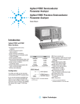
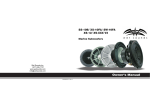
This is the html version of the file http://www.home.agilent.com/agilent/redirector.jspx?
action=ref&cname=AGILENT_EDITORIAL&ckey=590534&lc=eng&cc=US.
G o o g l e automatically generates html versions of documents as we crawl the web.
To link to or bookmark this page, use the following url: http://www.google.com/search?q=cache:rmXXR-sr_0J:www.home.agilent.com/agilent/redirector.jspx%3Faction%3Dref%26cname%3DAGILENT_EDITORIAL%26ckey%3D590534%26lc%3Deng%
26cc%3DUS+hp+41501b&hl=en&ct=clnk&cd=5&gl=us
Google is neither affiliated with the authors of this page nor responsible for its content.
These search terms have been highlighted: hp 41501b
Page 1
This literature was published years prior to the establishment of Agilent Technologies as a company independent from
Hewlett-Packard and describes products or services now available through Agilent. It may also refer to products/services no
longer supported by Agilent. We regret any inconvenience caused by obsolete information. For the latest information on
Agilent's test and measurement products go to:
www.agilent.com find products
Or in the US, call Agilent Technologies at 1-800-452-4844 (8am-8pm EST)
HP 4155B
Semiconductor Parameter Analyzer
HP 4156B
Precision Semiconductor Parameter Analyzer
Technical Data
Specifications - July 1997
Introduction
ì
Basic Functions
The HP 4155B and HP 4156B functions:
ì
Set measurement and/or stress
ì
conditions
ì
ì
ì
ì
ì
ì
SMU: Source Monitor Unit
HRSMU: High Resolution SMU
Perform measurement and analysis
with the built-in HP Instrument
BASIC
(1fA/2 V to 100mA/100V)
MPSMU: Medium Power SMU
Self test, Auto calibration
(10fA/2 V to 100mA/100V)
HPSMU: High Power SMU
Control measurement and/or stress
execution
Configuration
(10fA/2 V to 1A/200V)
VMU: Voltage Monitor Unit
VSU: Voltage Source Unit
PGU: Pulse Generator Unit (1 channel)
GNDU: Ground Unit
Perform arithmetic calculations
HP 4155B
Display measured and calculated
results on the LCD display
HP 4156B
4xMPSMU
2xVMU
2xVSU
Perform graphical analysis
Store and recall measurement setups,
and measurement and graphical display
data
4xHRSMU
2xVMU
2xVSU
*1: Minimum number of installable MPSMU
or PGU is two.
HP 41501B (Optional)
2xPGU(Option)
Dump to printers or plotters for hardcopy output
*1
HPSMU(Option) or
2xMPSMU (Option)
GNDU
*1
Page 2
2
Hardware
are specified at the rear panel connector
terminals when referenced to the Zero
Check terminal under the following
conditions:
Specification Condition
The supplemental information and
typical entries in the following specifications are not warranted, but provide
useful information about the functions
and performance of the instruments.
1. 23 C
5 C (double between 5 C to
18 C, and 28 C to 40 C if not noted
otherwise)
2. After 40 minutes warm-up
The measurement and output accuracy
3. Ambient temperature change less
than 1 C after auto calibration
execution.
4. Integration time: medium or long
5. Filter: ON (for SMUs)
6. Kelvin connection (for HRSMU,
HPSMU, and GNDU)
7. Calibration period: 1 year
HP 4156B Precision Semiconductor Parameter Analyzer
Voltage/Current Compliance
(Limiting):
HRSMU (High Resolution SMU) Specifications
Voltage Range, Resolution, and Accuracy (HRSMU)
Voltage
Range
2V
Set.
Reso.
V
Set.
Accuracy
V)
Meas.
Reso.
V
Meas.
Accuracy
V)
Max.
Current
100mA
The SMU can limit output voltage or
current to prevent damaging the device
under test.
Voltage: 0V to 100V
20V
1mV
mV)
V
1mV)
100mA
40V
2mV
±(0.025%+6mV)
V
2mV)
*1
40V
100V
2mV
5mV
V
V
±(0.025%+6mV)
mV)
2mV)
5mV)
*1: 100mA (Vout
[
20V), 50mA (20V Vout 40V)
*2: 100mA (Vout
[
20V), 50mA (20V Vout 40V), 20mA (40V Vout 100V)
*1
Current: 100fA to 100mA
Compliance Accuracy: Same as the
current (voltage) settling accuracy.
*2
HRSMU Supplemental Information:
Current Range, Resolution, and Accuracy (HRSMU)
Current
Range
±10pA
Set.
Reso.
10fA
Set.
Accuracy
±(4%+400fA)
±100pA
10fA
±1nA
100fA
±(4%+400fA)
±10nA
1pA
*1*2
*1*2
*2
±(0.5%+0.7pA+1fA Vout)
±(0.5%+4pA+10fA Vout)
Meas.
Reso.
1fA
Meas.
Accuracy
fA+1fA Vout/100)
1fA
fA+10fA Vout/100)
*1*2
*1*2
Max.
V
100V
100V
10fA
pA+1fA Vout)
10fA
pA+10fA Vout)
100V
pA+100fA Vout)
100V
*2
100V
±100nA
10pA
±(0.12%+40pA+100fA Vout)
100fA
±
100pA
±(0.12%+400pA+1pA Vout)
1pA
pA+1pA Vout)
100V
1nA
±(0.07%+4nA+10pA Vout)
10pA
nA+10pA Vout)
100V
10nA
±(0.07%+40nA+100pA Vout)
100pA
nA+100pA Vout)
100V
1nA
nA+1nA Vout)
100V
10nA
A+10nA Vout)
100V
100nA
A+100nA Vout)
±
A
A
±
A
± mA
± 0mA
m
100nA
A
±(0.06%+400nA+1nA Vout)
A+10nA Vout)
A
A+100nA Vout)
Maximum allowable cable resistance
when using Kelvin connection (Force,
Sense): 10
Typical voltage source output
resistance (Force line/non-Kelvin
connection): 0.2
Voltage measurement input resistance/
current source output resistance:
10 15 (10pA range)
Current compliance setting accuracy for
opposite polarity:
10pA to 10nA range: V/I setting
accuracy
*3
12% of range
100nA to 100mA range: V/I setting
*1: The accuracy is applicable when offset
cancellation has been performed.
*2: The offset current specification is
multiplied by one of the following factors
depending upon the ambient temperature
accuracy
Output terminal/connection:
Dual triaxial connectors, Kelvin
(remote sensing)
and humidity (RH = Relative Humidity):
Humidity %
RH
Temperature
5 - 60
60 - 80
100
Current (mA)
HRSMU Measurement and
5 C to 18 C
Output Range
18 C to 28 C
28 C to 40 C
*3: 100V (Iout
2.5% of range
[
20mA)
50
40V (20mA Iout 50mA)
20V (50mA Iout 100mA)
20
Vout is the output voltage in volts.
Iout is the output current in amps.
For example, accuracy specifications are
given as
-40
-100
-20
20
40
100
Voltage (V)
-20
of set/measured value (0.04%)
-50
plus offset value (200nA+1nA Vout) for the
1mA range. The offset value consists of a
fixed part determined by the set/measuremet
range and a proportional part that is
multiplied by Vout or Vout/100.
-100
Page 3
3
VSU (Voltage Source Unit)
Specifications
VMU (Voltage Monitor
Unit) Specifications
VSU Output Range:
VMU Measurement Range,
Resolution, and Accuracy:
Voltage
Range
20V
Meas.
Reso.
1mV
Meas.
Accuracy
(0.05% of setting+10mV)
*1: Specification is applicable under no load
current.
Max. Output Current: 100mA
VSU Supplemental Information:
*1
Voltage
Range
2V
Meas.
Reso.
2 V
Meas.
Accuracy
(0.02%+200 V)
20V
20 V
(0.02%+1mV)
VMU Differential Mode Range
For example, accuracy specifications are
given as
of set/measured value (0.02%)
plus offset value (1mV+13 V Vi) for the 2V
range. The differential mode offset value
consists of a fixed part determined by the
measurement range and a proportional part
that is multiplied by Vi.
VMU Supplemental Information:
Input Impedance: 1G
VSU Supplemental Information:
Output resistance: 0.2
Maximum load capacitance:
F
Maximum slew rate: 0.2V/ s
Current limit: 120mA (typical)
Output Noise: 1mV rms (typical)
VMU Differential Mode Range
Resolution, and Accuracy:
Diff V
Range
0.2V
Meas.
Reso.
1 V
Meas.
Accuracy
(0.03%+100 V+1.3 V Vi)
2V
2 V
(0.02%+1mV+13 V Vi)
Input leakage current (@0V): 500pA
(Typical)
Measurement noise: 0.01% of range
(p-p) (Typical)
Differential mode measurement noise:
0.005% of range (p-p) (Typical)
Max. Common Mode Voltage: 20V
Note: Vi is the input voltage of VMU2 in
volts.
HP 4155B Semiconductor Parameter Analyzer
Output terminal/connection:
MPSMU (Medium Power SMU) Specifications
Single triaxial connector, non-Kelvin
Voltage Range, Resolution, and Accuracy (MPSMU)
Voltage
Range
2V
20V
Set.
Reso.
V
Set.
Accuracy
V+0.3 Iout)
mV+0.3 Iout)
1mV
40V
2mV
100V
5mV
±(0.03%+7mV)+0.3 Iout)
mV)+0.3 Iout)
Meas.
Reso.
V
Meas.
Accuracy
V+0.3 Iout)
Max.
Current
100mA
(no remote sensing)
V
mV+0.3 Iout)
100mA
V
mV+0.3 Iout)
*1
mV+0.3 Iout)
*2
The SMU can limit output voltage or
current to prevent damaging the device
under test.
V
Voltage/Current Compliance
(Limiting):
*1: 100mA (Vout
[
20V), 50mA (20V Vout 40V)
Voltage: 0V to 100V
*2: 100mA (Vout
[
20V), 50mA (20V Vout 40V), 20mA (40V Vout 100V)
Current: 1pA to 100mA
Compliance Accuracy: Same as the
current (voltage) settling accuracy.
Current Range, Resolution, and Accuracy (MPSMU)
Current
Range
±1nA
Set.
Reso.
100fA
±10nA
1pA
±100nA
10pA
±
±
A
A
±
A
± mA
± 0mA
m
Set.
Accuracy
±(0.5%+3pA+2fA Vout)
Meas.
Reso.
10fA
Meas.
Accuracy
pA+2fA Vout)
Max.
V
100V
±(0.5%+7pA+20fA Vout)
10fA
pA+20fA Vout)
100V
±(0.12%+50pA+200fA Vout)
100fA
pA+200fA Vout)
100V
pA+2pA Vout)
100V
100pA ±(0.12%+400pA+2pA Vout)
1nA
±(0.12%+5nA+20pA Vout)
1pA
10pA
nA+20pA Vout)
100V
10nA
100pA
nA+200pA Vout)
100V
1nA
nA+2nA Vout)
100V
10nA
100nA
A+20nA Vout)
A+200nA Vout)
100V
±(0.12%+40nA+200pA Vout)
100nA ±(0.12%+500nA+2nA Vout)
A
A+20nA Vout)
A
A+200nA Vout)
*1: 100V (Iout
[
MPSMU Supplemental Information:
Typical voltage source output
resistance: 0.3
Voltage measurement input resistance/
current source output resistance:
10 13 (1nA range)
Current compliance setting accuracy for
opposite polarity:
1nA to 10nA range: V/I setting
*1
accuracy
20mA), 40V (20mA Iout 50mA), 20V (50mA Iout 100mA)
12% of range
100nA to 100mA range: V/I setting
accuracy
2.5% of range
Vout is the output voltage in volts.
Iout is the output current in amps.
For example, accuracy specifications are
given as
of set/measured value (0.1%)
plus offset value (30pA+200fA Vout) for the
100nA range. The offset value consists of a
fixed part determined by the set/measuremet
range and a proportional part that is
multiplied by Vout.
100
MPSMU Measurement and
Output Range
50
20
-100
VSU Specifications
Current (mA)
-40
-20
20
-20
40
100
Voltage (V)
Same as HP 4156B VSU.
-50
VMU Specifications
Same as HP 4156B VMU.
-100
Page 4
4
HP 41501B SMU and Pulse Generator Expander
Output terminal/connection:
HPSMU (High Power SMU) Specifications
Dual triaxial connectors, Kelvin (remote
Voltage Range, Resolution, and Accuracy (HPSMU)
Voltage
Range
2V
20V
Set.
Reso.
V
2mV
100V
5mV
200V
10mV
Current
Range
±1nA
Set.
Reso.
100fA
±10nA
1pA
±100nA
10pA
±
±
±
A
A
± mA
± 0mA
m
V)
Meas.
Reso.
V
Meas.
Accuracy
V)
Max.
Current
1A
sensing)
Voltage: 0V to 200V
mV)
V
2mV)
1A
±(0.03%+7mV)
mV)
V
3mV)
500mA
V
5mV)
125mA
V
10mV)
50mA
1mV
40V
A
Set.
Accuracy
mV)
Set.
Accuracy
Voltage/Current Compliance
(Limiting):
Current: 1pA to 1A
Compliance Accuracy: Same as the
current (voltage) settling accuracy.
±(0.5%+3pA+2fA Vout)
Meas.
Reso.
10fA
±(0.5%+7pA+20fA Vout)
10fA
pA+20fA Vout)
200V
±(0.12%+50pA+200fA Vout)
100fA
pA+200fA Vout)
200V
100pA
±(0.12%+400pA+2pA Vout)
1pA
pA+2pA Vout)
200V
1nA
10nA
±(0.12%+5nA+20pA Vout)
±(0.12%+40nA+200pA Vout)
10pA
100pA
nA+20pA Vout)
nA+200pA Vout)
200V
200V
100nA
A
±(0.12%+500nA+2nA Vout)
A+20nA Vout)
1nA
nA+2nA Vout)
200V
10nA
A+20nA Vout)
200V
100nA
A+200nA Vout)
*1
A+2 A Vout)
*2
A
A+200nA Vout)
A
A+2 A Vout)
1 A
Meas.
Accuracy
pA+2fA Vout)
Max.
V
200V
*1: 200V (Iout
[
50mA), 100V (50mA Iout 100mA)
*2: 200V (Iout
[
50mA), 100V (50mA Iout 125mA), 40V (125mA Iout 500mA),
HPSMU Supplemental Information:
Maximum allowable cable resistance
when using Kelvin connection:
Force: 0.7 (100mA to 1A)
Force: 10 ( 100mA)
Sense: 10
Typical voltage source output
resistance (Force line/non-Kelvin
connection): 0.2
Voltage measurement input resistance/
current source output resistance:
10 13 (1nA range)
Current compliance setting accuracy for
opposite polarity:
1nA to 10nA range: V/I setting
20V (500mA Iout 1mA)
accuracy 12% of range
100nA to 1A range: V/I setting
Vout is the output voltage in volts.
Iout is the output current in amps.
accuracy
For example, accuracy specifications are
given as
of set/measured value (0.1%)
plus offset value (30pA+200fA Vout) for the
100nA range. The offset value consists of a
fixed part determined by the set/measuremet
range and a proportional part that is
multiplied by Vout.
2.5% of range
Current (mA)
HPSMU Measurement
and Output Range
1000
500
PGU (Pulse Generator Unit)
Specifications
Modes: Pulse or constant
Amplitude: 0Vpp to 40Vpp
Window: -40.0V to +40.0V
Voltage (V)
125
50
-200
-100
-40
-20
20
40
100
200
-50
-125
Maximum current:
200mA (pulse width: 1ms, average
-500
current 100mA)
100mA
Pulse width: 1.0 s to 9.99s
Minimum resolution: 100ns
Pulse period: 2.0 s to 10.0s
Minimum resolution: 100ns
Delay: 0s to 10s
Minimum resolution: 100ns
Transition time: 100ns to 10ms
Minimum resolution: 1ns
Output impedance: 50 or low
impedance ( 1
Burst count range: 1 - 65535
-1000
Pulse/DC Output Voltage and Accuracy (PGU)
*1
Set
Voltage
Resolution
Parameter
Base
Range
20V
4mV
(1% of Base + 50mV +1% of Pulse)
40V
8mV
(1% of Base + 50mV +1% of Pulse)
20V
4mV
(3% of Base + 50mV)
40V
8mV
(3% of Base + 50mV)
Pulse
Note: DC output is performed by the Base parameter.
Accuracy
*1: Accuracy is specified at leading edge - trailing edge =
s
Page 5
5
Pulse parameter accuracy
Period: (2% +2ns)
Width: (3% +2ns)
Delay: (2% +40ns)
Pulse Range and Pulse Parameter (PGU)
Range
1
2
Period
Width
Delay
Set resolution
2 s - 100 s
1 s - 100 s
0 - 100 s
0.1
3
100 s - 1000 s
1ms - 10ms
1 s - 999 s
0.01ms -9.99ms
0 - 1000 s
0 - 10ms
4
5
10ms -100ms
100ms - 1000ms
0.1ms - 99.9ms
1ms - 999ms
0 - 100ms
0 - 1000ms
Transition time: (5% +10ns)
Trigger output
Level: TTL
Timing: Same timing and width as
PGU1 pulse output
6
1s - 10s
0.01s - 9.99s
0 - 10s
Note: Pulse width is defined when leading time is equal to trailing time. PGU2 must be set in
the same range as PGU1.
PGU Supplemental Information:
Leading/Trailing Edge Times (PGU)
Overshoot:
% of amplitude 10mV
(50 output impedance to 50 load)
Pulse width jitter: 0.2% + 100ps
Pulse period jitter: 0.2% + 100ps
Maximum slew rate: 100V/ s
(50 output impedance to 50 load)
Noise: 0.2% of range (@ DC output)
MPSMU Specifications
Same as HP 4155B MPSMU.
GNDU (Ground Unit)
Specifications:
Output Voltage: 0V 100 V
Maximum sink current: 1.6A
Output terminal/connection:
Single triaxial connector,
Kelvin (remote sensing)
Range
100ns - 1000ns
Set Restrictions
1ns
1 s
10
100
1ms
10ms
Accuracy
(5% + 10ns)
0.5 s - 10 s
10ns
(5% + 10ns)
5.0 s - 100.0 s
100ns
(5% + 10ns)
50 s - 1000 s
0.5ms - 10.0ms
1 s
(5% + 10ns)
10 s
(5% + 10ns)
Restrictions:
Pulse width < Pulse Period
Delay time < Pulse period
Leading time < Pulse width 0.8
Trailing time < (Pulse period - Pulse width) 0.8
Period, width, and delay of PGU1 and PGU2 must be in the same range. Leading time and
trailing time for a PGU must be in the same range.
GNDU Supplemental
Information:
Load Capacitance: 1 F
Cable resistance:
Force
1
Sense
1
Noise characteristics (typical,
Filter: ON):
Voltage source noise: 0.01% of V
range (rms)
Current source noise: 0.1% of I range
(rms)
Voltage monitor noise: 0.02% of V
range (p-p)
Current monitor noise: 0.2% of I
range (p-p)
Output overshoot (typical, Filter: ON):
Voltage source: 0.03% of V range
Current source: 1% of I range
Range switching transient noise
(typical, Filter: ON):
Voltage ranging: 250mV
Current ranging: 10mV
Measurement Set-up
Measurement
VAR1
Setting
The HP 4155B and HP 4156B can
perform dc or pulsed force/measure,
and stress force. For dc,
voltage/current sweep and sampling
HRSMU, MPSMU, and HPSMU
Supplemental Information:
Maximum capacitive load: 1000pF
Maximum guard capacitance: 900pF
Maximum shield capacitance: 5000pF
Maximum guard offset voltage: 1mV
Maximum slew rate: 0.2V/ s
Functions
ì
ì
Fill-in-the-blanks using front-panel or
full-size external keyboard
Primary sweep controls the staircase (dc
or pulsed) voltage or current sweep.
Maximum number of steps: 1001 for one
VAR1 sweep.
ì
ì
Load settings from floppy disk or via
the LAN port
Program using internal HP Instrument
BASIC or via HP-IB
ì
ì
ì
HELP Function
Library: Default measure setup, Vce-Ic,
Vds-Id, Vgs-Id, and Vf-If are predefined softkeys
User-defined measurement setup
library
ì
voltage/current sweep and sampling
(time domain) measurements are
available.
Voltage/Current Sweep
Measurement Characteristics
Each SMU and VSU can sweep using
VAR1 (primary sweep), VAR2
|
(subordinate sweep), or VAR1
(synchronous sweep).
VAR1 sweep.
Sweep type: linear or logarithmic
Sweep direction: Single or double sweep
Hold time:
Initial wait time or wait time after
VAR2 is set: 0 to 655.35s with 10ms
resolution
Delay time:
Wait time from VAR1 step to the start
of the measurement: 0 to 65.535s with
100 s resolution
Auto file load function on power-up
Page 6
6
Linear scale (no limit mode), log
scale, and thinned-out modes:
VAR2
Subordinate linear staircase or linear
pulsed sweep. After primary sweep is
completed, the VAR2 unit output is
incremented.
Maximum number of steps: 128
VAR1
|
Staircase or pulse sweep synchronized
with the VAR1 sweep. Sweep is made
with a user specified ratio and offset
|
value. VAR1
output is calculated as
VAR1
|
= a VAR1 + b, where a is the
user specified ratio and b is the user
specified offset value.
CONSTANT
A source unit can be set as a constant
voltage or current source depending on
the unit.
560 s (720 s at thinned-out mode)
to 1s range: 80 s resolution
1s to 65.535s range: 2ms resolution
Note: The following conditions must be set
when initial interval is less than 2ms.
ì
ì
ì
Number of measurement channels: 1
Measurement ranging: fixed range
Stop condition: disable
Hold time:
Initial wait rime: 0.03s to 655.35s,
100 s resolution
Sampling measurement stop condition:
A condition to stop the sampling can
be defined.
Sampling interval setting accuracy
(supplemental data):
0.5% + 10 s (sampling interval
480 s)
PULSE
One of the SMUs can be set as a pulse
source.
Pulse width: 0.5ms to 100ms, 100 s
resolution.
Pulse period:
(5ms to 1s ( pulse width + 4ms),
100 s resolution.
SMU pulse setting accuracy
(supplemental information, at fixed range
measurement except multi- channel
measurement):
Width: 0.5% + 50 s
Period: 0.5% + 100 s
Trigger output delay for pulsed
measurement: 0 - 32.7ms with 100 s
resolution (< pulse width).
0.5% + 10 s (480 s
interval <2ms)
0.5% + 100 s (2ms
interval)
sampling
sampling
Stress Force Characteristics
SMU, VSU, and PGU output can be
forced for the user specified period.
Stress time set range:
5000 s to 31,536,000s (365 days)
Resolution:
100 s (500 s stress time 10s)
10ms (10s<stress time 31,536,000s)
Burst pulse count:
1 - 65,535 (PGU only)
Trigger:
HP 4155B/4156B outputs a gate
Arithmetic and Analysis
Functions
Arithmetic Functions
User Functions
Up to six USER FUNCTIONS can be
defined using arithmetic expressions.
Measured data and analyzed variables
from graphics analysis (marker, cursor,
and line data) can be used in the
computation. The results can be
displayed on the LCD.
Arithmetic Operators
+, -, *, /, ^, LGT (logarithm, base 10),
LOG (logarithm, base e), EXP
(exponent), DELTA, DIFF (differential),
INTEG (integration), MAVG (moving
average), SQRT, ABS (absolute value),
MAX, MIN, AVG (averaging), COND
(conditional evaluation).
Physical Constants
Keyboard constants are stored in memory
as follows:
q: Electron Charge, 1.602177 E-19 C
k: Boltzman s Constant, 1.380658 E-23
Dielectric Constant of Vacuum,
8.854188 E-12
Engineering Units
The following unit symbols are also
available on the keyboard: f (10
), n (10
-9
K (10 ), M (10
6
p (10
-12
3
), u or (10
9
), G (10 )
Analysis Capabilities
-6
-15
),
), m (10
resolution (< pulse width).
Sampling (Time Domain)
Measurement Characteristics
Displays the time sampled voltage/
current data versus time.
Maximum sampling points: 10,001
(linear)
Sampling mode: linear, log, and
thinned-out
Note: The thinned-out mode is similar to
reverse-log sampling. Sampling
measurement continues by thinning out
older data until the sampling completion
condition is satisfied.
Sampling interval range and resolution:
Linear scale (auto mode):
60 s to 480 s range: 20 s resolution
480 s to 1s range: 80 s resolution
1s to 65.535s range: 2ms resolution
HP 4155B/4156B outputs a gate
trigger while stress channels are
forcing stress.
Knob Sweep
In the knob sweep mode, sweep range
is controlled instantaneously with the
front-panel rotary knob.
Only the Channel Definition page needs
to be defined.
Standby Mode
SMUs in Standby remain
programmed to their specified output
value even as other units are reset for
the next measurement.
Analysis Capabilities
Overlay Graph Comparison
A graphics plot can be stored and later
recalled as an overlay plane. Four
overlay planes can be stored. One plane
can be overlaid onto the current data.
Marker
Marker to min/max, interpolation, direct
marker, and marker slip
Cursor
Long and short, direct cursor.
Line
Two lines, normal mode, grad mode,
tangent mode, and regression mode.
Other Characteristics
Limited auto-ranging, voltage/current
compliance, power compliance,
automatic sweep abort functions,
self-test, and self-calibration.
Scaling
Auto scale and zoom.
Page 7
7
Data Variable Display
Up to two user defined parameters can be
displayed on the graphics screen.
Read Out Function
The read out functions are built-in
functions for reading various values
related to the marker, cursor, or line.
Automatic Analysis Function
On a graphics plot, the markers and lines
can be automatically located using the
auto analysis setup. Parameters can be
automatically determined using
automatic analysis, user function, and
read out functions.
User Variable
Display the data on the LCD via HP-IB
or HP Instrument BASIC.
Output
Display
Display Modes
Graphics and list.
Text Hard Copy
Print out setup information or measured
data list as ASCII text via HP-IB,
parallel printer port, or network
interface to supported HP plotters or
printers. PCL, HR PCL, and HP GL
formats are supported (selectable).
Hard Copy File
Hard copy output can be stored to an
internal or external mass storage device
instead of sending it to a printer or
plotter. The data can be stored in PCL,
HR PCL, TIFF, HR TIFF (highresolution TIFF), or HP GL formats.
Hard Copy via Network Interface
The network interface has lpr client
Maximum number of files allowed per
directory on network mass storage
device: 199
Data storage (supplemental data):
2HD DOS format:
Available bytes: 1457K (byte)
File size:
Measurement setup: 3843 (byte)
Stress setup: 601 (byte)
Measurement setup/result
(Typical data): 15387 (byte)
(VAR1: 101, VAR2: 5)
Customized system setup: 1661 (byte)
Hardcopy data: 30317 (byte)
(Monochrome PCL 75DPI file)
Hardcopy data: 38702 (byte)
(monochrome TIFF file)
Note: For LIF format, the total number of files
capability.
is limited to 199.
High-Resolution (HR) Mode
This file mode is available for cases
where an extremely clean print-out or
plot is desired.
Repeating and Automating Test
Note: High resolution mode takes significantly greater CPU time to generate, so its
use is recommended for final reports only.
Instrument Control
HP 4155B and 4156B function control:
Internal or external computer controls
the HP 4155B and HP 4156B functions
Graphics Display
X-Y or X-Y1/Y2 plot of source
current/voltage, measured
current/voltage, time, or calculated
USER FUNCTION data.
List Display
Measurement data and calculated USER
FUNCTION data are listed in
conjunction with VAR1 step number or
time domain sampling step number. Up
to eight data sets can be displayed.
Display
8.4 inch diagonal color active matrix
LCD, 640 dot (H) 480 dot (V)
Hard Copy Functions
Graphics Hard Copy
Measured data and all data appearing on
the LCD can be output via HP-IB,
parallel printer port, or network interface
to supported HP plotters or printers.
PCL, HR PCL (high-resolution PCL),
and HP GL formats are supported
(selectable).
Data Storage
Mass storage device:
Built-in 3.5 inch flexible disk drive
Media: 3.5 inch 2HD or 2DD diskette
Format type: HP LIF and DOS
User area:
1.44Mbyte (2HD) or 720Kbyte (2DD)
File types:
Auto start program file, initial setup
file, measurement setup file,
measurement setup/result file, stress
setup file, customize file, hard copy
data file, and HP Instrument BASIC
program and data file.
Format of data made by HP BASIC
program:
Data made by HP BASIC program and
data made by HP Instrument BASIC
program are compatible.
Network mass storage device:
An NFS mountable mass storage
device
File types:
Auto start program file, initial setup
file, measurement setup file,
measurement setup/result file, stress
setup file, customize file, and hard
copy data file.
the HP 4155B and HP 4156B functions
via HP-IB interface.
Command sets:
SCPI command set
HP FLEX command set
HP 4145B command set
Program Memory:
Using the HP 4155B/4156B HP FLEX
command set, the user can store
program code in the HP 4155B or the
HP 4156B. Maximum number of
subprograms is 256 (8 bit).
External instrument remote control:
Control external equipment via HP-IB
interface.
Page 8
8
HP Instrument BASIC
HP Instrument BASIC is a subset of
HP BASIC.
Functions:
Arithmetic operation, binary operation,
string manipulation, logical operation,
array operation, program flow control,
event-initiated branching, program
editing and debugging support, mass
storage operation, instrument control,
real-time clock, softkey operation, and
graphics.
HP 4145B automatic sequence program
(ASP) typing aid:
HP 4145B ASP-like syntax softkeys are
available in HP Instrument BASIC. An
HP 4145B ASP file cannot be read by
HP-IB program
HP-IB programs for the HP 4145B can
be used when the HP 4145B command
set is selected.
Note: There is a possibility that HP-IB
programs for the HP 4145B will need to be
modified.
Interfaces
HP-IB interface:
SH1, AH1, T6, L4, SR1, RL1, PP0,
DC1, DT1, C1, C2, C3, C4, C11, E2
Parallel interface: Centronics
RJ45:
Ethernet IEEE 802.3 10BASE-T for a
10Mbps CSMA/CD local area
network
General Specifications
Temperature range
Operating:
+10 C to +40 C (if using floppy disk
drive)
+5 C to +40 C (if not using floppy
disk drive)
Storage: -22 C to +60 C
Humidity range
Operating:
20% to 80% RH, non-condensing and
wet bulb temperature 29 C (if using
floppy disk drive)
15% to 80% RH, non-condensing and
wet bulb temperature
29 C (if not
HP 4145B ASP file cannot be read by
the HP 4155B and 4156B.
Remote control:
HP Instrument BASIC is remote
controllable from an external computer
via the HP-IB interface.
HP Instrument BASIC memory area
(supplemental data):
Program (text) area: 16K (byte)
Variable/stack area: 500K (byte)
Common variable area: 600K (byte)
Note: The memory size for common variable
is decreased when hard copy or disk operation
is performed.
Trigger
Input:
External trigger input starts a sweep or
sampling measurement or can be used
as a trigger input for continuing an
HP Instrument BASIC program.
Input Level:
TTL level, negative or positive edge
trigger
Output:
External trigger can be generated by the
following events: start of each sweep
measurement step, start of each pulse
(SMU) output, while the stress source
is forcing, and Instrument BASIC
trigger out command execution.
Output Level:
TTL level, negative or positive logic
HP 4145B Data Compatibility and HP 4145B
Syntax Commands
Setup and data file
Measurement setup and data from the
HP 4145B can be loaded.
network
External keyboard:
Compatible PC-style 101-key
keyboard (mini DIN connector)
Interlock and LED connector
R-BOX control connector
Trigger in/out
SMU/PGU selector control connector
(HP 41501B)
wet bulb temperature 29 C (if not
using floppy disk drive)
Storage: 5% to 90% RH , noncondensing and wet bulb temperature
39 C
Altitude
Operating: 0 to 2,000 m (6,561 ft)
Storage: 0 to 4,600 m (15,091 ft)
Power requirement
90V to 264V, 47 to 63 Hz
Sample Application
Programs
Maximum VA
HP 4155B or 4156B: 450VA
HP 41501B: 350 VA
Flash EEPROM test
TDDB
Constant I (Electromigration test)
V-Ramp Test
J-Ramp Test
SWEAT
GO/NO-GO Test
HCI degradation test
Regulatory Compliance
EMC:
EN55011 (1991) Group 1, Class A,
EN50082-1 (1992)
Safety:
CSA C22.2 NO. 1010.1 (1992)
IEC 1010-1 (1990) + A2/EN61010-1
(1993)
Sample VEE Program
Vth measurement using the HP 4155B
or HP 4156B, the E5250A, and a wafer
prober.
VXIplug&play Drivers
VXIplug&play drivers for the
HP 4155B and HP 4156B
Supported VXIplug&play operating
systems:
Windows NT
Windows 95
Format
Tree-structured function panel.
Panel mode for hardware configuration and manual parameter setting.
Parameter mode for variable definition
and I/O configuration.
Dimensions:
HP 4155B and 4156B:
235mm H 426mm W 600mm D
HP 41501B:
190mm H 426mm W 600mm D
Weight (approx.):
HP 4155B and 4156B: 21kg
HP 41501B: 16kg
(option 412, HPSMU + 2 PGU)
HP 4155B and HP 4156B
Furnished Accessories
Triaxial cable, 4 ea. (HP 4155B)
Kelvin triaxial cable, 4 ea. (HP 4156B)
Coaxial cable, 4 ea.
Interlock cable, 1 ea.
Keyboard, 1 ea.
User manual, 1 set
Sample application program disk, 1 ea.
Sample VEE program disk, 1 ea
VXIplug&play drivers disk for the
HP 4155B & HP 4156B, 1 ea.
VXIplug&play drivers disk for the
HP E5250A, 1 ea
Page 9
9
Accessory Specifications
Specification Condition
The supplemental information and typical
PGU port signal transfer characteristics
HP 16442A Test Fixture
entries in the following specifications are not
warranted, but provide useful information
about the functions and performance of the
instruments. 23 C
5 C, 50% RH.
teristics
Overshoot: < 5% of pulse amplitude
(@20ns leading and trailing time, 50
pulse generator source impedance,
50pF and 1M in parallel load).
HP 16440A
SMU/Pulse Generator
Selector
The HP 16440A switches either an SMU
or PGU to the associated output port.
You can expand to 4 channels by adding
an additional HP 16440A. The channel 1
PGU port provides PGU OPEN
function, which can disconnect the PGU
by opening a semiconductor relay. The
HP 16440A cannot work without two
pulse generator units of the
HP 41501A/B (SMU and Pulse
Generator Expander).
Channel configurations:
Two channels (CH1, CH2)
CH1: INPUT ports: 2
(SMU and PGU, PGU port has
additional series semiconductor relay)
OUTPUT port: 1
CH2: INPUT ports: 2 (SMU and PGU)
OUTPUT port: 1
Voltage & Current Range
Input port
SMU
Max. V
200 V
Max I
1.0 A
PGU
40V
0.2A (AC peak)
Supplemental Information (at
23 C 5 C, 50% RH)
SMU port leakage current:
< 100fA @100V
SMU port residual resistance (typical):
0.2
SMU port stray capacitance (typical
@1MHz):
General Specifications
Dimensions:
50 mm H 250 mm W 275 mm D
Weight (approx.): 1.1kg
HP 16441A R-BOX
HP 16441A R-BOX adds a selectable
series resistor to the SMU output. You
can select the resistor from the setup
page, and the voltage drop due to the
series resistor is automatically
compensated for in the measurement
result.
Measurement limitations with the HP
4155B/56B and R-BOX:
ì
If you measure device characteristics
including negative resistance over
1M with the HP 4155B/56B and
R-BOX, there is a possibility that
they cannot be measured.
ì
There is a possibility that the
HP 4155B/56B cannot perform
measurements because of DUT
oscillations even with the R-BOX.
Whether oscillation occurs or not
depends upon the DUT and
measurement conditions.
Number of SMU channels that can add
resistor: 2
Resistor values:
1M , 100k , 10k , 0 (each
channel)
Resistance accuracy:
Channel Information
SMU:
6 channels (1 triaxial connector/
channel)
3 channels (1 Kelvin triaxial connector/
channel)
VSU:
2 channels (1 BNC connector/channel)
VMU:
2 channels (1 BNC connector/channel)
PGU:
2 channels (1 BNC connector/channel)
GNDU:
1 channel (1 triaxial connector)
INTLK: 6 pin connector
Supplemental Information (at
23 C 5 C, 50% RH)
SMU channel:
Leakage current: 10pA max @200V
(Force or Sense Common)
Stray capacitance: 15pF max
(Force or Sense Common)
Stray capacitance: 3pF typical
(Force or Sense Other SMU)
Residual resistance: 60m typical
(Force, Sense)
Guard capacitance: 70pF max
(Force or Sense Guard)
VSU channel residual resistance:
60m typical
VMU channel residual resistance:
60m typical
PGU channel characteristic impedance:
50 typical
GNDU channel residual resistance:
40m typical (Force, Sense)
0.3% (at 23 C 5 C, between inputoutput terminal)
Maximum voltage: 200V
General Specifications
Temperature range
Force Guard: 15pF
Maximum current: 1A (0 selected)
Kelvin connection: Kelvin connection
Guard Common: 130pF
is effective only when 0 is selected.
Storage: -40 C to +70 C
Humidity range
Operating: 5% to 80% RH
(no condensation)
Force Common: 0.3pF
PGU port residual resistance: 3.4
PGU port OFF capacitance (typical):
5pF
PGU port OPEN capacitance (typical):
700pF (@ 1MHz, Vin - Vout = 0V)
Supplemental Information (at
23 C 5 C, 50% RH)
Leakage current: <100fA @ 100V
General Specifications
Dimensions:
Operating: +5 C to +40 C
Storage: 5% to 90% RH at 65 C
(no condensation)
Dimensions:
140 mm H 260 mm W 260 mm D
Weight (approx.): 2.5kg
72 mm H 250 mm W 270 mm D
Weight (approx.): 1.6kg
Page 10
Page 10
10
For more information on Hewlett-Packard
Test & Measurement products, applications,
services, and current sales office listings, visit
our web site at http://www.hp.com/go/tmdir.
You can also contact one of the following
centers and ask for a test and measurement
sales representative.
Semiconductor Test Web Site:
http://www.hp.com/go/semiconductor
United States:
Hewlett-Packard Company
Test and Measurement Call Center
P.O. Box 4026
Englewood, CO 80155-4026
1-800-452-4844
Canada:
Hewlett-Packard Canada Ltd.
5150 Spectrum Way
Mississauga, Ontario
L4W 5G1
905-206-4725
Europe:
Hewlett-Packard
European Marketing Centre
P.O. Box 999
1180 AZ Amstelveen
The Netherlands
(31-20) 547-9900
Japan:
Hewlett-Packard Japan Ltd.
Measurement Assistance Center
9-1, Takakura-Cho, Hachioji-Shi,
Tokyo 192, Japan
Tel: (81) 426-56-7832
Fax: (81) 426-56-7840
Latin America:
Hewlett-Packard
Latin American Region Headquarters
5200 Blue Lagoon Drive
9th Floor
Miami, Florida 33126 USA.
305-267-4245/4220
Australia/New Zealand:
Hewlett-Packard Australia Ltd.
31-41 Joseph Street
Blackburn, Victoria 3130
Australia
1-800-629-485
Asia Pacific:
Tel: (852) 2599-7777
Fax: (852) 2506-9285
Taiwan:
(886-2) 717-9524
Korea:
(822) 769-0800
Singapore:
Singapore:
(65) 1800-292-8100
©Hewlett-Packard Company 1997
Data subject to change
Printed in USA. 7/97
5965-9619E