1
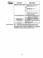
Previous Menu
FAI 1OC SECURITY
This
security
k\\
N5672-1 V2
12/95
system
6 EOLR
SYSTEM
can support
wired zones
PROFESSlONAL
SECURITY SYSTEMS
CONGRATULATIONS!
On Your Purchase
The purpose of these Installation Instructions
instructions for installing a basic system.
of the FM 1OC
is to give you a complete overview of the system, and provide
CONTACTLNG TECHNICAL
SUPPORT
PLEASE,
Before you call Technical Support, be sure your
l
l
l
l
l
l
READ THE INSTRUCTIONS!
Check all wiring connections.
Determine that the power supply and/or backup battery are supplying proper voltages
Verify your programming information where applicable.
Note the proper model number of this product, and the version level (if known) along with any
documentation that came with the product
Note your customer number and/or company name.
Having this information
handy will make it easier for us to serve you quickly and effectively.
You may contact Technical Support via Toll Free Fax. Please include your return Fax number. You will
receive a reply within 24 hours. You may also contact Technical Support via modem to ATLIS-BBS, Tech
Supports Electronic Bulletin Board System. Replies are posted within 24 hours.
Premier
Gold ‘Technical Support:
l-800-538-5585
(8 a.m.-6 p.m. E.S.T.)
After 6p.m. E.S.T.: l-800-421-5557
Please be sure you have your PIN number ready before calling.
Technical
ATLIS-BBS
Support Fax Number:
Electronic
Bulletin
l-800-447-5086
Board System: l-51 6-496-3980
(1200 - 9600 Baud, 8 Data Bits, 1 Start/Stop Bit, No Parity)
I
FOR YOUR CONVENIENCE,
two easily removable Programming Forms
have been included at the center of this manual.
-2-
I
INFORMATION..
Section
1. GENERAL
..........
Introduction ......................................................
.........................................
Zone Characteristics..
CONFIGURATIONS..
Section
2. SYSTEM
.......
ZONE RESPONSE TYPE DEFINITIONS.. ...................
HARD WIRED ZONES.. ...........................................
Basic Control’s Zones .........................................
3. MOUNTING
THE CONTROL,
.................
LOCK, & PC BOARD
..........................................
Mounting the Cabinet
Installing the Lock (if Used). .................................
Installing the Control’s Circuit Board.. .....................
.I3
Power Failure.. .................................................
.13
Other Displays (Fixed Word Keypads) ..................
Section
6. PROGRAMMING
THE SYSTEM .... ..l 4
.14
General Information .........................................
Summary of Programming Commands.. .................. 15
.15
Special Messages.. ..........................................
.16
DATA FIELDS.. ............................
PROGRAMMING
........
.2
0
Section
7. SYSTEM
COMMUNICATION
.20
Report Code Formats ........................................
.5
5
5
.
6
7
7
Section
4. WIRING
& POWERING
THE SYSTEM .........................
Grounding
the System.. .......................................
Terminals and Connections .................................
Power-up Procedure .........................................
8
8
8
8
Section
8. REMOTE
PROGRAMMING
AND
.....
(DOWNLOADING).
CONTROL
General information.. ........................................
Required.. ........................................
Equipment
.2 1
.21
.21
.21
Programming.. .................................................
Remote Programming Advisory Notes.. ................. .22
.23
Section
9. TESTING
THE SYSTEM .............
.23
Procedure.. .....................................................
Section
10. SPECIFICATIONS
&
.25
ACCESSORIES..
..................
.25
SPECIFICATIONS.. .............................................
.26
..............
ACCESSORIES (COMPATIBLE DEVICES).
28
.................................
FCC STATEMENTS
Section
OPERATION..
Section
5. SYSTEM
.............
SECURITY CODES ..............................................
Master Code.. ..................................................
User Codes ......................................................
KEYPAD FUNCTIONS ..........................................
General Information ...........................................
Arming Functions ..............................................
Keyswitch Operation (if installed) ........................
Panic Keys ......................................................
TROUBLE CONDITIONS .......................................
General Information ..........................................
“Check’ and “Battery” Displays ...........................
.9
9
.9
.I 0
.l 1
.l 1
.l 1
11
.I 1
11
12
...................
CANADIAN
DOC STATEMENT
LIMITATIONS
OF THIS ALARM
SYSTEM
.............................
LIMITED
WARRANTY
.12
12
Diaarams
.13
.13
.13
and
......
.2 9
.30
.3 1
Tables
.24
GUIDE.. ..................
TROUBLESHOOTING
SUMMARY
OF CONNECTIONS
DIAGRAM.......2
7
.Centerfold
FORM .................
PROGRAMMING
-3-
-4-
Introduction
Alarm
Output
Advisory
System
The FAl 1OC is a microprocessor-based
security control.
Zones Supported
Supports up to 6 hard wired EOLR “basic” zones.
Refer to the Zone Characteristics chart below for detailed
zone information.
Programming
The system can be easily programmed from any of the
remote consoles listed below.
Programmed options to establish specific alarm and reporting features are stored in electrically erasable, nonvolatile EEROM memory. This means that the unit can be
reprogrammed many times (unlike units equipped with
PROMS) and that information
which has been programmed will not be lost in the event of a complete loss of
power.
In addition, the system can be uploaded, downloaded, or
controlled via a computer and Hayes modem (see REMOTE PROGRAMMING AND CONTROL on page 21).
Remote Consoles
The system may use one or more FA200KP, FA210KP,
FA250KP, FA310KP, or Ademco 5330 Keypads. The first
four have digital keypads and fixed English status LCDs.
The 5330 provides programmable English language zone
descriptors and status indications (select for Vector device, as described in the 5330’s installation instructions).
Note:
FA210KP,
FA250KP,
and FA310KP
are
addressable keypads and must be set to their
non-addressable mode fdevice ID 31).
The system may also be armed and disarmed using a
keyswitch (Ademco No. 4116).
User Codes
Up to 3 secondary user codes can be assigned by the system’s Master code.
Communication
The system provides communication
capability (central
station reporting, etc.) over existing telephone lines.
Zones
Wired
Programmable
Zones.
EOLR supervised,
N.O. or N.C. sensors, 300-500 msec normal response.
Optional fast (1 O-l 5msec) response programmable
for
zone 3.
This system includes an alarm
output
rated
at 2 amps.
Throughout
the
manual,
wherever
reference
is
made
to
Alarm
Output
Ratings,
they
assume
a
fully
charged
battery
is
connected,
unless
the UL
rating is stated. The battery
is periodically
tested automatically (approximately
every four
hours), and if it cannot sustain a
load, a low battery message is
displayed and can be reported to
the central station.
Multiple
Consoles
(up to 4...see page 9) may be
used, as long as their total current drain is within the alarm and
auxiliary power output limitations
described in the SPECIFICATIONS AND ACCESSORIES
section.
Zone
Characteristics
1-6
For more information,
see page 7.
Zones
7, 95, 96
For more information,
see page 14.
state-of-the-an
Keypad
Panics. 24hr zones. Zone 7 is programmable
for silent, audible, auxiliary, or fire. Zones 95 (Silent Panic)
and 96 (Audible Panic) are fixed-function zones.
Duress (see User’s Manual).
Tamper. Reports faults in the trouble-by-day/alarm-bynight zones and (when used) the arming/disarming
keyswitch. For all report formats (except Contact ID, which
provides more explicit reporting)
a trouble code is
reported when the system is not armed, and Zone 9 report
code is sent for an alarm.
-5-
ZONE
RESPONSE
General
Information
TYPE DEFINITIONS
Each zone must be assigned to a zone type, which defines the way in which the
system responds to faults in that zone. Zone types are defined below.
Zone l@e 2 is not used in this svstem.
Program a zone with this zone type if the zone is not used.
Zone Disabled
(or Undefined)
This zone type provides entry delay whenever the zone is faulted if the
armed in the Away or Stay modes. When the panel is armed in the
Maximum modes, no entry delay is provided. Exit delay begins whenever
trol is armed, regardless of the arming mode selected. These delays
grammable. This zone tyoe is usually assianed to sensors or contacts
throuah which orimarv entrv and exit will take olace.
piiiq
Entry/ExitBurglary
/Tiizq
control is
Instant or
the conare proon doors
This zone type gives an instant alarm if the zone is faulted when the panel is
armed in the Away, Stay, Instant or Maximum modes. This zone tvoe is usually assianed to all sensors or contacts on windows and seldom used exterior doors.
Perimeter
Burglary
Interior,
piiiq
Follower
This zone type is active when the panel is armed in the Away or Maximum modes.
Entry delay (using the programmed entry time) results if the panel is armed in the
Away mode and the entry/exit zone is faulted first. Otherwise this zone type gives
an instant alarm. Exit delay is present for any arming mode. This zone tvoe is
usuallv assianed to a zone coverina an area such as a fover. lobbv. or hallway
throuah which one must oass (upon entrv. after faultina the entrv/exit zone) to
reach the kevoad to disarm the svstem. Since this zone type is designed to provide an instant alarm if the entry/exit zone is not violated first, it will protect an area
in the event an intruder hides on the premises prior to the system being armed, or
gains access to the premises through an unprotected area. This zone type is
bypassed
automatically
when the panel is armed Stay or Instant.
(Type
This zone type will give an instant alarm if faulted when armed in the Away, Stay,
Instant or Maximum (night) modes. During the disarmed state (day), the system
will provide a latched trouble sounding from the keypad (and a central station report, if desired). This zone type is usuallv assianed to a zone which contains a foilprotected door or window (such as in a store). or to a zone coverina a “sensitive”
area such as a stock room. drua SUDDIV room. etc. This type can also be used on a
sensor or contact in an area where immediate notification of an entry is desired.
Trouble
Alarm
by Day/
by Night
(
24-hour
24-hour
Silent
Alarm
1 Type 71
Audible
Alarm
m
Auxiliary
24-hour
Alarm
[Type
Supervised
Fire
lType[
Interior
w/Delay
This zone type sends a report to the Central Station but provides no keypad display or sounding. This zone tvoe is usuallv assianed to a zone containing an
Emergency button.
This zone type sends a report to the Central Station, and provides a rapid beeping sound at the keypad, and an audible external alarm. This zone tvoe is usually
assianed to a zone that has an Emeraencv button.
This zone type sends a report to Central Station and provides a rapid beeping
sound at the keypad. (No bell output is provided).
Usually assigned to a
zone containing a button for use in personal emergencies, or to a zone Containing monitoring devices such as water or temperature sensors, etc.
This zone type provides a fire alarm on short circuit and a trouble condition On
open circuit. The bell output will pulse when this zone type is faulted. This zone
type is always active and cannot be bypassed. This zone type can be assigned
on/v to control oanel wired zone 5. or kevoad manic zone 7.
This zone type gives entry delay (using the programmed entry time), if tripped
when the panel is armed in the Away mode, regardless of whether or not an entry/exit delay zone was tripped first. This zone type is also active during Maximum
mode, but no entry delay is provided (an alarm occurs immediately if the zone is
tripped). Exit delay is present for any arming mode. This zone type is bypassed automatically
when the panel is armed Stay or Instant.
-6-
HARD-WIRED
Basic
Control%
ZONES
Zones
The FAl 1OC supports 6 hard-wired zones, which are connected as zones l-6 .
These zones must be EOLH supervised, and can use N.O. and/or N.C. sensors.
Zone
Response
Response
Type
Time
Max. Zone Resistance
EOLR
Supervised
Any zone response can be assigned to devices on
these zones except Supervised Fire (09), which
can be assigned only to zone 5 (see below).
300500 msec. Zone 3 is optionally programmable
for fast (1 O-l 5msec) response.
300 ohms, excludina EOLR
Supports both open circuit and closed circuit
devices.
Connect open circuit devices in parallel across
the loop. The 1,000 ohm EOLR must be
connected across the loop wires at the last
device.
Important
If the EOLR is not at the end of the
loop, the zone is not properly supervised. The
system may not respond to an open circuit within
the zone.
Connect closed circuit devices in series with the
loop.
Of the 6 hard wired zones, only zone 5 can be
used for fire.
Supports as many 4-wire smoke detectors as can
be powered.
The zone must be configured
for EOLR
supervision.
The detectors must be wired in parallel, with the
EOLR at the last detector for full supervision.
To supervise power, a supervisory module (e.g.,
System Sensor A77-7168 EOL Relay Module) is
required.
l
l
l
EOLR
Fire
Zone
5
l
l
f
l
l
l
-7-
1
Mounting
the
Installing
Installing
Cabinet
the Lock
(if Used)
the Control’s
Circuit
Board
IMPORTANT!
the
installing
Before
contents,
be
cabinet’s
sure to remove
the appropriate
metal
cabinet
knockouts.
The FAl 1OC is supplied with a 12-l/2” (318mm) wide x 14-l 12” (368mm) high x
3” (76mm) deep cabinet suitable for use in most installations.
Mount the control cabinet to a sturdy wall using fasteners or anchors (not
supplied) in a clean, dry area which is not readily accessible to the general public.
4 mounting holes are provided at the back of the cabinet.
Use an Ademco No. N6277 Cam
Lock and No. N6277-1 Push-On Clip
(Retainer Clip).
1. Remove the cabinet cover. If is
easily removable for servicing
and is easily reinstalled.
2. Remove the lock knockout from
the control cabinet cover. Insert
the key into the lock. Position
the lock in the hole making certain that the latch will make contact with the latch bracket when
the door is closed.
3.
While holding the lock steady,
insert the retainer clip into the
retainer slots. Position clip as illustrated to facilitate easy removal.
1.
Hang two long mounting clips (provided) on the raised cabinet tabs (see Detail B below).
Insert the top of the circuit board into the slots at the top of the cabinet. Make
sure that the board rests on the correct row (see Detail A ).
Swing the base of the board into the mounting clips and secure the board to
the cabinet with the accompanying screws (see Detail B).
2.
3.
DO NOT ATTEMPT TO REMOVE THE KNOCKOUTS AFTER THE CIRCUIT BOARD HAS
BEEN INSTALLED.
-8-
(See Summary
IMPORTANT:
Grounding
the
System
Terminals
and
Connections
of Connections
Diagram
on Page
27)
Do not connect
the battery,
or plug in the AC transformer,
until all other wiring connections
have been completed.
Terminal 21 is the earth ground connection point. In order for the protective
devices in this product to be effective, the designated
terminal must be
terminated in a good earth ground. The following are examples of good earth
grounds available at most installations:
Metal cold water pipe: Use a non-corrosive metal strap firmly secured to the
pipe to which the lead is electrically connected and secured.
AC power outlet ground:
Available from 3-prong, 120 VAC power outlets
only. To test the integrity of the ground terminal, use a 3-wire circuit tester with
neon lamp indicators, such as the UL Listed Ideal Model 61-035, or equivalent,
available at most electrical supply stores.
1 & 2:
AC Input (16SVAC, 25VA) from No. 13211TF2 plug-in transformer
(in U.S.A.).
Note: In Canadian installations, a No. 1321 CN transformer must be used.
Alarm relay output(+), 12VDC, 2.OA maximum
3:
(600mA max Alarm plus Aux Power for UL usage).
4:
Ground (-) Return for Alarm Output Auxiliary Power and Wired Fire.
Via their BLACK leads for Keypad(s)t and optional Keyswitch.
+12VDC Output (at 500mA max.) for Auxiliary Power and Wired Fire.
5:
Via their RED leads for Keypad(s)t and optional Keyswitch.
Data In from Keypad(s)* and optional Keyswitch, via their GREEN leads.
6:
Data Out to Keypad(s)t and optional Keyswitch, via their YELLOW leads.
7:
Zone 1. Note:
For each zone used, a 1,000 Ohm EOLR should be wired
8:
between the farthest sensor connected to the zone
terminal and the low side of the zone.
Zones 1 and 2 Return.
9:
10: Zone 2 (see Note at zone 1)
11: Zone 3 (see Note at zone 1)
12: Zones 3 and 4 Return
13: Zone 4 (see Note at zone 1)
14: Zone 5 (see Note at zone 1)
15: Zones 5 and 6 Return.
16: Zone 6 (see Note at zone 1)
Handset (TIP).
17:
Handset (RING).
18:
Incoming Phone Line (TIP).
19:
Incoming Phone Line (RING).
20:
EARTH GROUND (a proper earth ground must be provided to protect the
21:
system from lightning and electrostatic discharge damage).
Warning:
To prevent the risk of electrical shock, disconnect the telephone line
at the Telco jack before servicing the unit.
Battery (+). When AC is present, 13.8VDC is being developed to
RED LEAD:
recharge a gel lead acid battery and when AC is absent, 12VDC current is
drawn from the battery. Battery lead reversal will blow the battery fuse.
BLACK
LEAD:
Battery (-).
t
Up to 4 Keypads may be used (check total auxiliary current, per SPECIFYCATIONS). Each 5330 Keypad used must be on an individual home run.
No more than 220’ of #22 wire or 550’ of #18 wire should be used for each
run.
Addressable Keypads (e.g., FA310KP, FA250KP) may be used, if they are
set to their non-addressable mode (device ID 31).
-9-
Power-up
Procedure
1.
2.
3.
4.
5.
Make sure that the total current to be drawn from the Alarm Output terminals
(3 & 4) and Auxiliary Power Output terminals (4 & 5) does not exceed the
values indicated in the SPECIFICATIONS section and on the SUMMARY OF
CONNECTIONS diagram.
Wire the transformer to the panel (before connecting the battery) as shown
on the SUMMARY OF CONNECTIONS
diagram. Do not plug in at this
time.
Connect all loops, devices, keypads, etc. to the panel.
Plug the transformer into a 24 hour, uninterrupted AC outlet. After some initial displays (see page 15) and approximately one minute, the green POWER
or READY LED on the keypad(s) should be lit and the keypads should
indicate that the system is ready to arm.
Connect the battery as shown in the SUMMARY
OF CONNECTIONS
diagram.
-1 o-
SECURITY
CODES
Master
Code
User
Codes
The installer programs the 4-digit Master Code initially as part of the programming
procedure (see PROGRAMMING THE SYSTEM). The factory default Master code
is “4110.”
The Master code can permit re-entry into the programming mode and also, in
normal operation mode, is used to enter the user codes, which also allow access
to the normal functions of the system.
See the PROGRAMMlNG
section for information on exiting the programming
mode via fields *98 or *99.
In normal operation
mode, the Master security code can be used to assign
up to three secondary security codes. It can also be used to remove secondary
codes from the system (individually).
To assign (or change) a Secondary
security
code, enter:
Master Code + [CODE key] + User # (2 or 3 or 4) + desired Secondary Code
The system will emit a single beep when each secondary code has been successfully entered.
To delete a Secondary
security
code, enter:
Master Code + [CODE key] + User # (2 or 3 or 4)
Notes:
All Master and Secondary security codes permit access to the system for arming, disarming, etc.
If a secondary code is inadvertently repeated for different users, or one user’s
code is another’s duress code (4th digit increased by l), the lower user number
will take priority.
Opening and closing reports are sent for the Master code as No. 1. User codes
are sent as Nos. 2, 3, and 4 respectively.
l
l
l
KEYPAD
General
FUNCTIONS
Information
Note that if QUICK ARM is enabled (field *21), the [#] key can be pressed instead
of entering the security code, for any of the arming procedures (Away, Stay, Instant, Maximum, etc.). The security code is always required, however, when disarming the system.
The keypad allows the user to arm and disarm the system, and perform other system functions, such as bypassing zones, and displaying zone descriptors. Zone
and system conditions (alarm, trouble, bypass) are displayed in the Display Window.
When an alarm occurs, keypad sounding and external sounding will occur, and
the zone(s) in alarm will be displayed on the keypad. Pressing any key will silence
the keypad sounder for 10 seconds. Disarming the system will silence both
keypad and external sounders. When the system is disarmed, any zones that
were in an alarm condition during the armed period will be displayed (memory of
alarm). To clear this display, simply repeat the disarm sequence (enter the
security code and press the OFF key).
The keypads also feature chime annunciation, and 3 panic keys or key pairs. One
is programmable for silent, audible, fire or personal emergency alarms. Two are
fixed-function (one for silent and one for audible).
The central station can be notified of an alarm condition,
nected.
-ll-
if that service is con-
Arming
Functions
The following is a brief list of system commands. For detailed information
concerning system functions, refer to the User’s Manual.
Disarmed,
Not Ready
Before arming, the system must be in the READY
condition (all zones must be intact). If the “NOT
READY” message appears, press the READY [*I
key to display faulted zones.
Arming
Away
Enter code + AWAY [2].
Arming
Stay
Enter code + STAY [3].
Arming
instant
Enter code + INSTANT [7].
Arming
Maximum
Enter code + MAXIMUM [4].
Disarming
Enter code + OFF [l].
Bypassing
Zones
Enter code + BYPASS [6] + zone number(s).
Forced (Quick)
Bypass
(If enabled) To automatically bypass all faulted zones,
use “Quick Bypass” method:
Enter code + BYPASS (then stop).
Chime
Mode
Enter code + CHIME [9].
To turn chime mode off, enter code + CHIME again.
Mode
AWAY
STAY
INSTANT
MAXIMUM
Keyswitch
Operation
(if installed)
Panic
Keys
IMPORTANT:
For the Silent Panic function
to be of practical value, the
system must be connected
to a central station.
SUMMARY
OF ARMING MODES
Features
for Each Arming
Exit
Entry
Perimeter
Delay
Delay
Armed
Yes
Yes
Yes
Yes
Yes
Yes
Yes
No
Yes
Yes
No
Yes
Mode
Interior
Armed
Yes
No
No
Yes
A single LED is used to indicate the status of the system:
LED OFF = Not Ready for Arming
SLOW FLASH = Ready for Arming
Arming
Away
Turn key to right for 112 second.
Arming
Stay
Hold key turned to right for more than one second.
Keypads will beep twice (AWAY mode) or 3 times (STAY mode) and the keyswitch
LED will flash rapidly.
Turn key to right.
Disarming
If an alarm has occurred during the armed period, the keyswitch’s LED will not
flash upon disarming (thus indicating memory of the alarm). Turning the keyswitch
key to the right a second time after disarming can clear the alarm from memory, but
it is advisable, instead, to refer to a keypad to diagnose and clear any problem,
and to subsequently clear alarm memory.
There are three panic key pairs and (on some keypads) lettered
programmed, can be used to manually initiate alarms and send a
central station.
The key(s) for zone 7 can be programmed for 24 Hour Silent, Audible,
Fire Emergency response.
The key(s) for zones 95 and 96 have fixed-functions:
95 = Silent Panic, 96 = Audible Panic.
The panic function is activated when both keys of the appropriate
pressed at the same time, or the appropriate lettered key is pressed
seconds.
The panic functions are identified by the system as follows:
l
keys that, if
report to the
Personal or
key pair are
for at least 2
Keys [A], [B], [C] are not on all keypads.
Key [D], if present, is not active here.
Note:
If [l] & [++I, or [A] is pressed after [3] & [#I, or [Cl, the initial display of zone
96 will be deleted from the keypad display, but the reports will go in
properly (causing a silent alarm after an audible is not a likely scenario).
-12-
TROUBLE
General
CONDITIONS
Information
%heckl’
and
EIBatteryU’ Displays
The word “CHECK” on the Keypad‘s display, accompanied by a rapid “beeping”
at the Keypad, indicates that there is a trouble condition in the system. The audible warning sound can be silenced by pressing any key. Instruct users to call for
service immediately upon seeing any of the following messages.
l
l
Power
Failure
l
l
l
(Fixed
Other Displays
Word Keypads)
A display of “CHECK” and one or more zone numbers
indicates
a problem exists with the displayed zone(s) and requires attention.
When the problem has been corrected, the display can be cleared
the OFF sequence (code plus OFF key) twice.
A display of “BAT” with no zone number
indicates that
main standby battery is weak.
If there is no keypad display
at all, and the POWER
present) is not lit, operating power for the system has stopped
tem is inoperative.
If the message
POWER indicator
power only.
“AC LOSS”
or “NO AC” is displayed,
(if present) is off, the system is operating
that
by entering
the system’s
indicator
(if
and the sysand the
on battery
If the battery standby
capacity
is used up during
a prolonged
power outage, the control’s auxiliary power will shut down to minimize
discharge of the battery.
AC
deep
dl
This may appear occasionally for a few seconds during normal system operation, but if this remains displayed for more than 1 minute, the system is disabled.
CC
The system is in communication
tion or status verification.
FC
0 C
A communication failure has occurred.
The keypad is not receiving signals from the control panel and sees an
open circuit.
-13-
with the central station for change of func-
General
Information
Installer options are stored in non-removable, electrically erasable, non-volatile
EEROM memory. These options must be programmed for the particular installation to establish its specific alarm and reporting features.
Note:
It is possible to program the system at any time, even at the installer’s
premises prior to the actual installation. Simply apply power temporarily to
the control and then program the unit as desired.
THE
sEcuRin coNTRoLMAY
BE PROGRAMMED
AN FA200KP
(FIXED ENGLISH)
KEYPAD
OR A 5330 (ALPHA)
KEYPAD.
(or a Download...see
page 21)
An FA21OKP, FA250KP or FA310KP (Addressable, FIXED ENGLISH)
Keypad may be used, provided it is set to its non-addressable
mode
(device ID 311.
VIA
Note:
The initial sequence of entries should follow the order on the programming
sheet.
When programming, the field number will be displayed on the keypad’s display;
also, each entry is displayed as it is keyed in. After programming, values that have
been entered in each field can be reviewed and, if necessary, modified.
When programming from the keypad, note the following:
1. Enter the Programming mode by simultaneously depressing the [*] and [#]
keys within
50 seconds
after power is applied
to the Control,
or
subsequently by keying the code 4 + 1 + 1 + 0 followed by depression of
CODE + 0 keys. If a different Master code is subsequently
programmed,
use it instead of 4110 to gain access to the Programming mode. If the frogramming mode was exited previously using a X98, it will prevent entry into
the Programming mode by the use of the Master Code + CODE + 0.
2. Immediately following entry into the program mode, field l 20 will be displayed.
(If a 5330 keypad is used, 00 will be displayed. Enter ++20 to access the
programming start point.) Following the above display, the system is ready to
accept entries for field l 20.
3. To program a data field, key [+I+] plus Field No. (for example, *21), then
make the required entry.
4. To simply review a data field, key [#] plus Field No. No changes will be
accepted in this mode.
5. When a data field has been completely programmed, the keypad will normally
“beep” three times and then automatically display, the next data field number
to be programmed (if not, key [++I plus the Field No. of the next field to be
programmed).
6. If the number of digits that you enter in the data field is less than the maximum
permitted (for example, phone number), then the keypad will display the last
data entered. To proceed, the next data field number to be programmed
must then be entered (for example, l 42).
7. If a field is improperly entered, the keypad will display EE. Simply re-enter [*I
or [#] plus the field number.
-14-
Summary
of
Programming
Commands
PROCEDURE
FUNCTION
ENTER PROGRAMMING
EXIT PROGRAMMING
MODE
MODE
ADVANCE TO FIELD
PROGRAM FIELD
ERASE FIELDS
l-.F.A r,r, n
nt/MJ
Special
Messages
I-IIILU
1.
POWER UP, then depress
[+] and [#] both at once, within
50sec of powering up.
OR
2. Initially, key: 4 + 1 + 1 + 0
plus CODE key + 0.
OR
3. If different Master Code is programmed,
key :
MASTER CODE + CODE KEY + 0
(if %98 was used to exit previously,
method 1 above must be used to enter
the program mode again)
+#9 9 allows re-entry to programming mode
via type 2 or 3 entry method above.
+#9 8 inhibits re-entry to programming
mode via type 2 or 3 entry method.
[*] + Field No. (e.g., 21, 38, 55, etc.)
[a] + Field No., followed
by data entries.
[*] + Field No. + [U] (only applies
fields 40 thru 43 and 94).
w,n. C%-.-. I.1 lirj + rleia NO.
to
OC = OPEN CIRCUIT (no communication between Keypad and Control).
EE = ERROR (program entry mistake). Re-enter the field number or data).
After powering up, AC, dl (disabled) and NOT READY will be displayed after
approximately 4 seconds. This will revert to READY in appx. 1 minute, which
allows PIRS, etc. to stabilize. To bypass this delay, press: [#] + [O].
-15-
PROGRAMMING
[THE CENTERFOLD
DATA FIELDS
PROGRAMMING
SYSTEM ARMING
(*20-•28)
*20
l 21
*22
*23
*28
ZONE RESPONSE
PROGRAMMING
(*29-*39)
l 29
*30
FORM CAN BE USED TO RECORD THE DATA FOR THIS INSTALLATION 1
MASTER
CODE
Enter 4 digits, O-9 (entry of all 4 is mandatory).
Use of a “9” in the last position inhibits the Ambush feature.
QUICK ARM ENABLE
If enabled, [#] key can be used instead of security code when arming the
system. The security code is always required when disarming.
Enter 0 for disabled or 1 for enabled.
KEYSWITCH
ENABLE
Enter 0 for no or 1 for yes.
FORCED
BYPASS
FUNCTION
All zones that are bypassed by this function will be displayed after the
bypass is initiated.
0 = No forced bypass.
1 = Allows forced bypass of all open zones.
CONFIRMATION
OF ARMING DING
Enter 0 for no or 1 for yes.
If selected, ding is external sounder only and will occur at time of kissoff of
closing report. If closing report is not programmed, ding will occur at end
of exit time.
FIRE SOUNDER
TIMEOUT
0 = Fire sounder times out at end of bell timeout period (field l 30).
1 = Fire sounder continues until silenced manually.
ALARM
BELL TIMEOUT
External sounder will shut off after time allotted. Enter 1 digit.
0 = No timeout
2 = 8 minutes
1 = 4 minutes
3 = 12 minutes
ZONE TYPES FOR PROGRAMMING
FIELDS
*31-•37
0 = Zone Disabled (or Undefined)
6 = 24 Hr (Silent)
7 = 24 Hr (Audible)
1 = ENTRY/EXIT, Burglary
8 = 24 Hr (Auxiliary)
2 = not used
9 = FIRE (Fields l 35 and l 37 only)
3 = PERIMETER, Burglary
10 = INTERIOR w/DELAY, Burglary
4 = INTERIOR/FOLLOWER,
(To program, enter # + 10)
Burglary
5 = TROUBLE BY DAY/
ALARM BY NIGHT, Burglary
*31
‘32
‘33
*34
*35
‘36
l 37
l 38
ZONE 1 RESPONSE
TYPE
Enter 1 digit from Zone Type Table above.
ZONE 2 RESPONSE
TYPE
Enter 1 digit from Zone Type Table above.
ZONE 3 RESPONSE
TYPE
Enter 1 digit from Zone Type Table above.
ZONE 4 RESPONSE
TYPE
Enter 1 digit from Zone Type Table above.
ZONE 5 RESPONSE
TYPE
Enter 1 digit from Zone Type Table above.
ZONE 6 RESPONSE
TYPE
Enter 1 digit from Zone Type Table above.
ZONE 7 RESPONSE TYPE (Keypad
Panic, Key B or *&#)
Enter 1 digit from Zone Type Table above.
Only zone types 0, 6, 7, 8, 9 are applicable
ENTRY DELAY
System will wait the time allotted before sounding alarm upon entering.
(EXIT delay = Entry delay plus 15 seconds)
4 = 60 seconds
0 = 0 seconds
2 = 30 seconds
5 = 90 seconds
1 = 20 seconds
3 = 45 seconds
-16-
l 39
DIALER PROGRAMMING
(‘40-•49)
*40
*41
l 42
*43
l 44
ZONE 3 RESPONSE
TIME TO OPEN
0 = 400ms nominal
1 = 10ms nominal
PABX ACCESS
CODE
Enter 4 digits, O-9, for each PABX digit needed to access an outside line.
To skip this field, enter *. If X is entered, no PABX number will be dialed
and nothing will appear in this field. End field by entering +~41 if not filled.
To clear entries from field, press +%40%.
PRIMARY
PHONE No.
Enter up to 12 digits, O-9. Do not fill unused spaces. End field by
entering *42 if not filled. To clear entries from field, press *4l*.
Note: Back-up reporting (8 calls are made to the secondary phone
number if no kiss-off is received after 8 attempts to the primary number) is
automatic only if there is a secondary phone number.
SECONDARY
PHONE No.
See field l 41 entry info. and Note. End field by entering *43 if not filled.
To clear entries from field, press X42t.
SUBSCRIBER
ACCOUNT.
No.
Enter digits O-9; #+l l=B; #+12&Z; #+13=D; #+14=E; or #+15=F.
Enter +Kas the fourth digit if a 3 digit acct no. (for 3+1 dialer reporting format) is used. Enter 0 as the first digit of a 4-digit acct no. for nos. OOO&
0999. End field by pressing +# (and press next field) if only 3 digits are
used. To clear entries from field, press ++43+K.
REPORT
FORMAT
Determine which format is to be used to report to the central station.
Enter 1 digit.
0 = 3+1; 4+1 ADEMCO Low Speed Standard
1 = 3+1; 4+1 Radionics Standard
2 = 4+2 ADEMCO Low Speed Standard
3 = 4+2 Radionics Standard
6 = 4+2 ADEMCO Express
7 = ADEMCO Contact ID Reporting
8 = 3+1; 4+1 ADEMCO Low Speed Expanded
9 = 3+1; 4+1 Radionics Expanded
(Enter +Kas the 4th digit of *43, if 3+1 dialer reporting is to be used.)
1 For explanation
l 45
l 46
*47
l 48
of these fcyfnzfts, see page 20. 1
PHONE
SYSTEM
SELECT
Enter 1 digit.
If Central Station Rcvr is noton WATS line:
0 = Pulse Dial 1 = Tone Dial
If Central Station Rcvr is on WATS line:
2 = Pulse Dial 3 = Tone Dial
SESCOA/RADIONICS
SELECT
0 = Radionics (O-9, B-F reporting)
1 = SESCOA (O-9 only reporting)
Select 0 for all other formats.
15 SECOND DIALER DELAY (BURGLARY)
Allows time for subscriber to avoid a false alarm transmission.
Enter 0 for no or 1 for yes
PERIODIC
TEST MESSAGE
0 = no test report
1 = 24 hr. test
2 = weekly test
If yes is selected, the Test Report Code entered in field *64 will be Sent
approximately
12 hours after local programming
or uploading/downloading the program, and every 24 hours or every week thereafter.
The report timing will not be offset appreciably by connection to the
downloader unless uploading or downloading is done. Checking status,
arming, etc. will affect the timing on/y to the extent of the connection time
to the communicator.
-17-
*49
ALARM
REPORT CODES
(*50-39)
*50
SPLIT/DUAL
REPORTING
Enter 0 to disable (Backup report only) or enter digit selected from the
following table:
To Primarv
Phone No.
To Secondarv
Phone No.
l=
Alarms, Restore, Cancel
Other Reports
2 = All reports except Open/Close, Test
Open/Close, Test
3=
Alarms, Restore, Cancel
All Reports
4 = All reports except Open/Close, Test
All Reports
5=
All Reports
(Dual Reporting)
All Reports
1ST DIGIT OF ZONES 95 AND 96 ALARM REPORT CODES
Zone 95= Keypad Panic, Key A or l&X (Silent)
Zone 96= Keypad Panic, Key C or 3&# (Audible)
Enter the first digit of Zone 95’s alarm report code in the left-hand box and
96’s in the right-hand box. Select 1-9, 0, B, C, D, E, or F. Enter “#+lO” for
0, “#+ll” for B, “#+12” for C, “#+13” for D, “#+14” for E, “#+15” for F.
The second digit of each alarm report code (for 4 + 2 or expanded format)
will be the same as that for zone 7 (as programmed in field l 57).
For any format, if a “0” (not “#+lO”) is programmed for the first digit, no
report is generated.
TO PROGRAM REPORT CODES FOR ALARM,
SYSTEM STATUS, AND RESTORE (*51-‘74)
With a 3+1 or 4+1 Standard Format: Enter a code in the first box: 1-9, 0, B,
C, D, E, or F. Enter “#+lO” for 0, ‘I#+11 ’ for B, “#+12” for C, “#+13” for D, “#+14”
for E, “#+15” for F.
A “0” (not “#+lO”) in the first box will disable a report.
A “0” (not “#+lO”) in the second box will result in automatic advance to the
next field when programming.
With an Expanded or 4+2 Format: Enter codes in both boxes (1st and 2nd
digits) for 1-9, 0, or B-F, as described above.
A “0” (not “#+lO”) in the second box will eliminate the expanded message for
that report.
A “0” (n’ot “#+lO”) in both boxes will disable the report.
With Ademco Contact ID Reporting:
Enter any digit (other than “0”) in the
first box, to enable zone to report This is an “enabling” code only and is
disregarded in the actual reporting to the central office. Entries in the second
boxes will be ignored.
A “0” (not “#+lO”) in the first box will disable the report.
See examples on programming form.
ZONE 1 ALARM REPORT CODE
l 51
See box above.
ZONE 2 ALARM REPORT CODE
‘52
See box above.
ZONE 3 ALARM R.EPORT CODE
l 53
See box above.
ZONE 4 ALARM REPORT CODE
l 54
See box above.
ZONE 5 ALARM REPORT CODE
l 55
See box above.
ZONE 6 ALARM REPORT CODE
l 56
See box above.
ZONE 7 ALARM REPORT CODE
*57
(Keypad Panic, Key B or * 81 #)
See box above, and field *50.
ZONE 8 ALARM REPORT CODE
‘58
(Duress)
See box above.
ZONE 9 ALARM REPORT CODE
“59
(Tamper)
See box above.
-18-
SYSTEM STATUS REPORT
CODES
l 60
(*60-*68)
*61
l 62
l 63
‘64
l 65
*66
*68
RESTORE
REPORT CODES
(*69-*74)
‘69
l 70
*71
l 72
*73
l 74
l 93
DOWNLOAD
INFORMATION
(‘94, l 95)
*94
TROUBLE
REPORT
CODE
See box above *51.
BYPASS
REPORT
CODE
See box above l 51 .
AC LOSS REPORT CODE
See box above *51.
LOW BAT REPORT CODE
See box above *51.
TEST REPORT
CODE
See box above *51.
OPEN REPORT
CODE
See box above *51.
2nd digit = User #, if expanded or 4+2 reporting is selected.
CLOSE
REPORT
CODE
See box above*Sl.
2nd digit = User #, if expanded or 4+2 reporting is selected.
Report also sent for Arming STAY, if contact ID format is used.
CANCEL
REPORT
CODE
See box above l 51 .
GROUP
RESTORES
FOR TROUBLE,
BYPASS
Enter 0 for no (report for each restore)
or 1 for yes (report after all zones restored).
Note: “1” not applicable to Contact ID reporting.
ALARM
RESTORE
REPORT CODE, 1ST DIGIT
2nd digit is automatically sent as the 2nd digit of the zone alarm report
code programmed in fields *50-*59, if expanded or 4+2 reporting is
selected.
TROUBLE
RESTORE
REPORT
CODE
See box above l 51 .
BYPASS
RESTORE
REPORT
CODE
See box above l 51 .
AC RESTORE
REPORT
CODE
See box above ‘51.
CODE
LOW BATTERY
RESTORE
REPORT
See box above *51.
REPORTS
PER ARMED
PERIOD
0 = 10 max. alarm + alarm restore messages
1 = unlimited
DOWNLOAD
PHONE NUMBER
Enter up to 12 digits; O-9. Do not fill unused spaces.
End field by entering +++.To clear entries from field, press *94X.
‘95
RING DETECTION
COUNT FOR DOWNLOADING
Enter number of rings before control picks up phone line (or 0 or 15).
0 = disable station initiated download
l-14 = # of rings
15 = answering machine defeat
INITIALIZE
DOWNLOAD
ID AND SUBSCRIBER
ACCT. No.
l 96
FOR DOWNLOADING
(No data entry required, loads defaults)
ZEROES
ALL PROGRAM
FIELDS
*97
(No data entry required)
IPress +K98 or X99 if exiting programming, or next Field No. if continuing. ]
TO EXIT PROGRAMMING
MODE
(*98 or *99)
l 98
l
99
EXITS PROGRAMMING
MODE and prevents re-entry by :
Master Code + CODE + 0
EXITS PROGRAMMING
MODE and allows re-entry by:
Master Code + CODE + 0
or by:
Power-up
+ * + #.
-19-
Report
Code
Formats
The Report Codes for Alarm, System Status, and Restore
shown in
fields
*SO-*74 in the previous
section
can be designated
in field
l 44 to report to the central station in any of the following
formats:
a 3 (or 4) digit subscriber
The 3+1 and 4+1 Standard
formats comprise
number
Close).
and
a single
digit
report
code
(e.g.
Alarm,
Trouble,
Restore,
Open,
The 3+1 and 4+1 Expanded
formats comprise
a 3 (or 4) digit subscriber
number, and a single digit report code, followed by a second line where the report
code is repeated
3 (or 4) times and followed by another number (normally
the
zone number) or user ID related to that report.
The 4+2 formats comprise
either a 4 digit subscriber
number
and two digit
report code, or a 4 digit subscriber
number
and single
digit report code,
immediately
followed by the zone number (normally) or user ID.
The Ademco Contact ID Reporting
format (see next page) comprises
a
4 digit subscriber
number, 1 digit event qualifier (“new” or “restore”),
3 digit event
code, 2 digit “OO”, and 3 digit zone, contact ID, user, or system status number
Report
Alarm
3+1,
4+1
Standard
SSS(S) A
Trouble
SSS(S) T
Bypass
SSS(S) B
AC Loss
SSS(S) E
Low Batt
SSS(S) L
Open
SSS(S) 0
Close
SSS(S) c
Test
SSS(S) G
Alarm Restore
SSS(S) R
AC Restore
SSS(S) RA
3+1,
4+1
Expanded
SSS(S) A
ANA) Z
SSS(S) T
J-m-It
SSS(S) B
BBB(B) b
SSS(S) E
EEE(E) AC
SSS(S) L
LLL(L) LB
SSS(S) 0
000(O) u
SSS(S) c
Ccc(C) u
SSS(S) G
GWG)g
SSS(S) R
RRR(R) Z
SSS(S) RA
LoBat Res.
SSS(S) RL
RARARA(RA)A,
SSS(S) RL
SSSS RLLB
Trouble Res.
sss(s)
flT
RLRLRL(RLYB
SSS(S) RT
ssss
t+t
Bypass Res.
St%(s) RB
RTRTRT (RT)t
SSS(S) RB
ssss
RBb
&$BRB
Where:
SSS or
SSSS =
A=
Z=
Tt =
Bb =
EAC =
LLB =
0 =
Subscriber ID
Alarm Code-l st digit
Typically Zone Number*-2nd digit
Trouble Code (1st & 2nd digits)
Bypass Code (1 st & 2nd digits)
AC Loss Code (1st & 2nd digits)
Low Battery Code(lst & 2nd digits)
Open Code-l st Digit
*Zone number for: [m] & [#] or [B] = 7
Duress = 8
Tamper = 9
-2o-
C=
IJ =
Gg =
R=
RTt =
RBb =
RAAC =
RL L B =
4+2
ssss
AZ
SSSS Tt
SSSS Bb
SSSS EAc
ssss
i-LB
ssss
ou
ssss
cu
SSSS Gg
ssss
RZ
SSSSRA A,
(k$J
Close Code-l st Digit
User Number (1 st & 2nd digits)
Test Code (1st & 2nd digits)
Restore Code (Alarm)1 st & 2nd dlglts
Restore Code (Trb1)ls.t & 2nd digits
Restore Code (Byps)lst & 2nd digits
Restore Code (AC)1 st & 2nd digits
Restore Code (Bat)1 st & 2nd digits
[l] & [*I or [A] = 95
[3] & [#I or [C] = 96
Ademco Contact ID Reporting
takes the following
format:
CCCCQEEEGGZZZ
where: CCCC = Customer (subscriber) ID
Q= Event qualifier, where:
E = new event, and R = restore
EEE = Event code (3 hexadecimal digits)
Note:
For a complete list of event codes, refer to the central
off ice receiver manual.
GG= Always 00.
ZZZ= Zone/contact ID number reporting the alarm, or user number for
open/close reports. System status messages (AC Loss, Walk
Test, etc.) contain zeroes in the ZZZ location.
General
Information
Equipment
Required
Programming
The control can be remotely programmed from an IBM compatible Personal
Computer (PC), a Hayes Modem, and First Alert’s FADL Software (as specified
below).
Programming the control from a remote location is protected against compromise
by someone attempting to defeat the system, using multi-levels of security protection:
1 . Security
Code Handshake:
An 8-digit download
ID code must be
matched between the control and the downloader .
2. Site Initiated
Remote Programming:
The installer or subscriber initiates the callback from the subscriber premises (by pressing MASTER CODE
+ # + 1) while disarmed. All parameters can then be downloaded via the
phone lines using a personal computer.
3. Station
Initiated
Remote Programming:
The operator calls the site
from your office to initiate the download call. The control hangs up and then
calls back the PC via the preprogrammed telephone number. The unit can
then be uploaded, downloaded, or controlled from your office .
4. Data Encryption:
Data passed between the PC and the control is encrypted for security so that it is very difficult for a foreign device tapped into
the phone line to take over communication and substitute system compromising information.
At the premises:
l
FAl 1OC and keypad.
At the installer’s
office:
l
An IBM PC compatible computer.
l
Either
a Hayes brand Smartmodem 1200 [Level 1.2 or higher external or Level
1 .l or higher (with 4 position DIP switch) internal style],
ora Hayes brand Optima 24 Plus FAX96 Modem.
l
An FADL Downloading Software Diskette (Rev. 3.0, or higher).
l
Appropriate interconnecting cables.
The downloading system can perform many functions when in communication
with the control unit. Besides uploading and downloading, the status of the systern can be observed and various commands can be initiated, as follows:
l
Arm the System in the Away Mode; Disarm the System.
l
Bypass a Zone.
l
Force the System to Accept a New Program Download.
l
Shut Down Communication
(dialer) Functions (non-payment
of monitoring
fees in an owned system).
. Shut Down all Security System Functions (non-payment for a leased system).
. Inhibit Local Keypad Programming (prevents account takeover).
. Command the System to Upload a Copy of its Resident Program to the Office.
. Read: Arming Status, AC Power Status, Lists of Faulted Zones, Bypassed
Zones, Zones Currently in Alarm, and Zones Currently in Trouble.
-21-
Remote
Programming
Advisory
Notes
Notes: After the control and the PC have established valid communication, each
keypad on the system will become inactive and will display “CC” or “MODEM
COMM.” The control, however, will still be scanning its zones and looking for
alarms. If an alarm does occur, after communication is broken off, alarms are
sounded and the proper dialer reports are sent to the central station. The consoles will become active after the download communication is terminated. The
detailed operation of the download functions is covered in the installation instructions for the FADL Downloading Software Diskette.
0 Alarm and trouble reporting will be delayed during the time that the system and
the Downloader are linked to each other following a valid exchange of codes,
but the proper message will get through to the Central Station after the link is
broken.
Keypad entries are ignored during the time interval stated above.
A copy of the program downloaded
may be produced from the IBM PC
compatible computer, using the product’s internal report generator, when an
optional printer is connected (consult your PC manual for proper printer and
connections).
Program Upload or Download Time: 45 seconds.
The Firmware Revision Level now reported to the downloader is .03 or higher.
-22-
Procedure
After installation
1.
2.
is completed, the Security System should be carefully tested.
With ttie System in the disarmed state, check that all zones are intact. If NOT
READY is displayed, press the [*(cl key to display the faulted zone(s). Restore faulted zone(s) if necessary, so that READY is displayed. Fault and restore every sensor individually to assure that it is being monitored by the
system.
Enter the security code and press the TEST key. The outside sounder (if
used) will sound for 1 second and then turn off each time a zone is faulted. A
test report should be transmitted (if programmed) to the Central Station immediately. If the backup battery is discharged or missing, the sounder may
not turn on and a LOW BATTERY report will be transmitted instead of a TEST
report. The keypad will beep once per minute as a reminder that the system is
in the Test Mode. To turn off the test mode enter the security
code and
press the OFF key.
Alarm messages
will be sent to the central
station
lowing
tests 3 and 4. Notify them in advance
that
progress.
during
the foltests will be in
3.
Arm the system and fault one or more zones. After 15 seconds (if optional dialer delay is selected), silence alarm sounder(s) by entering the code and
pressing OFF. Check Entry/Exit delay zones.
4.
Check the keypad-initiated
alarms that are in the system by pressing the
Panic key(s) for:
Zone 7: [+%8. #] or [B],
or Zone 96: [3 & #] or [C]
Zone 95: [l & +c] or [A],
for audible emergency (zone 96, or, if so-programmed, zone 7), the keypad
will emit a steady alarm sound, and ALARM and zone number will be
d$p;yed.
Silence the alarm by entering the security
code and pressing
.
For silent emergency (zone 95, or, if so-programmed, zone 7), there will be
no audible alarms or displays, but a report will be sent to the central station.
Reset the zone by entering the security code and pressing OFF.
Notify the central station when all tests are finished, and verify results with
them.
5
-23-
TROUBLESHOOTING
GUIDE
SYSTEM
POSSIBLE
2.
-Periodic
keypad.
beep(s)
from
CAUSE
REMEDY
1.
System battery is low or missing.
1.
Check battery.
2.
System is in TEST mode.
2.
Enter ‘Code’ + OFF to exit TEST mode.
3
Sensors not properly installed, wired, or
monitored.
Protected door or window opened while
system armed.
Improper user operation of exit/entry delays.
3.
Check installation to see if in accordance
with established procedure.
4a.
Check with all occupants of protected
home.
Check setting of entry delay . Exit delay is
15 seconds longer than the entry delay
time. Remind user of same.
Check all openings for proper switch and
magnet orientation.
4a.
4b.
4c.
4d.
Magnets located too far from switches,
and/or doors and windows not properly
aligned.
Magnetic contacts improperly connected
or wire broken.
4e.
Entry door programmed
4f.
Loose fitting door or window being raffled
by wind or vibrations.
I
as ‘instant.’
4b.
4c.
4d.
4e.
4f.
Check wiring connections. Be sure wires
are properly stripped and tightly fastened
to screw teninals.
Check and revise program. Reprogram
transmitter number.
Mount magnet closer to contact.
J
CONTROL
SYMPTOM
POSSIBLE
1.
“AC POWER” light
“NO AC” displayed.
2.
Digital
communicator
message not being received.
off
or
Interrupted
2a.
2b.
2c.
3.
System in TEST mode.
Telephone connection not secure.
Telephone number in program needs prefix
or access code.
Telephone call to central monitoring statior
requires operator assistance.
Digital communicator malfunctioning.
Ready light not on.
4a.
“CC” or “MODEM COMM” displayed.
4b.
“dl” displayed.
4b.
2e.
Does
4.
Control
doesn’t
keystrokes
on
not
arm
properly.
respond
keypad.
to
AC power supply.
SMOKE
SYMPTOM
1.
2.
Detector
parent
Detector’s
alarms,
reason.
siren
sounds.
I la.
1.
Check transformer connection
line circuit breaker.
2a.
2b.
2c.
2e.
Remove from TEST mode.
Check all connections.
Program prefix or access code into
FAllOC.
FAl 1OC system cannot work in this situation.
Check with a different FAllOC..
3.
Try Bypass arming.
4a.
System is in communication with downloader at central station. Wait until download session is finished.
System has just been powered and is in its
one minute initialization. To bypass this
time, press ‘#’ + ‘0’.
2d.
and power
I
DETECTOR
POSSIBLE
I
no ap-
REMEDY
1.
2d.
3.
1
CAUSE
CAUSE
Dust, dirt in sensing chamber.
1 b.
Improper location.
lc.
2a.
Unit malfunctioning.
Unit not receiving required power.
2b.
Unit malfunctioning.
-24-
I
I la.
REMEDY
Clean units sensina chamber with vacuum
cleaner per unit’s ir%tructions.
1b. See units instructions for locations to
avoid. Relocate as necessary.
1c. Replace detector.
2a. Check for proper installation of battery. Try
new battery.
2b. Replace detector.
SECURITY
FAliOC
CONTROL
1 . Physical:
12-l/2” W x 14-l/2” H x 3” D (318mm x 368mm x 76mm)
2. Electrical:
VOLTAGE INPUT: 16SVAC from plug-in 25VA transformer,
No. 1321/TF2 (in U.S.A.).
Note: For Canadian installations, a No. 1321 CN transformer must be used.
RECHARGEABLE BACK-UP BATTERY:1 2VDC, 4Ah (Gel type), Ademco No. 467
Charging Voltage: 13.8VDC.
ALARM SOUNDER: 12V, 2.0Amp output can drive 12V BELLS or can drive one or
two 702 (series connected) self-contained
20-watt sirens. Do not connect
two 702s in parallel.
AUXILIARY POWER OUTPUT: 12VDC, 500mA max. interrupts for smoke detector
reset.
Note:
For UL installations, Alarm Sounder plus Auxiliary Power currents should
not exceed 6OOmA total.
STANDBY TIME: 5 HRS with Auxiliary load of 500mA (using 4AH battery).To
determine total standby battery load, add 100mA to total Aux. power output and
remote keypad currents.
FUSE: Battery (3A) No. 90-12
3. Communication:
FORMATS SUPPORTED:
Ademco
Express,
10 characters/set,
DTMF (TouchTone) Data Tones, 1400/2300Hz ACK,
1400Hz KISSOFF.
Ademco
Contact
ID Reporting,
10 characters/set.,
DTMF (TouchTone) Data Tones, 1400/2300Hz ACK,
1400Hz KISSOFF.
Ademco Low Speed, 10 pulses/set, 1900Hz Data Tone,
1400Hz ACWKISSOFF.
Radionics/SESCOA,
20 pulses/sec,l800HzData
Tone, 2300Hz
ACWKISSOFF.
Line Seize: Double Pole
Can report O-9, B-F
FCC Registration No.: AC 398U-68192-AL-E
Ringer Equivalence:
0.78
REMOTE
FA200KP
KEYPAD
1 . Physical:
55/8” W x 4-1 l/16” H x 7/8” D (143mm x 119mm x 22mm)
Current Drain: 20mA
2. Electrical:
Voltage Input: 12VDC,
3. Interface
Wiring:
GREEN: Data Out to Control
RED: 12VDC input (+) aux pwr
BLACK:
Ground
YELLOW:
Data In from Control
REMOTE
FA210KP
KEYPAD
1 . Physical:
5-3/4” W x 4-3/4” H x 1” D (146mm x 131mm x 25mm)
Current Drain: 30mA
2. Electrical:
Voltage Input: 12VDC,
3. Interface Wiring: Same as FA200KP above.
REMOTE
FA250KP
KEYPAD
1 . Physical:
5-l/16” W x 6-3/8” H x l-3/4” D (129mm x 162mm x 45mm)
Current Drain: 120mA
2. Electrical:
Voltage Input: 12VDC,
3. Interface Wiring: Same as FA200KP above.
-25-
REMOTE
FA31 OKP
KEYPAD
1 . Physical:
2. Electrical:
3. Interface
RED:
BLUE:
GREEN:
YELLOW:
BLACK:
REMOTE
5330
ALPHA
KEYPAD
8.4” W x 4.75” H x 1.1” D
(213mm x 121 mm x 28mm)
Voltage Input: 12VDC,
Current Drain: 60mA
Wiring:
12VDC input (+) aux pwr
18VDC input from optional No. 1350 or 1360 Power Pack
(not usable on UL installations)
Data Out to Control
Data In from Control
Ground and (-) connection
from optional No. 1350 or 1360 Power Pack
1 . Physical:
7-3/4” W x 4-7/16” H x l-1/4” D (197mm x 113mm x 32mm)
2. Electrical:
Voltage Input: 12VDC,
Current Drain: 105mA
3. Interface Wiring: Same as FA200KP on preceding page.
(Select Vector Device)
ACCESSORIES
Accessories
(COMPATIBLE
No.
No.
No.
No.
132l/TF2
132lCN
702
740
No.
4116
System
PA400B
1412
2412
2412TH
A77-716B
DEVICES)
16.5VAC, 25VA Plug-In Transformer (in U.S.A.)
16.5VAC, 25VA Plug-in Transformer (in Canada)
Self-contained 20 watt Siren (indoor or outdoor).
Extremely loud Piezoelectric Alarm Sounder, 122dB output
(indoor or outdoor).
Tampered Single LED Remote Station
(Arming/Disarming Keyswitch).
Note:
Obtain Lockswitch separately
(Ademco No. 2174-70, 4073-70, or 4005-70).
Sensor:
Piezoelectric Alarm Sounder, 90dB output
(mounts in single-gang box).
4-wire Ionization Products of Combustion Detector
4-wire Photoelectric Smoke Detector
4-wire Photoelectric Smoke Detector
w/l 35°F (57°C) Heat Detector
EOL Relay Module (Supervisory Module for wired fire zone)
TO THE INSTALLER
Regular maintenance and inspection (at least annually) by the installer and frequent testing by the
user are vital to continuous satisfactory operation of any alarm system.
The installer should assume the responsibility of developing and offering a regular maintenance
program to the user as well as acquainting the user with the proper operation and limitations of the
alarm system and its component parts. Recommendations must be included for a specific program
of frequent testing (at least weekly) to insure the system’s proper operation at all times.
-26-
I
I
I
I
--
IH
~
-\
4
r+t
\
\I
NMU~H
L..
-27-
t-j aNnot
avdAm
:wvm
UL NOTICE:
FEDERAL
This
COMMUNICATIONS
is a “Grade
A” residential
COMMISSION
(FCC) Part
system.
15 STATEMENT
This equipment has been tested to FCC requirements and has been found acceptable
for use. The FCC requires
the following
statement for your information:
This equipment generates and uses radio frequency energy and if not installed and used properly, that is, in strict accordance
with the manufacturer’s
instructions, may cause interference to radio and television reception. lt has been type tested and
found to comply with the limits for a Class B computing device in accordance with the specifications
in Pan 15 of FCC Rules,
which are designed to provide reasonable protection against such interference in a residential installation. However, there is
no guarantee that interference will not occur in a particular installation. If this equipment
does cause
interference
to radio or
television reception, which can be determined by turning the equipment off and on, the user is encouraged to try to correct the
interference by one or more of the following measures:
l
If using an indoor antenna, have a quality outdoor antenna installed.
l
Reorient the receiving antenna until interference is reduced or eliminated.
l
Move the radio or television receiver away from the receiver/control.
l
Move the antenna leads away from any wire runs to the receiver/control.
l
Plug the receiver/control into a different outlet so that it and the radio or television receiver are on different branch circuits.
If necessary, the user should consult the dealer or an experienced radio/television technician for additional suggestions. The
user or installer may find the following booklet prepared by the Federal Communications Commission helpful:
“Interference Handbook”
This booklet is available from the U.S. Government Printing Office, Washington, DC 20402.
The user shall not make any changes or modifications to the equipment unless authorized by the installation Instructions or
User’s Manual. Unauthorized changes or modifications could void the user’s authority to operate the equipment.
FEDERAL
COMMUNICATIONS
COMMISSION
(FCC) Part
68 STATEMENT
This equipment complies with Part 68 of the FCC rules. On the front cover of this equipment is a label that contains, among
other information, the FCC registration number and ringer equivalence number (REN) for this equipment. If requested, this information must be provided to the telephone company.
An RJ31 X is used to connect this equipment to the telephone network.
This equipment uses the following jacks:
The REN is used to determine the quantity of devices which may be connected to the telephone line. Excessive RENs on the
telephone line may result in the devices not ringing in response to an incoming call. In most, but not all areas, the sum of the
RENs should not exceed five (5.0). To be certain of the number of devices that may be connected to the line, as determined by
the total RENs, contact the telephone company to determine the maximum REN for the calling area.
If this equipment causes harm to the telephone network, the telephone company will notify you in advance that temporary discontinuance of service may be required. If advance notice is not practical, the telephone company will notify the customer as
soon as possible. Also, you will be advised of your right to file a complaint with the FCC if you believe necessary.
The telephone company may make changes in its facilities, equipment, operations, or procedures that could affect the operation of the equipment. If this happens, the telephone company will provide advance notice in order for you to make the necessary modifications in order to maintain uninterrupted service.
If trouble is experienced with this equipment, please contact the manufacturer for repair and warranty information. If the trouble is causing harm to the telephone network, the telephone-company
may request you remove the equipment from the network until the problem is resolved.
There are no user serviceable components in this product, and all necessary repairs must be made by the manufacturer.
Other repair methods may invalidate the FCC registration on this product.
This equipment cannot be used on telephone company-provided
coin service. Connection to Party Line Service is subject to
state tariffs.
This equipment is hearing-aid compatible.
When programming or making test calls to an emergency number, briefly explain to the dispatcher the reason for the call. Perform such activities in the off-peak hours; such as early morning or late evening.
,
-28-
CANADIAN
DEPARTMENT
OF COMMUNICATIONS
(DOC) STATEMENT
NOTICE
‘The Canadian Department of Communications label identifies certified equipment. This certification means that the equipment
meets certain telecommunications
network protective, operational and safety requirements.
The Department
does not
guarantee the equipment will operate to the user’s satisfaction.
Before installing this equipment, users should ensure that it is’ permissible to be connected to the facilities, of the local
telecommunications
company. The equipment must also be installed using an acceptable method of connection. In some
cases, the company’s inside wiring associated with a single line individual service may be extended by means of certified
connector assembly (telephone extension cord). The customer should be aware that compliance with the above conditions
may not prevent degradation of service in some situations.
Repairs to certified equipment should be made by an authorized Canadian maintenance facility designated by the supplier.
Any repairs or alterations made by the user to this equipment, or equipment malfunctions, may give the telecommunications
company cause to request the user to disconnect the equipment.
Users should ensure for their own protection that the electrical ground connections of the power utility, telephone lines and
internal metallic water pipe system, if present, are connected together. This precaution may be particularly important in rural
areas.
Caution:
User should not attempt to make such connections themselves, but should contact the appropriate electric
inspection authority, or electrician, as appropriate.
The Load Number (LN) assigned to each terminal device denotes the percentage of the total load to be connected to a
telephone loop which is used by the device, to prevent overloading. The termination on a loop may consist of any combination
of devices subject only to the requirement that the total of the Load Numbers of all the devices does not exceed 100.
AVIS
L’etiquette du ministere des Communications
du Canada identifie le materiel homologue., Cette etiquette certifie que le
materiel est conforme a certaines normes de protection, d’exploitation et de securite des reseaux de telecommunications.
Le
ministere n’assure toutefois pas que le materiel fonctionnera a la satisfaction de I’utilisateur.
Avant d’installer ce materiel, I’utilisateur doit s’assurer qu’il est permis de le raccorder aux installations de I’entreprise locale
de telecommunications.
Le materiel doit egalement Qtre install6 en suivant une methode acceptee de raccordement. Dans
certains cas, les fils interieurs de I’entreprise utilises pour un service individuel a la ligne unique peuvent etre prolong& au
moyen d’un dispositif homologue de raccordement (cordon prolongateur telephonique interne). L’abonne ne doit pas oublier
qu’il est possible que la conformite aux conditions &on&es
ci-dessus n’empeche pas la degradation du service dans
certaines situations. Actuellement, les entreprises de telecommunications
ne permettent pas que I’on raccorde leur materiel
aux prises d’abonnes, sauf dans les cas precis prevus par les tarifs particuliers de ces entreprises.
Les reparations du materiel homologue doivent Qtre effect&es
pas un centre d’entretien canadien autorise designe par le
fournisseur. La compagnie de telecommunications
peut demander a I’utilisateur de debrancher un appareil a la suite de
reparations ou de modifications effect&es par I’utilisateur ou a cause de mauvais fonctionnement.
Pour sa propre protection, I’utilisateur doit s’assurer que tous les fils de mise en terre de la source d’energie electrique, des
est
lignes telephoniques
de reseau de conduites d’eau, s’il y en a, soient raccordes ensemble.
Cette precaution
particulierement
importante dans les regions rurales.
Avertissement:
L’utilisateur ne doit pas tenter de faire ces raccordements
lui-meme; il doit avoir recours a un service
d’inspection des installations electriques, ou a un electricien, selon le cas.
C’indice
(IC) assigne a chaque dispositif terminal pour eviter toute surcharge indique le pourcentage de la charge
totale qui peut Qtre raccorde a un circuit telephonique boucle utilise par ce dispositif. La terminaison du circuit boucle peut Qtre
constituee de n’importe quelle combinaison de dispositifs, pourvu que la somme des indices de charge de I’ensemble des
dispositifs ne depasse pas 100.
-29-
THE
LIMITATIONS
WARNING
OF THIS
ALARM
SYSTEM
While this System is an advanced design security system, it does not offer guaranteed protection against burglary, fire or
other emergency. Any alarm system, whether commercial or residential, is subject to compromise or failure to warn for a variety of reasons. For example:
l
Intrusion detectors (e.g., passive infrared detectors), smoke detectors, and many other sensing devices will not work without power. Battery-operated
devices will not work without batteries, with dead batteries, or if the batteries are not put in
properly. Devices powered solely by AC will not work if their AC power supply is cut off for any reason, however briefly.
l
A user may not be able to reach a panic or emergency button quickly enough.
l
While smoke detectors have played a key role in reducing residential fire deaths in the United States, they may not activate
or provide early warning for a variety of reasons in as many as 35% of all fires, according to data published by the Federal
Emergency Management Agency. Some of the reasons smoke detectors used in conjunction with this System may not work
are as follows. Smoke detectors may have been improperly installed and positioned. Smoke detectors may not sense fires
that start where smoke cannot reach the detectors, such as in chimneys, in walls, or roofs, or on the other side of closed
doors. Smoke detectors also may not sense a fire on another level of a residence or building. A second floor detector, for
example, may not sense a first floor or basement fire. Finally, smoke detectors have sensing limitations. No smoke detector can sense every kind of fire every time. In general, detectors may not always warn about fires caused by carelessness
and safety hazards like smoking in bed, violent explosions, escaping gas, improper storage of flammable materials, overloaded electrical circuits, children playing with matches, or arson. Depending on the nature of the fire and/or location of the
smoke detectors, the detector, even if it operates as anticipated, may not provide sufficient warning to allow all occupants
to escape in time to prevent injury or death.
l
Passive Infrared Motion Detectors can only detect intrusion within the designed ranges as diagrammed in their installation
manual. Passive Infrared Detectors do not provide volumetric area protection. They do create multiple beams of protection,
and intrusion can only be detected in unobstructed areas covered by those beams. They cannot detect motion or intrusion
that takes place behind walls, ceilings, floors, closed doors, glass partitions, glass doors, or windows. Mechanical tampering, masking, painting or spraying of any material on the mirrors, windows or any part of the optical system can reduce their
detection ability. Passive Infrared Detectors sense changes in temperature; however, as the ambient temperature of the
protected area approaches the temperature range of 90” to 105°F (32” to 40°C) the detection performance can decrease.
l
Alarm warning devices such as sirens, bells or horns may not alert people or wake up sleepers if they are located on the
other side of closed or partly open doors. If warning devices are located on a different level of the residence from the bedrooms, then they are less likely to waken or alert people inside the bedrooms. Even persons who are awake may not hear
the warning if the alarm is muffled by noise from a stereo, radio, air conditioner or other appliance, or by passing traffic. Finally, alarm warning devices, however loud, may not warn hearing-impaired people.
l
Telephone lines needed to transmit alarm signals from a premises to a central monitoring station may be out of service or
temporarily out of service. Telephone lines are also subject to compromise by sophisticated intruders.
l
Even if the system responds to the emergency as intended, however, occupants may have insufficient time to protect
themselves from the emergency situation. In the case of a monitored alarm system, authorities may not respond appropriately.
l
This equipment, like other electrical devices, is subject to component failure. Even though this equipment is designed to
last as iong as 20 years, the electronic components could fail at any time.
The most common cause of an alarm system not functioning when an intrusion or fire occurs is inadequate maintenance. This
alarm system should be tested weekly to make sure all sensors and transmitters are working properly. The security control
(and remote keypad) should be tested as well.
Installing an alarm system may make the owner eligible for a lower insurance rate, but an alarm system is not a substitute for
insurance. Homeowners, property owners and renters should continue to act prudently in protecting themselves and continue
to insure their lives and property.
We continue to develop new and improved protection devices. Users of alarm systems owe it to themselves and their loved
ones to learn about these developments.
-3o-
3 YEAR
,
LIMITED
WARRANTY
Pittway Corporation, and its divisions, subsidiaries and affiliates (“Seller”), 165 Eileen Way, Syosset, New York 11791, warrants its First Alert products to be in conformance with its own plans and specifications and to be free from defects in materials
and workmanship under normal use and service for 36 months from the date stamp control on the product or, for products not
having a date stamp, for 30 months from date of original purchase unless the installation instructions or catalog sets forth a
shorter period, in which case the shorter period shall apply. Seller’s obligation shall be limited to repairing or replacing, at its
option, free of charge for materials or labor, any product which is proved not in compliance with Seller’s specifications or
proves defective in materials or workmanship under normal use and service. Seller shall have no obligation under this Limited
Warranty or otherwise if the product is altered or improperly repaired or serviced by anyone other than First Alert factory service. For warranty service, return product transportation prepaid, to First Alert Factory Service, 165 Eileen Way, Syosset,
New York 11791.
THERE ARE NO WARRANTIES, EXPRESS OR IMPLIED, OF MERCHANTABILITY,
OR FITNESS FOR A PARTICULAR PURPOSE OR OTHERWISE, WHICH EXTEND BEYOND THE DESCRIPTION ON THE FACE HEREOF. IN NO CASE SHALL SELLER
BE LIABLE TO ANYONE FOR ANY CONSEQUENTIAL OR INCIDENTAL DAMAGES FOR BREACH OF THIS OR ANY OTHER
WARRANTY, EXPRESS OR IMPLIED, OR UPON ANY OTHER BASIS OF LIABILITY WHATSOEVER, EVEN IF THE LOSS OR
DAMAGE IS CAUSED BY THE SELLER’S OWN NEGLIGENCE OR FAULT.
Seller does not represent that the products it sells may not be compromised or circumvented; that the products will prevent
any personal injury or property loss by burglary, robbery, fire or otherwise; or that the products will in all cases provide adequate warning or protection. Customer understands that a properly installed and maintained alarm may only reduce the risk of
a burglary, robbery, fire or other events occurring without providing an alarm, but it is not insurance or a guarantee that such
will not occur or that there will be no personal injury or property loss as a result. CONSEQUENTLY,
SELLER SHALL HAVE NO
LIABILITY FOR ANY PERSONAL INJURY, PROPERTY DAMAGE OR OTHER LOSS BASED ON A CLAIM THE PRODUCT
FAILED TO GIVE WARNING. HOWEVER, IF SELLER IS HELD LIABLE, WHETHER DIRECTLY OR INDIRECTLY, FOR ANY
LOSS OR DAMAGE ARISING UNDER THIS LIMITED WARRANTY OR CTHERWISE, REGARDLESS OF CAUSE OR ORIGIN,
SELLER’S MAXIMUM LIABILITY SHALL NOT IN ANY CASE EXCEED THE PURCHASE PRICE OF THE PRODUCT, WHICH
SHALL BE THE COMPLETE AND EXCLUSIVE REMEDY AGAINST SELLER. This warranty replaces any previous warranties
and is the only warranty made by Seller on this product. No increase or alteration, written or verbal, of the obligations of this
Limited Warranty is authorized.
-31-
A DIVISION OF PIllWAY CORP.
172 Michael
Drive
Syosset,
New York 11791
N5672-lV2 1245
Copyright 0 1995 PIllWAY
CORPORATION