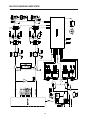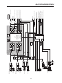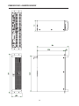
1
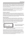
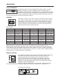
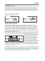
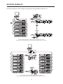
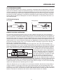
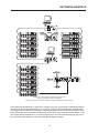
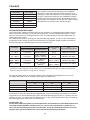
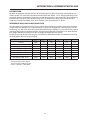
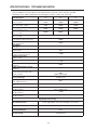
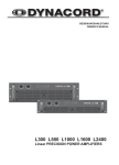
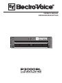
OWNER‘S MANUAL BEDIENUNGSANLEITUNG CONTENTS IMPORTANT SAFETY INSTRUCTIONS IMPORTANT SERVICE INSTRUCTIONS DESCRIPTION UNPACKING & WARRANTY INSTALLATION NOTES FRONT VIEW REAR VIEW INPUT A / INPUT B PARALLEL CONNECTION DSP OUT CONTROL PORT RS-232 INTERFACE ADDRESS REMOTE CAN-BUS EASY REMOTE POWER AMP OUTPUT GROUND-LIFT SWITCH LIMITER BRIDGED MODE CABLING LF-CONNECTION CORDS REMOTE CONTROL NETWORK NETWORK EXAMPLES CAN-BUS CABLING SPECIFICATIONS MAINS OPERATION & RESULTING TEMP SPECIFICATIONS / TECHNISCHE DATEN BLOCK DIAGRAM AMPLIFIER BLOCK DIAGRAM RCM-24 DIMENSIONS / ABMESSUNGEN ....................... ....................... ....................... ....................... ....................... ....................... ....................... ....................... ....................... ....................... ....................... ....................... ....................... ....................... ....................... ....................... ....................... ....................... ....................... ....................... ....................... ....................... ....................... ....................... ....................... ....................... ....................... ....................... ....................... ....................... 3 3 4 5 5 6 7 7 7 7 7 8 8 8 9 9 9 10 10 11 11 11 12 14 14 15 32 34 35 36 INHALT WICHTIGE SICHERHEITSHINWEISE WICHTIGE SERVICEHINWEISE BESCHREIBUNG AUSPACKEN & GARANTIE INSTALLATIONSHINWEISE FRONTSEITE RÜCKSEITE INPUT A / INPUT B PARALLEL DSP OUT CONTROL PORT RS-232 INTERFACE ADDRESS REMOTE CAN-BUS EASY REMOTE ENDSTUFENAUSGÄNGE GROUND-LIFT SCHALTER LIMITER BRIDGED MODE VERKABELUNG NF-VERBINDUNGSKABEL REMOTE CONTROL NETZWERK NETZWERK-BEISPIELE CAN-BUS LEITUNGSSPEZIFIKATIONEN NETZBETRIEB & WÄRMEENTWICKLUNG SPECIFICATIONS / TECHNISCHE DATEN BLOCK DIAGRAM AMPLIFIER BLOCK DIAGRAM RCM-24 ABMESSUNGEN 2 ....................... ....................... ....................... ....................... ....................... ....................... ....................... ....................... ....................... ....................... ....................... ....................... ....................... ....................... ....................... ....................... ....................... ....................... ....................... ....................... ....................... ....................... ....................... ....................... ....................... ....................... ....................... ....................... ....................... ....................... 19 19 20 21 21 22 23 23 23 23 23 24 24 24 25 25 25 26 26 27 27 27 28 30 30 31 32 34 35 36 IMPORTANT SAFETY INSTRUCTIONS The lightning flash with arrowhead symbol, within an equilateral triangle is intended to alert the user to the presence of uninsulated „dangerous voltage“ within the product’s enclosure that may be of sufficient magnitude to constitute a risk of electric shock to persons 1. 2. 3. 4. 5. 6. 7. 8. 9. 10. 11. The exclamation point within an equilateral triangle is intended to alert the user to the presence of important operating and maintance (servicing) instructions in the literature accompanying the appliance. Read these instructions. Keep these instructions. Heed all warnings. Follow all instructions. Do not use this apparatus near water. Do not expose this apparatus to dripping or splahing and ensure that no objects filled with liquids, such as vases, are placed on this apparatus. Clean only with a dry cloth. Do not block any of the ventilation openings. Install in accordance with the anufactures instructions. Do not install near any heat sources such as radiators, heat registers, stoves, or other apparatus (including amplifiers) that produce heat. Only use attachments/accessories specified by the manufacturer. Refer all servicing to qualified service personnel. Servicing is required when the apparatus has been damaged in any way, such as power-supply cord or plug is damaged, liquid has been spilled or objects have fallen into the apparatus, the apparatus has been exposed to rain or moisture, does not operate normally, or has been dropped To completely disconnect mains power from this apparatus, the power supply cord must be unplugged.. For US and CANADA only: Do not defeat the safety purpose of the grounding-type plug. A grounding type plug has two blades and a third grounding prong. The wide blade or the third prong are provided for your safety. When the provided plug does not fit into your outlet, consult an electrican for replacement of the absolete outlet. IMPORTANT SERVICE INSTRUCTIONS CAUTION: 1. 2. 3. 4. 5. 6. 7. 8. These servicing instructions are for use by qualified personnel only. To reduce the risk of electric shock, do not perform any servicing other than that ontained in the Operating Instructions unless you are qualified to do so. Refer all ervicing to qualified service personnel. Security regulations as stated in the EN 60065 (VDE 0860 / IEC 65) and the CSA E65 - 94 have to be obeyed when servicing the appliance Use of a mains separator transformer is mandatory during maintenance while the appliance is opened, needs to be operated and is connected to the mains Switch off the power before retrofitting any extensions, changing the mains voltage or the output voltage. The minimum distance between parts carrying mains voltage and any accessible metal piece (metal enclosure), respectively between the mains poles has to be 3 mm and needs to be minded at all times. The minimum distance between parts carrying mains voltage and any switches or breakers that are not connected to the mains (secondary parts) has to be 6 mm and needs to be minded at all times. Replacing special components that are marked in the circuit diagram using the security symbol (Note) is only rmissible when using original parts. Altering the circuitry without prior consent or advice is not legitimate. Any work security regulations that are applicable at the location where the appliance is being serviced have to be strictly obeyed. This applies also to any regulations about the work place itself. All instructions concerning the handling of MOS - circuits have to be observed. NOTE: SAFETY COMPONENT ( MUST BE REPLACED BY ORIGINAL PART ) 3 DESCRIPTION Congratulations! With buying an Electro-Voice PRECISION SERIES power amplifier you have chosen an appliance that employs the most advanced technology. P-Series power amps combine outstanding audio performance, highest reliability and operational stability. Each power amplifier employs an RCM-24 Remote Control module allowing centralized configuration, control and monitoring of all relevant power amp parameters (like output current, output voltage, load impedance, etc.). The gapless protection circuitry concept not only prevents the power amp itself but also the connected loudspeaker systems from being damaged. These extensive protections include Dynamic Audio Limiters, DC/HF-Protections, Back-EMF-Protection, Inrush Current Limiter, Short Circuit Protection and of course Thermal Overload Protection for the output transistors and mains transformers. Four-speed high performance fans guarantee outstanding thermal stability at absolute low running noise. The ventilation is directed front-to-rear allowing trouble-free operation even in smaller amp-racks. Comprehensively dimensioned power supply units with low-leakage toroidal transformers provide extensive headroom far above the stated nominal power. Mechanical construction and workmanship also comply with the highest precision manufacturing standards. The rigid sheet steel chassis resists even the most wearing tour operation. The RCM-24 provides full-size overview of the system’s entire status and control over all relevant system parameters at any time. The RCM-24 module allows integration into a Remote Control Network consisting of up to 250 power amps. The Windows Software IRIS – Intelligent Remote & Integrated Supervision – allows controlling and monitoring an entire PA-system from a single or several PCs. Any operational status like initial power-on status, temperature, modulation, limiting, activation of protections, deviation in the load impedance, etc., are centrally registered and displayed, which provides the opportunity to take specific measures prior to the occurrence of critical operational states. Programming an automatic response for exceeding or falling below specific limits is possible as well. All parameters, e.g. power-on/off, levels, muting, filters, etc. can be controlled in real-time and saved in any power amp. Monitoring the connected loudspeaker systems is performed through measuring output currents and –voltages of the two power amplifier channels. Each time the signal falls below or exceeds set limit values is immediately indicated and logged, thus detecting and indicating short circuits and line interruption during normal operation. The integrated impedance test function allows more precise checking the connected loudspeaker systems. The integrated signal generator is employed together with the current/voltage testing to measure the connected loudspeakers’ and cable’s impedance plus over the entire frequency range. The resulting impedance graph is displayed on the PC-screen. Comparing the measured impedance progression to a reference value is possible at all times, which allows recognizing even the slightest loudspeaker defects or irregularities. 4 DESCRIPTION Next to controlling and monitoring, the RCM-24 Remote Control module provides comprehensive signal processing functions. It includes a total of 20 parametric filter–, X-over functions, delays, routing and level control as well as compressors and limiters per channel. All parameters can be freely edited and stored in the module’s 8 user presets. Independent from network control all DSP-settings (filter, delay, level) are maintained in case of failure. Additionally, the control inputs of the power amps can be used for network-independent switching to another preset (e.g. alarm settings with maximum energy for voice and text announcements). Therefore, P-Series amps with RCM-24 modules installed fulfil even the highest safety requirements. When designing the RCM-24, uncompromising audio quality was the highest maxim. AD/DAconversion is performed at a resolution of 24-bit and 128-times oversampling with linear phase; the internal word length is 48 bits. With this the RCM-24‘s dynamic range reaches 115 dB, which is an absolute peak value for digital audio appliances. All configuration, control and monitoring details of P-Series power amps are explained in the documentation accompanying the PC Windows software IRIS. UNPACKING & WARRANTY Carefully open the packaging and take out the power amplifier. Next to the power amplifier itself, the package also includes this owner’s manual, the warranty certificate, four stand-feet, six screw-on connectors (1x 2-pole, 4x 3-pole, 1x 6-pole) plus a set of rack shelf mounting adapters. Please inspect carefully whether all information in the warranty certificate has been filled in completely, since only a completely filled in warranty certificate entitles you to stake any warranty claims. The appliance comes with a 36 months warranty, starting with the date when receiving the good from your dealer. Therefore, keep the original invoice together with the warranty certificate at a safe place. INSTALLATION NOTES 31.75 11/4“ 44.45 13/4“ Generally, installing or mounting power amps should be carried out in a way that guarantees continuously unopposed front-to-rear air circulation. When including an appliance in a closed cabinet or rack shelf system make sure to provide sufficient ventilation. Leave a gap of at least 60mm x 330mm (up to the cabinet’s top ventilation louvers) for air circulation between the rear of the power amplifier and the cabinet’s/rack’s rear wall. Make sure to leave at least 100mm of space above the cabinet or rack shelf system. Since the temperature inside of the cabinet or rack shelf system can easily rise up to 40°C during operation, bearing in mind the maximally allowable environmental temperature during operation for all other appliances installed in the same rack shelf system is mandatory. (also refer to “MAINS OPERATION & RESULTING TEMPERATURE”) Caution: The use of rails or optionally available rack adapters is mandatory as well when installing the appliance in a rack shelf system to prevent the front panel from bending. 44.45 151/2“ For problem-free operation exceeding the maximally allowable environmental temperature or +40°C is not permissible. The power amplifier has to be protected against: dripping or splashing water, direct sunlight, high temperatures or direct influence of heat sources, high humidity, extensive dust and vibrations. Condensation on internal parts may occur after transporting the power amplifier from a cold into a warmer environment. In that case operation is only permissible after the appliance has gained the new temperature (after approximately one hour). If foreign objects or liquids have entered the power amplifier’s enclosure make sure to instantly separate the appliance from the mains power and contact an authorised DYNACORD service centre for inspection before continuing operation. Do not use any sprays or solvents for cleaning the appliance, because they might severely damage the surface of the enclosure or lead to dangerous fire hazard. 5 FRONT VIEW Use the POWER switch located in the centre of the front panel to switch the appliance’s power on. The soft-start function prevents current inrush peaks on the mains, which in addition prevents the mains line protection switch from activating during power-on operation of the power amplifier. The loudspeaker outputs are activated via relay switching with a delay of approximately 2 seconds effectively attenuating eventual power-on noise. The PROTECT LED lights during the delay time and the fans run at maximum speed. This is normal to confirm the immaculate operation of the protection circuitry. Upon power-on, all power amps with RCM-24 Module installed regain the state of operation prior to the last power-off. For example: if a power amplifier had been switched off using the POWER-switch while being in Standby mode, upon power-on it restarts in this exact mode. This indicator lights when the power amplifier has been switched on. Causes for the POWER-indicator not lighting are: the appliance is not connected to the mains network, a defective primary fuse, or the power amplifier is set to stand-by operation (STAND-BY LED lights). This indicator light when the power amplifier is in stand-by mode, which can be activated from the RCM-24 or via Easy Remote. In stand-by operation only the internal auxiliary power supply unit is activated. The main power supply unit is separated from the mains. The PROTECT LED lights indicating that one of the internal protection circuits against thermal overload, short-circuit, Back-EMF, HF-occurrence at the output, etc., has been activated. In that case, the output relays separate the power amps from the load connected to prevent the connected loudspeaker systems and the power amplifiers as well from being damaged. Whatever caused the fault – e.g. a shortcircuited speaker cable – needs to be remedied. In case of thermal overload you have to wait until the power amplifier automatically regains normal operation. The OUT LED lights as soon as an audio signal of approximately 30dB below full modulation is present. The LED is dimmed when speaker cables are short-circuited or a protection circuit has been activated. The 0dB LED lights when the power amplifier is driven at its maximum. Higher input voltage does not result in higher peak output voltage. This indicator lights as soon as the integrated dynamic limiter is activated and the power amplifier is driven at the clipping limit or generally at its maximum capacity. Short-term blinking is not a problem, since the internal limiter trims input levels of up to +21dBu down to a S/N-ratio of approximately 1%. If, on the other hand, this LED lights constantly, reducing the volume is recommended to prevent the loudspeaker systems connected from being damaged by probable overload. 6 REAR VIEW INPUT A / INPUT B The inputs INPUT A & INPUT B are electronically balanced offering an input sensitivity of +6dBu (1.55V) for direct connection of mixing consoles, etc. Connection can be established via the XLR-type input connectors or the supplied screw-on connectors, which are connected in parallel. The pin-assignment of the XLR-type input connectors is according to the IEC 268 standard. In case floating inputs are needed, retrofitting optionally available input transformers is possible. One extension-kit NRS 90208 (Order-No. 121 641) per channel is needed. PARALLEL CONNECTION Connection can be established via the XLR-type input connectors INPUT A / INPUT B or the supplied screw-on connectors which are connected in parallel. In addition, using the PARALLEL-connectors provides the possibility for connecting the input signal through to feed additional power amplifiers, without the need for extra splitter-cables. DSP OUT The DSP output signal – i.e. the post-digital-signal-processing-unit audio signal – is present at the DSP OUT. The DSP output signal is simultaneously fed to the power amplifier output stage and is correspondingly amplified present at the power amp’s main outputs. The DSP OUT can be utilized for feeding the digitally processed audio signal from the RCM-24 Remote Control Module to additional power amplifiers (without DSP-module); e.g. for increasing the overall output power. With a nominal level of +6dBu and a maximum level of +21dBu (8.7V) the output signal is electronically balanced. Output impedance is 100Ω. CONTROL PORT The CONTROL PORT offers two freely programmable control inputs and control outputs as well as the reference connections for ground potential and +5V. Using the PC Windows software IRIS, the control inputs can be configured and serve for instance for Power-On / Stand-by switching, preset switching or parameter control. The two control contacts IN1 / IN2 are internally set to +5V (open) via pull-up resistors. Activating the control inputs is possible by closing the contacts to ground potential (pin 3) via external switches, pushbuttons or relays. The two control outputs OUT1 / OUT2 are carried out as Open Collector Outputs. In non-active state (Off) they provide high ohmic resistance. In the active state (On) these outputs are connected to ground. The outputs serve for signalling internal operational states. They can be used for the direct triggering of LEDs, indication lights or relays. The +5V reference connector provides power supply for externally connected appliances with amperage of maximally 100mA. The control outputs allow signal indication of operational states (critical temperature, exceeding or decline of defined limit values, faults, etc.) at central operator desks or to other systems (fire alarm system, general alert system) even without PC. For further detail about configuring the control ports, please refer to the documentation accompanying the IRIS software. 7 REAR VIEW RS-232 INTERFACE The RS-232 interface is for connecting media control systems as well as building management systems providing control and monitoring of all parameters. Communication is established via an easily to implement ASCIIprotocol allowing trouble-free integration of Remote Amplifiers in media and touch panel control systems. For a programmer’s guide and complete protocol description, please refer to the documentation accompanying the IRIS software. ADDRESS The address selection switch allows setting the amplifier’s network address, which, within a CAN-network, can range from 01 to 250 (FA hex). Caution: Each address may exist only once within a network. Otherwise network conflicts might occur. Address setting has to be performed in hexadecimal code. The selection switch LOW represents the low-value digit while the HIGH-switch represents the high-value digit. Adress-Table: HIGH LOW Adress HIGH LOW Adress 0 0 Stand-alone 8 0 ... F 128 ... 143 0 1 ... F 1 ... 15 9 0 ... F 144 ... 159 1 0 ... F 16 ... 31 A 0 ... F 160 ... 175 2 0 ... F 32 ... 47 B 0 ... F 176 ... 191 3 0 ... F 48 ... 63 C 0 ... F 192 ... 207 4 0 ... F 64 ... 79 D 0 ... F 208 ... 223 5 0 ... F 80 ... 95 E 0 ... F 224 ... 239 6 0 ... F 96 ... 111 F 0 ... A 240 ... 250 7 0 ... F 112 ... 127 F B ... F reserved Address 0 (00 hex, factory-pre-set) ensures that the amplifier is separated from the remote communication, so that it does not appear in the system set-up even though it might be connected to the CAN-bus. When the amplifier is powered-on with its address set to “0”, all internal parameters are set to “0” respectively to bypass and the routing is set to 2-in-2. In that case the amplifier behaves absolutely linear, i.e. signal processing is deactivated. REMOTE CAN BUS Each amplifier employs two RJ-45 sockets for Remote CAN-bus connection. The sockets are parallel connected and serve as input as well as for connecting through of the Remote network. Common RJ-45 patch cables can be used for rack-shelf cabling. The CAN-bus needs to be terminated at both ends using a 120ohms termination plug. Detailed guidelines concerning cabling and bus length are provided in the chapter “REMOTE CONTROL NETWORK”. Both RJ-45 sockets additionally carry the balanced audio monitor signal. The nominal output level is +6dBu (1.55V) while the maximum output level is +21dBu (8.7V). Connector Pin-Assignment: (View of Contacts) 8 REAR VIEW The STATUS LED provides optical indication of CAN-bus traffic. When the power amplifier’s address is set to “00” so that it is separated from the CANbus, the STATUS LED blinks every 3 seconds. When the power amplifier’s address is set between “01” and “250” and no CAN-bus activity has taken place yet, the LED blinks every second. As soon as CAN-bus communication is recognized, the LED is activated for at least 100ms whenever the power amplifier actively sends data on the CAN-bus.The STATUS LED may also be activated from the PC. In this case, the LED of the according power amplifier blinks fast and steady while all other status-LEDs within the system stay dimmed. This function is useful for optically monitoring communication and for quickly identifying particular power amplifiers in extensive system installations (please also refer to the IRIS software documentation). EASY REMOTE Easy Remote provides a simple way to remotely power-on/off the power amplifier. The Easy Remote function is only useful for appliances not employing a RCM-24 Module. Controlling appliances with RCM-24 Module installed per Easy Remote is practically pointless. EASY REMOTE IN Leaving the pins of the EASY REMOTE IN socket open, i.e. when connecting +5V, the appliance power is switched on. When connecting the EASY REMOTE IN, i.e. when feeding 0V from the control output, the appliance enters standby mode. EASY REMOTE SLAVE The EASY REMOTE SLAVE connector provides connection for additional appliances with EasyRemote function (e.g. for switching several devices within a rack-shelf ON/OFF). The switching of the slave-units is delayed to prevent the mains fuses from blowing. POWER AMPLIFIER OUTPUTS SPEAKON-type connectors are provided for the power amplifier channels „A“ and „B“. The BRIDGED OUT connector for bridged operation has a plastic coverlid preventing inadvertent misconnection. When connecting loudspeaker systems, please mind the polarity according to the following diagram: GROUND-LIFT SWITCH The ground-lift switch allows eliminating noise loops. If the power amplifier is operated together with other equipment in a 19“ rack-shelf, setting the switch to its GROUNDED position is recommended. If the power amplifier is operated together with appliances with differing ground potentials, setting the switch to its UNGROUNDED position is recommended. 9 REAR VIEW LIMITER The integrated limiter provides reliable protection against signal clipping and has a switchable time constant. Leaving the switch set to SLOW is recommended for general use (factory pre-set status). When using the power amplifier as Mid/Hi power amp employed in active multi-way systems, setting the limiter switch to FAST is recommended. When using the power amplifier as low-frequency woofer power amp employed in active multi-way systems, setting the limiter switch to SLOW is recommended. BRIDGED MODE Switch for changing from normal (stereo) operation to bridged mode. In bridged mode the integrated power amplifiers operate in „push-pull“ operation. The output voltages of cannel „A“ and channel „B“ are doubled and present at the BRIDGED OUT connector. Channels „A“ and „B“ work phase-shifted in push-pull operation and may not be used as loudspeaker outputs. 10 CABLING LF-CONNECTION CORDS Choosing balanced cables (two conductors for the audio signal plus separate shielding mesh) with XLR-type connectors is recommended for LF-signal connection. Although connecting unbalanced cables to the power amplifier inputs is possible as well, using balanced cabling is always preferable. A great number of today’s audio appliances employ balanced outputs. With balanced cabling, the shield connects all metal enclosure parts and thus efficiently eliminates the introduction of noise and hum. XLR-type connector pin-assignment XLR (male) XLR (female) REMOTE CONTROL NETWORK The network of the remote power amps is based on the CAN-bus standard, which for years is especially popular in automotive, industrial and security applications. The CAN-bus is a balanced serial interface for command and data transmission. Controlling the power amplifiers is performed from a PC with IRIS – Intelligent Remote & Integrated Supervision – software installed. The UCC1 USB-CAN Converter serves as interface between the PC and the CAN-bus. Connecting up to 100 power amplifiers per CAN-Bus with a maximum total cable length of 1,000 meters is possible. An additional CAN-bus is needed for controlling more than 100 power amps while the IRIS software allows administering a total of 250 power amps. The network topology used by the CAN-bus is the so-called “bus or line topology”, i.e. all participants are connected via a single two-wire cable (Twisted-Pair cable, shielded or unshielded) with the cabling running from one participant on the bus to the next, allowing unlimited communication among all appliances included. In general, it does not matter whether a participant on the bus is a power amplifier or a UCC1 USB-CAN converter, so that both – UCC1 and the PC as well – can be inserted at any position. Incorporating several UCC1 and PCs on a single CAN-bus is also possible. A total of up to 100 appliances can be operated on a single CAN-bus. Since the CANinterfaces of all appliances are galvanically separated from the rest of the circuitry, network cabling also carries a common ground conductor (CAN_GND) ensuring that all CAN-interfaces in the network are connected to a common ground potential. The UCC1 provides the possibility for switching the CAN-ground to circuit-ground. Each participant on the bus system has two RJ-45 connectors for the Remote CAN-bus. These sockets are connected in parallel to serve as input and output (for connecting through) for the data transfer of the remote-network. The CAN-bus has to be terminated at both ends using 120 terminator plugs, two of which – CAN-TERM 120 – are supplied with the UCC1. Connect one of these to the RJ-45 socket of the first and the other to the socket of the last appliance on the CAN-bus. 11 NETWORK EXAMPLES The following diagrams show examples of the data-bus wiring for different order of size: System with 5 amps and one UCC1 / PC at the beginning of the bus Terminators at the UCC1 (first unit on the bus) and at amp 5 (last unit on the bus) System with 2 amp-racks and an UCC1 / PC in the middle Terminators at amp 6 (first unit on the bus) and amp 12 (last unit on the bus) 12 NETWORK EXAMPLES System with several amp-racks and several UCC1 / PCs UCC1s anywhere on the CAN-bus Terminators at amp 10 (first unit on the bus) and amp 16 (last unit on the bus) Next to the CAN-bus signal, network cabling also carries the balanced monitor audio signal for monitoring the power amp inputs and outputs. This monitor-bus allows software-controlled monitoring of the input and output signals of all power amps that are included in the remote network, without the need for additional wiring. The monitor signal is present at the UCC1’s XLR-type MONITOR Output connector for further distribution to (e.g.) a mixing console to be monitored via headphones or an active monitor speaker connected. 13 CAN-BUS Baud Rate Bus Length 500 kbit/s 100 m 250 kbit/s 250 m 125 kbit/s 500 m 62.5 kbit/s 1000 m 20 kbit/s 2500 m 10 kbit/s 5000 m The CAN-bus allows using different data rates, with the data rate being indirectly proportional to the bus length. Small networks allow baud rates up to 500kbit/s. For sizable dimensioned networks reducing the baud rate (minimum 10kbit/s) is necessary. The integration of repeaters is generally recommended when the bus-length exceeds 1,000m. CABLE SPECIFICATIONS According to the ISO 11898-2 standard, CAN-bus data transfer cabling has to be carried out using Twisted-Pair cables with or without shielding providing a characteristic impedance of 120Ω. Both ends of a CAN-bus need to be terminated with 120Ω termination-plugs. The maximum bus-length depends on the actual data transfer rate, the kind of data transfer cable being used, as well as the total number of participants on the bus. The following table shows the most essential coherencies for CAN-networks consisting of up 64 participants: Cable for data Transmission Termination max. Data Transfer Rate 0.25 ... 0.34 mm² AWG23, AWG22 124 Ω 1000 kbit/s at 40 m < 60 mΩ/m 0.34 ... 0.6 mm² AWG22, AWG20 127 Ω 500 kbit/s at 100 m 300 ... 600 m < 40 mΩ/m 0.5 ... 0.6 mm² AWG20 150 Ω ... 300 Ω* 100 kbit/s at 500 m 600 ... 1000 m < 26 mΩ/m 0.75 ... 0.8 mm² AWG18 150 Ω ... 300 Ω* 62.5 kbit/s at 1000 m Bus Length Resistance per Unit Length Cable Diameter 0 ... 40 m < 70 mΩ/m 40 ... 300 m * With longer cables and many participants on the CAN-bus, termination resistors with higher impedance than the specified 120Ω are recommended to reduce the ohmic load of the interface drivers and therefore the voltage drop between the two cable ends. The following table is meant for first assessment of necessary cable diameters for different bus lengths and bus-participant numbers: Bus Length Number of Appliance on the CAN-Bus 32 64 100 100 m 0.25 mm² or AWG24 0.34 mm² or AWG22 0.34 mm² or AWG22 250 m 0.34 mm² or AWG22 0.5 mm² or AWG20 0.5 mm² or AWG20 500 m 0.75 mm² or AWG18 0.75 mm² or AWG18 1.0 mm² or AWG17 Additionally, the length of branch lines – for participants that are not directly connected to the CAN-bus – is also of importance. For data transfer rates of up to 125kbit/s, the maximum length of a single stub cable should not exceed 2m. For higher bit rates a maximum length of only 0.3m is still permissible. The entire length of all branch lines should not exceed 30 m. General Note: As long as only short distances (up to 10m) are concerned, common RJ-45 patch cables with 100Ω characteristic impedance (AWG 24 / AWG 26) can be used for the cabling inside of a rackshelf system. The previously outlined guidelines for network cabling are mandatory as far as the rack-shelve interconnection or fixed installations are involved. 14 MAINS OPERATION & RESULTING TEMPERATURE MAINS OPERATION The following tables allow determining power supply and cabling requirements. The values of the column „Max. Output @ 4Ω” are relevant for “normal” operation. These values are based on operating the power amplifier with VDE-noise at 1/8 of the maximum output power, which approximately equates the load of the power amplifier being operated with a music signal at maximum volume possible, without noticeable clipping. RESULTING TEMPERATURE INSIDE THE POWER AMPLIFIER The power drawn from the mains network is converted into acoustic output power to feed the connected loudspeaker systems & heat. The difference between drawn power and dispensed power is called leakage power or dissipation (Pd). The amount of heat resulting from power dissipation might remain inside of a rack-shelf and needs to be diverted using appropriate measures. The following table provides auxiliary means for calculating the temperatures inside of a rack-shelf system/cabinet and the ventilation efforts necessary. The column “Pd” lists the leakage power in relation to different operational states. The column “BTU/hr” lists the dispensed heat amount per hour. P3000RL Normal Mode UMains [V] IMains [A] PMains [W] Pout [W] Pd [W] BTU/hr(3) Idling Max. Output @ 8Ω 230V 1.0 152 - 152 519 (1) 230V 13.8 2560 2 x 850 860 2934 (1) 230V 22.4 4330 2 x 1300 1730 5903 230V 13.9 2575 2 x 433 1709 5831 230V 7.8 1350 2 x 163 1024 3494 230V 8.0 1420 2 x 120 1180 4026 230V 21.6 4170 2 x 1200 1770 6040 230V 16.0 3020 2 x 610 1800 6142 Max. Output @ 4Ω 1⁄3 max. Output @ 4Ω (1) 1⁄8 max. Output @ 4Ω (2) Normal Operation (-10dB) @ 4Ω Nominal Operation (0dB) @ 4Ω Alarm Operation (-3dB) @ 4Ω (1) (1) (1) For approximation; when operating the appliance at 120V mains the stated current values need to be doubled. (1) modulated with sine signal (2) modulated with VDE-noise (3) 1BTU = 1055.06J = 1055.06Ws 15 16 BEDIENUNGSANLEITUNG INHALT WICHTIGE SICHERHEITSHINWEISE WICHTIGE SERVICEHINWEISE BESCHREIBUNG AUSPACKEN & GARANTIE INSTALLATIONSHINWEISE FRONTSEITE RÜCKSEITE INPUT A / INPUT B PARALLEL DSP OUT CONTROL PORT RS-232 INTERFACE ADDRESS REMOTE CAN-BUS EASY REMOTE ENDSTUFENAUSGÄNGE GROUND-LIFT SCHALTER LIMITER BRIDGED MODE VERKABELUNG NF-VERBINDUNGSKABEL REMOTE CONTROL NETZWERK NETZWERK-BEISPIELE CAN-BUS LEITUNGSSPEZIFIKATIONEN NETZBETRIEB & WÄRMEENTWICKLUNG SPECIFICATIONS / TECHNISCHE DATEN BLOCK DIAGRAM AMPLIFIER BLOCK DIAGRAM RCM-24 ABMESSUNGEN 18 ....................... ....................... ....................... ....................... ....................... ....................... ....................... ....................... ....................... ....................... ....................... ....................... ....................... ....................... ....................... ....................... ....................... ....................... ....................... ....................... ....................... ....................... ....................... ....................... ....................... ....................... ....................... ....................... ....................... ....................... 19 19 20 21 21 22 23 23 23 23 23 24 24 24 25 25 25 26 26 27 27 27 28 30 30 31 32 34 35 36 WICHTIGE SICHERHEITSHINWEISE Das Blitzsymbol innerhalb eines gleichseitigen Dreiecks soll den Anwender auf nicht isolierte Leitungen und Kontakte im Geräteinneren hinweisen, an denen hohe Spannungen anliegen, die im Fall einer Berührung zu lebensgefährlichen Stromschlägen führen können. Das Ausrufezeichen innerhalb eines gleichseitigen Dreiecks soll den Anwender auf wichtige Bedienungssowie Servicehinweise in der zum Gerät gehörenden Literatur aufmerksam machen. 1. 2. 3. 4. 5. Lesen Sie diese Hinweise. Heben Sie diese Hinweise auf. Beachten Sie alle Warnungen. Richten Sie sich nach den Anweisungen. Betreiben Sie dieses Gerät nicht in unmittelbarer Nähe von Wasser. Stellen Sie bitte sicher, dass kein Tropf- oder Spritzwasser ins Geräteinnere eindringen kann. Platzieren Sie keine mit Flüssigkeiten gefüllten Objekte, wie Vasen oder Trinkgefässe, auf dem Gerät ab. 6. Verwenden Sie zum Reinigen des Gerätes ausschliesslich ein trockenes Tuch. 7. Verdecken Sie keine Lüftungsschlitze. Beachten Sie bei der Installation des Gerätes stets die entsprechenden Hinweise des Herstellers. 8. Vermeiden Sie die Installation des Gerätes in der Nähe von Heizkörpern, Wärmespeichern, Öfen oder anderer Wärmequellen. 9. Verwenden Sie mit dem Gerät ausschliesslich Zubehör/ Erweiterungen, die vom Hersteller hierzu vorgesehen sind. 10. Überlassen Sie sämtliche Servicearbeiten und Reparaturen einem ausgebildeten Kundendiensttechniker. Bringen Sie das Gerät direkt zu unserem Kundendienst, wenn es beschädigt wurde oder eine Funktionsstörung zeigt. 11. Um das Gerät komplett spannungsfrei zu schalten, muss der Netzstecker gezogen werden. WICHTIGE SERVICEHINWEISE ACHTUNG: Diese Servicehinweise sind ausschliesslich zur Verwendung durch qualifiziertes Servicepersonal. Um die Gefahr eines elektrischen Schlages zu vermeiden, führen Sie keine Wartungsarbeiten durch, die nicht in der Bedienungsanleitung beschrieben sind, ausser Sie sind hierfür qualifiziert. Überlassen Sie sämtliche Servicearbeiten und Reparaturen einem ausgebildeten Kundendiensttechniker. 1. Bei Reparaturarbeiten im Gerät sind die Sicherheitsbestimmungen nach EN 60065 ( VDE 0860 ) einzuhalten. 2. Bei allen Arbeiten, bei denen das geöffnete Gerät mit Netzspannung verbunden ist und betrieben wird, ist ein Netz Trenntransformator zu verwenden. 3. Vor einem Umbau mit Nachrüstsätzen, Umschaltung der Netzspannung oder sonstigen Modifikationen ist das Gerät stromlos zu schalten. 4. Die Mindestabstände zwischen netzspannungsführenden Teilen und berührbaren Metallteilen (Metallgehäuse) bzw. zwischen den Netzpolen betragen 3 mm und sind unbedingt einzuhalten. Die Mindestabstände zwischen netzspannungsführenden Teilen und Schaltungsteilen, die nicht mit dem Netz verbunden sind (sekundär), betragen 6mm und sind unbedingt einzuhalten. 5. Spezielle Bauteile, die im Stromlaufplan mit dem Sicherheitssymbol gekennzeichnet sind, (Note) dürfen nur durch Originalteile ersetzt werden. 6. Eigenmächtige Schaltungsänderungen dürfen nicht vorgenommen werden. 7. Die am Reparaturort gültigen Schutzbestimmungen der Berufsgenossenschaften sind einzuhalten. Hierzu gehört auch die Beschaffenheit des Arbeitsplatzes. 8. Die Vorschriften im Umgang mit MOS - Bauteilen sind zu beachten. NOTE: SAFETY COMPONENT ( MUST BE REPLACED BY ORIGINAL PART ) 19 BESCHREIBUNG Herzlichen Glückwunsch! Sie haben sich mit einer Endstufe der PRECISION SERIES von ElectroVoice für ein Gerät modernster Technologie entschieden. Die Endstufen der P-Serie vereinen überragende Audio-Performance mit höchster Zuverlässigkeit und Betriebssicherheit. Jede Endstufe ist mit dem RCM-24 Remote Control Modul ausgestattet, welches die zentrale Konfiguration, Steuerung und Überwachung aller relevanten Endstufenparameter (wie Ausgangsstrom, -spannung, Lastimpedanz, ...) ermöglicht. Ein lückenloses Konzept an Protections schützt nicht nur die Endstufen, sondern auch die angeschlossenen Lautsprecher. Zu diesen Schutzschaltungen gehören dynamische Audio-Limiter, DC/HF-Protections, Back-EMF-Protection, Inrush Current Limiter, Short Circuit Protection und natürlich die Temperaturüberwachung der Endtransistoren und der Netztransformatoren. Die thermische Stabilität wird durch vierstufige Hochleistungslüfter mit sehr niedrigem Geräuschpegel gewährleistet. Die Luftführung ist Front-to-Rear, was den problemlosen Betrieb in grossen und schmalen Endstufen-Racks ermöglicht. Durch zwei grosszügig dimensionierte Netzteile mit streuarmen Ringkerntransformatoren wird ein grosser Headroom weit oberhalb der ausgewiesenen Nennleistung erzielt. Höchste Präzision ist auch in der mechanischen Konstruktion und Verarbeitung gewährleistet. Das robuste Stahlblech-Chassis ist besonders verwindungssteif und auf den harten Tourbetrieb ausgelegt. Mit dem RCM-24 hat man zu jeder Zeit einen vollständigen Überblick über den gesamten Systemzustand und die Kontrolle über alle relevanten Systemparameter. Das RCM-24 Modul erlaubt die Anbindung an ein Remote Control Netzwerk mit bis zu 250 Endstufen. Ein komplettes PASystem kann von einem oder mehreren PCs mit Hilfe der Windows Software IRIS – Intelligent Remote & Integrated Supervision – gesteuert und überwacht werden. Sämtliche Betriebszustände, z. B. Einschaltstatus, Temperatur, Aussteuerung, Limiting, Ansprechen von Schutzschaltungen, Abweichungender Lastimpedanz usw., werden zentral erfasst und dargestellt. Dadurch kann schon vor dem Auftreten von kritischen Betriebszuständen reagiert und gezielt eingegriffen werden. Eine automatische Reaktion auf Über- oder Unterschreitung bestimmter Grenzwerte ist ebenfalls programmierbar. Alle Parameter, z. B. Power On/Off, Level, Mute, Filter usw. sind in Echtzeit steuerbar und können in jeder Endstufe abgespeichert werden. Die angeschlossenen Lautsprecher werden durch Messung der Ausgangsströme und -spannungen der beiden Endstufenkanäle überwacht. Jede Über- oder Unterschreitung der eingestellten Grenzwerte wird sofort gemeldet und protokolliert. Kurzschlüsse oder Leitungsunterbrechungen werden so während des normalen Anlagenbetriebs erkannt und dargestellt. Eine wesentlich genauere Überprüfung der angeschlossenen Lautsprecher ermöglicht die integrierte Impedanz-Messfunktion. Dabei wird mit Hilfe des internen Signal-Generators und der Strom-/Spannungsmessung die Impedanz des oder der Lautsprecher plus der Zuleitungen über den gesamten Frequenzbereich gemessen und als Impedanzkurve am PC Bildschirm dargestellt. Der gemessene Impedanzverlauf kann jederzeit mit einem Referenzwert verglichen werden, wodurch schon geringste Lautsprecherdefekte oder Mängel erkennbar sind. 20 BESCHREIBUNG Neben der Steuerung und Überwachung stellt das RCM-24 Remote Control Modul umfangreiche Signalverarbeitungsfunktionen zur Verfügung. Enthalten sind insgesamt 20 parametrische Filter, X-Over Funktionen, Delays, Routing und Level Control, sowie Kompressor und Limiter pro Kanal. Sämtliche Parameter sind frei editierbar und können auf dem Modul in bis zu 8 User Memories abgespeichert werden. Unabhängig von der Kontrolle durch das Netzwerk bleiben in einem Havariefall alle DSP-Einstellungen (Filter, Delay, Level) erhalten. Ausserdem lassen sich die Steuereingänge der Endstufen zur netzwerkunabhängigen Umschaltung auf ein anderes Preset (z.B. Alarmierungs-Einstellung mit maximaler Energie im Sprachbereich) verwenden. Damit wird die P-Serie mit RCM-24 Modul auch höchsten Sicherheitsanforderungen gerecht. Beim Hardware-Design des RCM-24 wurde auf kompromisslose Audioqualität höchster Wert gelegt. Die AD/DA-Wandlung findet mit 24-Bit Auflösung und 128-fachem Oversampling mit linearer Phase statt; die interne Wortlänge ist 48 Bit. Damit erreicht das RCM-24 eine Dynamik von 115 dB, ein absoluter Spitzenwert für digitale Audiogeräte. Sämtliche Details zur Konfiguration, Steuerung und Überwachung der P-Series Endstufen finden Sie in der Dokumentation der PC Windows Software IRIS. AUSPACKEN & GARANTIE Öffnen Sie die Verpackung und entnehmen Sie die Endstufe. Zusätzlich zu dieser Bedienungsanleitung liegen dem Gerät die Garantiekarte, vier Gerätefüsse, sechs Schraub-Steckverbinder (1 mal 2-polig, 4 mal 3-polig, 1 mal 6-polig) und ein Satz Rackeinbauwinkel bei. Überprüfen Sie bitte ob die Garantiekarte vollständig ausgefüllt ist, denn nur so können Sie etwaige Garantieansprüche geltend machen. Sie haben auf das Gerät 36 Monate Garantie, die ab dem Zeitpunkt der Aushändigung durch den Händler gilt. Bewahren Sie zur Garantiekarte auch den Kaufbeleg, der den Termin der Übergabe festlegt, auf. INSTALLATIONSHINWEISE Generell sind die Endstufen so aufzustellen oder zu montieren, daß die Luftzufuhr an der Frontseite und die Entlüftung an der Geräterückseite nicht behindert wird. Für den Einbau in Gehäuse und Gestellschränke ist zu beachten, daß eine ausreichende Belüftung der Geräte möglich ist. Zwischen der Endstufen Rückseite und der Schrank/Rack-Innenseite ist ein freier Luftkanal von mindestens 60mm x 330mm bis zur oberen Rack- oder Schrankentlüftung vorzusehen. Oberhalb des Schrankes soll ein freier Raum von mindestens 100mm für die Entlüftung vorgesehen werden. Da beim Betrieb die Temperatur im Gehäuse- oder Schrank bis zu 40°C ansteigen kann, muß die maximal zulässige Umgebungstemperatur der übrigen im Gestellschrank befindlichen Geräte beachtet werden. (siehe „NETZBETRIEB UND WÄRMEENTWICKLUNG“) 31.75 11/4“ 44.45 13/4“ Beim Einbau in Gestellschränken sollen in jedem Fall Einbauschienen oder die beiliegenden Rackeinbauwinkel verwendet werden, um ein Verwinden der Frontblende zu verhindern. 44.45 151/2“ Achtung: Die max. Umgebungstemperatur von +40°C soll für störungsfreien Betrieb nicht überschritten werden. Die Endstufe ist zu schützen vor: Tropf- oder Spritzwasser, direkter Sonnenbestrahlung, hoher Umgebungstemperatur oder unmittelbarer Einwirkung von Wärmequellen, hoher Luftfeuchtigkeit, starken Staubablagerungen und starken Vibrationen. Wenn die Endstufe direkt von einem kalten an einen warmen Ort gebracht wird, kann sich Feuchtigkeit auf Innenteilen niederschlagen. Das Gerät darf erst in Betrieb genommen werden, wenn es sich auf die geänderte Temperatur erwärmt hat (nach etwa einer Stunde). Sollte ein fester Gegenstand oder Flüssigkeit in das Gehäuse gelangen, trennen Sie sofort das Gerät von der Stromquelle ab und lassen Sie das Gerät von einer autorisierten Servicestelle überprüfen, bevor Sie es weiterverwenden. Zur Reinigung des Gerätes dürfen keine Sprühmittel verwendet werden, da diese dem Gerät schaden und sich plötzlich entzünden können. 21 FRONTSEITE Mit dem POWER Schalter in der Mitte der Frontblende wird das Gerät eingeschaltet. Eine SoftstartSchaltung vermeidet dabei Einschaltstromspitzen auf der Netzleitung. Dadurch wird verhindert, dass der Leitungsschutzschalter des Stromnetzes beim Einschalten der Endstufe anspricht. Die Lautsprecher werden über die Ausgangsrelais um ca. 2 Sekunden verzögert zugeschaltet, wodurch etwaige Einschaltgeräusche effektiv unterdrückt werden. Während dieser Verzögerung leuchtet die PROTECT LED und die Lüfter laufen mit maximaler Geschwindigkeit. Dies ist normal und bestätigt die einwandfreie Funktion der Schutzschaltungen. Alle Endstufen mit RCM-24 Modul befinden sich nach dem Einschalten wieder in dem Zustand, in dem sie ausgeschaltet wurden. Wurde das Gerät z.B. im Standby Modus per POWER Schalter ausgeschaltet, so wird es sich nach dem Einschalten wieder in diesem Modus befinden. Diese Anzeige leuchtet auf, wenn die Endstufe eingeschaltet ist. Falls die POWER Anzeige nicht leuchtet, ist das Gerät nicht mit dem Stromnetz verbunden, die Primärsicherung defekt oder die Endstufe befindet sich im Standby Modus (STANDBY LED leuchtet). Diese Anzeige leuchtet, wenn sich die Endstufe im Standby Modus befindet, welcher über das RCM-24 oder über Easy Remote aktiviert werden kann. Im Standby Modus ist nur das interne Hilfsnetzteil aktiviert. Das Leistungsnetzteil ist netzseitig getrennt. Wenn die PROTECT-Anzeige aufleuchtet, hat eine der internen Schutzschaltungen wie Übertemperatur, Kurzschluss, Back-EMF, Hochfrequenz am Ausgang.... angesprochen. Die Endstufen werden in diesem Fall über die Ausgangsrelais von der Last getrennt, um etwaige Schäden an den Lautsprechern oder der Endstufe selbst zu verhindern. Die Fehlerursache, beispielsweise eine kurzgeschlossene Lautsprecherleitung muss beseitigt werden. Bei Überhitzung muss einige Zeit gewartet werden, bis die Endstufe sich selbständig wieder in den normalen Betriebszustand schaltet. Die OUT-LED beginnt ca. 30dB unter Vollaussteuerung zu leuchten. Bei Kurzschluss von Lautsprecherleitungen oder Ansprechen einer Schutzschaltung verlischt diese Anzeige. Die 0dB Anzeige leuchtet auf, wenn die Endstufe mit maximaler Aussteuerung betrieben wird. Eine höhere Eingangsspannung hat keine Erhöhung der Spitzenausgangsspannung zur Folge. Diese Anzeige leuchtet auf, sobald der eingebaute dynamische Limiter anspricht und die Endstufe an der Aussteuerungsgrenze oder generell im Grenzbereich betrieben wird. Kurzzeitiges Aufleuchten ist dabei unproblematisch, da der interne Limiter Eingangspegel bis zu +21dBu auf einen Klirrfaktor von ca. 1% ausregeln kann. Leuchtet diese LED jedoch dauerhaft sollte die Lautstärke reduziert werden, um etwaige Überlastungsschäden der angeschlossenen Lautsprecherboxen zu vermeiden. 22 RÜCKSEITE INPUT A / INPUT B Die Eingänge INPUT A & INPUT B sind elektronisch symmetrisch mit einer Eingangsempfindlichkeit von +6dBu (1.55V) für den direkten Betrieb mit Mischpulten usw. ausgelegt. Der Anschluss kann entweder über die XLR-Eingangsbuchsen oder die parallelgeschalteten Schraubsteckverbindungen, die im Lieferumfang enthalten sind, erfolgen. Die XLR-Eingangsbuchsen sind nach IEC Norm 268 beschaltet. Für den Fall, dass die Eingänge potenzialfrei sein müssen, ist die Nachrüstung von Eingangsübertragern vorgesehen. Es wird dazu je Kanal der Nachrüstsatz NRS 90208 (Nr. 121 641) benötigt. PARALLEL Das Eingangssignal kann entweder über die XLR-Buchsen INPUT A / INPUT B oder über die parallelgeschalteten Schraubsteckverbindungen erfolgen. Die Buchsen PARALLEL ermöglichen aber auch ein einfaches „Durchschleifen“ des Signals zu weiteren Endstufen ohne aufwändige Splitkabel. DSP OUT An der Buchse DSP OUT liegt das DSP-Ausgangssignal, also das Signal hinter dem digitalen Signalprocessing, an. Dieses Signal wird gleichzeitig in den Leistungsblock der Endstufe eingespeist und gelangt entsprechend verstärkt an die Endstufenausgänge. Der Ausgang DSP OUT kann verwendet werden, um weitere Endstufen (ohne DSP Modul) mit dem verarbeiteten Signal aus dem RCM-24 Remote Control Modul zu versorgen, z.B. zur Leistungserweiterung. Das Ausgangssignal ist elektronisch symmetrisch, der Nennpegel beträgt +6dBu, der Maximalpegel beträgt +21dBu (8.7V). Die Ausgangsimpedanz beträgt 100Ω. CONTROL PORT Der CONTROL PORT enthält zwei frei-programmierbare Steuereingänge und Steuerausgänge, sowie die Referenzanschlüsse für Masse und +5V. Die Steuereingänge sind mit Hilfe der PC Windows Software IRIS konfigurierbar, und dienen z. B. zur Power On / Standby Umschaltung, zur Presetumschaltung oder zur Parameterkontrolle. Die beiden Steuerkontakte IN1 / IN2 liegen intern über Pull-Up Widerstände auf +5V (offen). Zum Aktivieren können die Steuereingänge über externe Schalter, Taster oder Relais gegen Masse (Pin 3) geschlossen werden. Die beiden Steuerausgänge OUT1 / OUT2 sind Open Collector Outputs, die im nichtaktiven Zustand (Off) hochohmig sind. Im aktiven Zustand (On) sind die Ausgänge gegen Masse geschlossen. Die Ausgänge dienen zur Signalisierung interner Zustände und können direkt LEDs, Kontrollleuchten oder Relais ansteuern. Der +5V Referenzanschluss dient zur Versorgung der extern angeschlossenen Elemente mit einem Strom bis zu 100mA max. Über die Steuerausgänge können Betriebszustände (kritische Temperatur, Über- oder Unterschreitung definierter Grenzwerte, Fehler, usw.) an zentrale Bedienplätze oder andere Systeme (Brandmeldeanlage, Alarmierungsanlage) auch ohne PC gemeldet werden. Nähere Hinweise zur Konfiguration des Control Ports finden Sie in der IRIS Dokumentation. 23 RÜCKSEITE RS-232 INTERFACE Das RS-232 Interface dient als Schnittstelle zu Mediensteuerungssystemen bzw. Gebäudemanagementsystemen. Über RS-232 können sämtliche Parameter gesteuert und abgefragt werden. Die Kommunikation erfolgt über ein einfach zu implementierendes ASCII Protokoll. Auf diese Weise können die Remote Verstärker problemlos in Medien- und Touchpanel-Steuerungen integriert werden. Programmierhinweise und eine vollständige Protokollbeschreibung finden Sie in der IRIS Dokumentation. ADDRESS Mit Hilfe der Adress-Wahlschalter stellen Sie die Netzwerk-Adresse des Verstärkers ein. In einem CAN-Netzwerk können Sie die Adressen 01 bis 250 (FA hex) verwenden. Achtung: Jede Adresse darf im System nur einmal vorkommen, da es sonst zu Netzwerk-Konflikten kommt. Die Adresseinstellung erfolgt in Hexadezimal. Der Wahlschalter LOW ist das niederwertige Digit, der Schalter HIGH ist das höherwertige Digit. Adress-Tabelle: HIGH LOW Adresse HIGH LOW Adresse 0 0 Stand-alone 8 0 ... F 128 ... 143 0 1 ... F 1 ... 15 9 0 ... F 144 ... 159 1 0 ... F 16 ... 31 A 0 ... F 160 ... 175 2 0 ... F 32 ... 47 B 0 ... F 176 ... 191 3 0 ... F 48 ... 63 C 0 ... F 192 ... 207 4 0 ... F 64 ... 79 D 0 ... F 208 ... 223 5 0 ... F 80 ... 95 E 0 ... F 224 ... 239 6 0 ... F 96 ... 111 F 0 ... A 240 ... 250 7 0 ... F 112 ... 127 F B ... F reserviert Die Adresse 0 (00 hex, Auslieferungszustand) sorgt dafür, dass der Verstärker von der Remote-Kommunikation getrennt ist, und somit nicht mehr im System erscheint, auch wenn er am CAN-Bus angesteckt ist. Wenn der Verstärker mit Adresse 0 eingeschaltet wird, werden sämtliche internen Parameter auf 0 bzw. Bypass und das Routing auf 2-in-2 gestellt. Der Verstärker verhält sich dann völlig linear, die Signalverarbeitungsfunktionen sind deaktiviert. REMOTE CAN BUS Jeder Verstärker hat zwei RJ-45 Buchsen für den Remote CAN-Bus. Die Buchsen sind parallel geschaltet und dienen als Eingang und zum Weiterschleifen des Remote-Netzwerkes. Zur Verkabelung im Rack können handelsübliche RJ-45 Netzwerkkabel verwendet werden. Der CAN-Bus benötigt an beiden Enden einen Abschluss-Stecker mit 120 Ohm Abschlusswiderstand. Ausführliche Richtlinien zur Verdrahtung und Buslänge finden Sie im Kapitel „REMOTE CONTROL NETZWERK“. An den beiden RJ-45 Buchsen liegt auch das symmetrische Audio-Monitorsignal. Der Nenn-Ausgangspegel beträgt +6dBu (1.55V), der maximale Ausgangspegel ist +21dBu (8.7V). Steckerbelegung: (Ansicht Kontaktseite) 24 RÜCKSEITE Die LED STATUS dient zur Kontrolle der Kommunikation am CAN-Bus. Wenn die Adresse 00 eingestellt und die Endstufe softwaremässig vom CAN-Bus abgekoppelt ist, blinkt die LED regelmässig alle 3 Sek. kurz auf. Wenn eine Adresse zwischen 01 und 250 eingestellt ist, aber noch keine CAN-Bus Aktivität stattgefunden hat, blinkt die LED regelmässig jede Sekunde kurz auf. Sobald eine Kommunikation am CAN-Bus erkannt wurde, wird die LED immer dann für mindestens 100 ms aktiviert, wenn die Endstufe selbst Daten auf den CAN-Bus sendet. Die STATUS LED kann auch vom PC aktiviert werden. Die LED der betreffenden Endstufe blinkt dann in einem schnellen regelmässigen Rhythmus, alle anderen Status-LEDs im System bleiben dunkel. Diese Funktion dient zur Überprüfung der Kommunikation und zur schnellen Identifikation einer Endstufe in einem grösseren System (s. a. IRIS Dokumentation). EASY REMOTE Über Easy-Remote kann die Endstufe auf einfache Weise ferngesteuert einund ausgeschaltet werden. Die Easy Remote Funktion kommt nur bei Geräten ohne RCM-24 Modul zum Tragen. Eine Steuerung von Geräten mit RCM-24 Modul per Easy Remote ist nicht sinnvoll. EASY REMOTE IN Werden die Pins der EASY REMOTE IN Buchse offen gelassen bzw. mit +5V beaufschlagt, so schaltet das Gerät ein. Bei einer Verbindung der Pins oder 0V vom Steuerausgang schaltet das Gerät in den Standby Modus. EASY REMOTE SLAVE An EASY REMOTE SLAVE können weitere Geräte mit Easy Remote Funktion angeschlossen werden (z.B. zur Rack-ON/OFF Steuerung bei mehreren Geräten in einem Rack). Das Einschalten der Slave-Geräte erfolgt zeitverzögert um ein Ansprechen von Netzsicherungen zu vermeiden. ENDSTUFENAUSGÄNGE Für die Endstufenkanäle A und B sind jeweils SPEAKON Ausgangsbuchsen vorgesehen. Die BRIDGED OUT Buchse für den Brückenbetrieb ist mit einem Kunststoffdeckel geschlossen, um Anschlussfehler zu vermeiden. Bitte beachten Sie beim Anschluss von Lautsprechern die Polarität entsprechend der nachfolgenden Zeichnung: GROUND-LIFT SCHALTER Mit dem Groundlift-Schalter können Sie Brummschleifen verhindern. Wenn die Endstufe zusammen mit anderen Geräten in einem 19“-Rack betrieben wird, sollte der Schalter in Stellung GROUNDED stehen. Wird die Endstufe mit Geräten mit unterschiedlichem Erdungspotenzial betrieben, sollte der Schalter in Stellung UNGROUNDED stehen. 25 RÜCKSEITE LIMITER Der eingebaute Limiter zur Vermeidung von Übersteuerungen ist in seiner Zeitkonstante umschaltbar. Normalerweise sollte die Stellung SLOW benutzt werden (Auslieferungszustand). Bei Verwendung der Endstufe als Mittel-Hochtonendstufe in aktiven Mehrwegsystemen sollte der Limiter in Position FAST betrieben werden. Bei Verwendung der Endstufe als Bassendstufe in aktiven Mehrwegsystemen sollte der Limiter in Position SLOW betrieben werden. BRIDGED MODE Schalter zum Umschalten von Normal- (Stereo) in den Bridged-Mode. Im Bridged-Mode arbeiten die eingebauten Endstufen im „Gegentakt“ und an der Bridged Buchse erscheint die doppelte Ausgangsspannung von Kanal A und B. Kanal A und B arbeiten also gegeneinander phasengedreht und dürfen nicht mehr als Lautsprecherausgänge benutzt werden. 26 VERKABELUNG NF-VERBINDUNGSKABEL Als NF-Verbindung wählen Sie am besten symmetrisch ausgelegte Kabel (2 Signaladern + Schirmgeflecht) mit XLR-Stecker. Obwohl alle Endstufeneingänge auch unsymmetrisch belegt werden können, stellt ein symmetrisch ausgeführtes NF-Verbindungskabel die bessere Alternative zu einer unsymmetrischen Verbindung dar. Die meisten Audiogeräte verfügen über symmetrisch aufgebaute Ausgänge. Der Schirm im Kabel verbindet bei symmetrischer Signalführung alle metallischen Gehäuse und verhindert dadurch lückenlos ein Einkoppeln von externen Störsignalen, im wesentlichen Brummen, auf den Audiosignalpfad. XLR-Steckerbelegung XLR (male) XLR (female) REMOTE CONTROL NETZWERK Das Netzwerk der Remote Endstufen basiert auf dem CAN-Bus Standard, der sich im Automotive-, Industrie- und Sicherheits-Bereich durchgesetzt und über Jahre hinweg bewährt hat. Der CAN-Bus ist eine symmetrische serielle Schnittstelle zur Übertragung von Kommandos und Daten. Die Steuerung der Endstufen erfolgt von einem PC mit IRIS Intelligent Remote & Integrated Supervision Software. Als Interface zwischen PC und CAN-Bus dient der UCC1 USB-CAN Converter. Pro CAN-Bus lassen sich 100 Endstufen bis zu einer maximalen Kabellänge von 1000 Metern anschliessen. Wenn mehr als 100 Endstufen kontrolliert werden sollen, ist ein weiterer CAN-Bus notwendig. Insgesamt kann die IRIS Software bis zu 250 Endstufen verwalten. Der CAN-Bus verwendet als Netzwerktopologie die sogenannte „Bus- oder Linien-Topologie“. Das heisst, alle Teilnehmer sind an einer einzigen Zweidrahtleitung (Twisted-Pair-Kabel, geschirmt oder ungeschirmt) angeschlossen, wobei die Verkabelung von einem Busteilnehmer zum nächsten verlaufen muss. Jedes Gerät kann hierbei uneingeschränkt mit jedem anderen Gerät kommunizieren. Dabei ist es grundsätzlich egal, ob der Busteilnehmer eine Endstufe oder ein UCC1 USB-CAN Converter ist. Somit kann der UCC1 (und damit der PC) an beliebiger Stelle im CAN-Bus sitzen. Auch mehrere UCC1 und PCs am CANBus sind möglich. Ingesamt können bis zu 100 Geräte an einem CAN-Bus betrieben werden. Da die CAN-Schnittstelle in allen Geräten galvanisch getrennt von den übrigen Schaltungsteilen aufgebaut ist, wird auch eine gemeinsame Masseleitung (CAN_GND) in der Netzwerkverkabelung mitgeführt. Damit ist sichergestellt, dass alle CAN-Schnittstellen im Netzwerk auf einem gemeinsamen Potenzial liegen. Im UCC1 besteht die Möglichkeit, den CAN-Ground auf Schaltungsmasse zu legen. Jeder Bus-Teilnehmer hat 2 RJ-45 Buchsen für den Remote CAN-Bus. Die Buchsen sind parallel geschaltet und dienen als Eingang und Ausgang (zum Weiterschleifen) des Remote-Netzwerkes. Der CAN-Bus muss an beiden Enden mit einem 120Ω Abschlusswiderstand terminiert werden. Zu diesem Zweck liegen dem UCC1 zwei Abschluss-Stecker CAN-TERM 120Ω bei. Stecken Sie diese AbschlussStecker in die freien RJ-45 Buchsen des ersten und des letzten Gerätes am CAN-Bus. 27 NETZWERK-BEISPIELE Die folgenden Bilder zeigen Beispiele von Datenbusverdrahtungen in unterschiedlichen Grössenordnungen: System mit 5 Verstärkern und einem UCC1 / PC am Bus-Anfang Abschluss-Stecker am UCC1 (Bus-Anfang) und am Verstärker 5 (Bus-Ende) System mit 2 Racks und einem UCC1 / PC in der Mitte Abschluss-Stecker an Verstärker 6 (Bus-Anfang) und Verstärker 12 (Bus-Ende) 28 NETZWERK-BEISPIELE System mit mehreren Racks und mehreren UCC1 / PCs UCC1 an beliebigen Stellen im CAN-Bus Abschluss-Stecker an Verstärker 10 (Bus-Anfang) und Verstärker 16 (Bus-Ende) In der Netzwerk-Verkabelung ist neben dem CAN-Bus auch das symmetrische Audio-Monitor Signal zum Abhören der Endstufeneingänge und -ausgänge mitgeführt. Dieser Monitorbus ermöglicht das softwaregesteuerte Abhören der Eingangs- oder Ausgangssignale aller im Remote-Netzwerk vorhandenen Endstufen ohne zusätzlichen Verdrahtungsaufwand. Am UCC1 liegt das Monitor Signal an der XLR Output Buchse MONITOR an und kann beispielsweise auf einen Mischpulteingang gelegt und über Kopfhörer oder direkt über eine aktive Monitorbox abgehört werden. 29 CAN-BUS Baud Rate Bus Länge 500 kbit/s 100 m 250 kbit/s 250 m 125 kbit/s 500 m 62.5 kbit/s 1000 m 20 kbit/s 2500 m 10 kbit/s 5000 m Der CAN-Bus erlaubt die Verwendung unterschiedlicher Datenraten, wobei die Datenrate indirekt proportional zur Buslänge ist. Wenn das Netzwerk nur eine geringe Ausdehnung hat, sind höhere Baudraten bis zu 500 kbit/s möglich. Bei grösseren Ausdehnungen muss die Baudrate herabgesetzt werden (min. 10 kbit/s). Buslängen über 1000 m sollten grundsätzlich nur mit Repeatern realisiert werden. LEITUNGSSPEZIFIKATIONEN Gemäss dem ISO 11898-2 Standard sollten für den CAN-Bus als Datenübertragungskabel vorzugsweise Twisted-Pair-Leitungen, geschirmt oder ungeschirmt, mit einem Wellenwiderstand von 120Ω zum Einsatz kommen. Als Leitungsabschluss muss an beiden Enden ein Abschlusswiderstand von 120Ω vorgesehen werden. Die maximale Buslänge ist abhängig von der Datenübertragungsrate, von der Art des Datenübertragungskabels sowie von der Anzahl der Bus-Teilnehmer. Die folgende Tabelle zeigt die wesentlichen Zusammenhänge für CAN-Netzwerke mit bis zu 64 Teilnehmern: * Datenübertragungskabel Abschlusswiderstand max. Datenübertragungsrate 0.25 ... 0.34 mm² AWG23, AWG22 124 Ω 1000 kbit/s bei 40 m < 60 mΩ/m 0.34 ... 0.6 mm² AWG22, AWG20 127 Ω 500 kbit/s bei 100 m 300 ... 600 m < 40 mΩ/m 0.5 ... 0.6 mm² AWG20 150 Ω ... 300 Ω* 100 kbit/s bei 500 m 600 ... 1000 m < 26 mΩ/m 0.75 ... 0.8 mm² AWG18 150 Ω ... 300 Ω* 62.5 kbit/s bei 1000 m Buslänge Widerstandsbelag Kabelquerschnitt 0 ... 40 m < 70 mΩ/m 40 ... 300 m Bei langen Leitungen und vielen Geräten am CAN-Bus werden hochohmigere Abschlusswiderstände als die spezifizierten 120Ω empfohlen, um die ohmsche Last für die Schnittstellentreiber und damit den Spannungsabfall von einem zum anderen Leitungsende zu verringern. Die nächste Tabelle dient zur ersten Abschätzung des erforderlichen Kabelquerschnitts für unterschiedliche Buslängen und verschiedene Anzahl der Bus-Teilnehmer: Buslänge Anzahl der Geräte am CAN-Bus 32 64 100 100 m 0.25 mm² bzw. AWG24 0.34 mm² bzw. AWG22 0.34 mm² bzw. AWG22 250 m 0.34 mm² bzw. AWG22 0.5 mm² bzw. AWG20 0.5 mm² bzw. AWG20 500 m 0.75 mm² bzw. AWG18 0.75 mm² bzw. AWG18 1.0 mm² bzw. AWG17 Zu beachten ist noch die Länge der Abzweigleitungen, wenn ein Teilnehmer nicht direkt am CAN-Bus angeschlossen ist. Diese Stichleitungen sollten bei Datenübertragungsraten bis zu 125 kbit/s eine Einzellänge von max. 2 m und bei höheren Bitraten von max. 0,3 m nicht überschreiten. Die Gesamtlänge aller Abzweigleitungen sollte 30 m nicht übersteigen. Grundsätzlich gilt: Für die Rack-Verdrahtung können handelsübliche RJ-45 Patchkabel mit 100Ω Wellenwiderstand verwendet werden (AWG 24 / AWG 26), wenn es sich nur um kurze Strecken handelt (bis zu 10 m). Für die Verdrahtung der Racks untereinander und in der Gebäudeinstallation sind unbedingt die oben genannten Richtlinien für die Netzwerkverkabelung einzuhalten. 30 NETZBETRIEB & WÄRMEENTWICKLUNG NETZBETRIEB Mit Hilfe der folgenden Tabellen können die Anforderungen für Stromversorgung und Zuleitungen bestimmt werden. Für „normalen“ Betrieb können die Werte der Spalte „1⁄8 max. Ausgangsleistung @ 4Ω“ verwendet werden. Die Endstufe wurde hier mit VDE-Rauschen bei 1⁄8 der maximalen Ausgangsleitung betrieben. Dies entspricht etwa der Belastung wenn die Endstufe mit Musiksignal mit der maximal möglichen Lautstärke betrieben wird, ohne merklich in den Grenzbereich zu fahren. WÄRMEENTWICKLUNG IN DER ENDSTUFE Die vom Stromnetz aufgenommene Leistung wird in Ausgangsleistung für die Lautsprecher & Wärme umgewandelt. Die Differenz aus aufgenommener Leistung und abgegebener Leistung nennt man Verlustleistung (Pd). Die durch Verluste entstehende Wärmemenge verbleibt u.U. im Rack und muss durch geeignete Massnahmen abgeleitet werden. Zur Berechnung der Wärmeverhältnisse im Rack/Schrank bzw. nötiger Abluftmassnahmen kann die nachfolgende Tabelle benutzt werden. Die Spalte Pd zeigt die Verlustleistung bei verschiedenen Betriebszuständen. Die Spalte BTU/hr zeigt die abgegebene Wärmemenge je Stunde. P3000RL Normal Mode Leerlauf UNetz [V] INetz [A] PNetz [W] Pout [W] Pd [W] BTU/hr(3) 230V 1.0 152 - 152 519 Max. Ausgangsleistung @ 8Ω (1) 230V 13.8 2560 2 x 850 860 2934 Max. Ausgangsleistung @ 4Ω (1) 230V 22.4 4330 2 x 1300 1730 5903 1⁄3 max. Ausgangsleistung @ 4Ω (1) 230V 13.9 2575 2 x 433 1709 5831 1⁄8 max. Ausgangsleistung @ 4Ω (2) 230V 7.8 1350 2 x 163 1024 3494 230V 8.0 1420 2 x 120 1180 4026 230V 21.6 4170 2 x 1200 1770 6040 230V 16.0 3020 2 x 610 1800 6142 Normalbetrieb (-10dB) @ 4Ω Nennbetrieb (0dB) @ 4Ω (1) (1) Alarmbetrieb (-3dB) @ 4Ω (1) Für 120V Netzspannung sind die Stromangaben in etwa zu verdoppeln (1) (2) (3) Aussteuerung mit Sinus-Signal Aussteuerung mit VDE-Rauschen 1BTU = 1055.06J = 1055.06Ws 31 SPECIFICATIONS / TECHNISCHE DATEN - System (amplifier) at rated conditions, both channels driven, 8Ω loads, unless otherwise specified. - Depending on the ambient temperature, the unit might not operate continuously at 2Ω load. Load Impedance Maximum Midband Output Power THD = 1%, 1kHz Rated Output Power THD < 0.2%, 20Hz ... 20kHz Max. Single Channel Output Power Dynamic-Headroom, IHF-A Maximum Bridged Output Power THD = 1%, 1kHz 8Ω 4Ω 2Ω 2x 850W 2x 750W 2x 1300W 2x 1200W 2x 1800W 2x 1700W 950W 1700W 2000W 2800W 3600W - Maximum RMS Voltage Swing 91V THD = 1%, 1kHz Power Consumption 1850W at 1/8 maximum output power @ 4Ω THD at rated output power, < 0.05% MBW = 80kHz, 1kHz IMD-SMPTE < 0.05% 60Hz, 7kHz DIM30 < 0.05% 3.15kHz, 15kHz Crosstalk Attenuation > 70dB ref. 1kHz, at rated output power Frequency Response 20Hz ... 20kHz -0.5dB, ref. 1kHz Damping Factor > 300 1kHz Signal to Noise Ratio, Amplifier 109dB A-weighted Signal to Noise Ratio, System 100dB A-weighted Input Sensitivity +6dBu (factory configured) 0dBu 26dB constant gain at rated output power @ 8Ω, 1kHz internal selectable Max. Input Voltage +21dBu (8.7V) Input Impedance 20kΩ 20Hz ... 20kHz, balanced CMR 80dB 1kHz Output Voltage rated: +6dBu (1.55V) max: +21dBu (8.7V) DSP OUT / Monitor Output Impedance < 100Ω DSP OUT / Monitor Minimum Output Load 600Ω DSP OUT / Monitor Digital Signal Processing AD & DA Conversion 24 Bit, Sigma-Delta, 128 x Oversampling, Linear Phase Sample Rate 48kHz Internal Wordlength 48 bit Dynamic Range 115dB (typical) 32 SPECIFICATIONS / TECHNISCHE DATEN Functions Volume Control, Routing, X-Over (6, 12, 18, 24 dB/Oct Slope, Butterworth, Bessel, Linkwitz-Riley), Filter (Parametric EQ, Lo / Hi Shelving EQ, LPN, Lo / Hi Pass, Allpass), Compressor / Limiter, Delay Interfaces CAN-Bus, 10 ... 500 kbit/s, RJ-45 (PC Control) RS-232, 19.2 kbit/s, 9-pol. SUB-D (Multi Media Control) Control Port / GPIO 6-pol. Phoenix 2 Control Inputs Inactive / OFF Active / ON 2 Control Outputs Inactive / OFF Active / ON Input Voltage Switching Current Reference Outputs +5.0V (> 2.4V) or open (internal pull-up) 0V (< 0.8V) High (Open Collector) Low (< 0.5V / I = 0.7A) +32.0V max. 1.0A max. +5.0V / 100mA and GND Power Requirements 240V, 230V, 120V, 100V / 50Hz ... 60Hz, factory configured Protection Audio limiters, High temperature, DC, HF, Back-EMF, Peak current limiters, Inrush current limiters, Turn-on delay Cooling Front-to-rear, 4-stage-fans Dimensions 483 x 132.5 x 389.5 (W x H x D), mm Weight 29kg 33 BLOCK DIAGRAM AMPLIFIER 34 35 MONITOR BUS CAN / RS-485 DEVICE ADDRESS GPIO CONTROL PORT STATUS SLAVE OUT B SLAVE OUT A PARALLEL INPUT CHANNEL B PARALLEL INPUT CHANNEL A RJ-45 8 DC DC CAN / RS-485 TRANSCEIVER NRS 90227 NRS 90208 NRS 90208 +5V MONITOR OUT B MONITOR OUT A MONITOR IN B MONITOR IN A 4 VU INPUT B VU INPUT A DSP DIGITALBOARD 80477 D D D D CLOCK RESET WATCHDOG EEPROM GAINRANGING 24 BIT ADC A A GAINRANGING 24 BIT ADC A A 24 BIT DSP CLOCK 12.288 MHz A +5V +3.3V 8 GROUND FAULT DETECTION POWER SUPPLY STANDBY POWER SOURCE GROUND FAULT CH. B (GNDFLTB) GROUND FAULT CH. A (GNDFLTA) AMP TYPE CODE (AMP_ID1-8) STANDBY/ON SIGNAL (STANDBY) AMP PROTECT (PROTECT) LIMITER CH. A (LIMOUTA) LIMITER CH. B (LIMOUTB) AMP TEMPERATURE (TEMP) +5V GND CHASSIS OUTPUT VOLTAGE CH.B (OUTVOLB+/-) OUTPUT VOLTAGE CH.A (OUTVOLA+/-) OUTPUT CURRENT CH.B (OUTCURB+/-) OUTPUT CURRENT CH.A (OUTCURA+/-) AMP INPUT CH. B (SIGNALB / SENSINB) ANALOG POWER SUPPLY AMP INPUT CH. A (SIGNALA / SENSINA) MAINS POWER ON/OFF (POWER_ON) INPUT LEVEL CH. B INPUT LEVEL CH. A DUAL ADC D LPF -15V +15V UART I/O A A DUAL ADC D LPF AMP OUTPUT RELAYS (TIMER) CPU + FLASH RAM D A A DUAL 24 BIT DAC D D AMPLIFIER INTERFACE CAN I/O SPI SIGNAL PROCESSING: FILTERS, X-OVER DELAY COMPRESSOR, LIMITER ROUTING, LEVEL, POLARITY CONTROL / SUPERVISION: INPUT / OUTPUT LEVEL METER PILOT SIGNAL GENERATOR PILOT SIGNAL DETECTION IMPEDANCE MEASUREMENT SRAM 512k x 8 BLOCK DIAGRAM RCM-24 131 ERNST ERNST DIMENSIONS / ABMESSUNGEN 426 483 440,5 375,5 132,5 36 5,5 NOTES 37 NOTES 38 NOTES 39 USA Telex Communications Inc., 12000 Portland Ave. South, Burnville, MN 55337, Phone: +1 952-884-4051, FAX: +1 952-884-0043 Germany EVI AUDIO, Hirschberger Ring 45, D 94315, Straubing, Germany Phone: 49 9421-706 0, FAX: 49 9421-706 265 Subject to change without prior notice. www.electro-voice.de Printed in Germany 10/08/2002 / 361 711