1
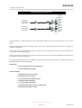
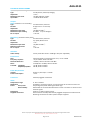
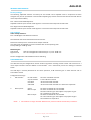
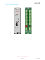
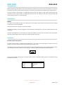
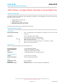
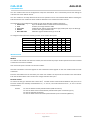
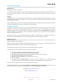
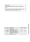
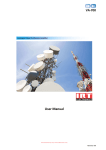
AAA-3131
Stereo Audio Distribution Amplifier
User Manual
IRT Electronics Pty Ltd | www.irtelectronics.com
Revision 03
AAA-3131
STEREO AUDIO DISTRIBUTION AMPLIFIER
Revision History:
Revision
00
01
Date
29/11/2006
05/01/2007
By
AL
AL
02
03
25/10/2010
25/05/2012
AL
AL
Change Description
Original Issue.
Overlay and link settings diagram added to
Configuration section.
Obsolescence of sub-board information noted.
Reformatted layout.
Applicable to:
S/N ≥ 0605001
S/N ≥ 0605001
S/N ≥ 0605001
S/N ≥ 0605001
IRT Electronics Pty Ltd | www.irtelectronics.com
Page 2 of 17
Revision 03
AAA-3131
USER MANUAL
Table of Contents:
Section
Page
Revision History
2
Operational Safety
4
General Description
5
Technical Specifications
6
Internal Adjustments
7
Configuration
7
AAA-3131 Overlay & Link Settings
8
Installation
9
Front and rear layouts
10
Sub-modules (NOTE: Obsolete – No Longer Available. Information for existing modules only)11
AAO-3130 FACTS Stereo Oscillator sub-module
11
General Description
11
Technical Specifications
11
Configuration
12
Installation
12
Operation
12
CAA-3130 Remote Mode & Phase Control sub-module
13
General Description
13
Technical Specifications
13
Configuration
14
Installation
14
CAA-3132 Dual Remote Control sub-module
15
General Description
15
Technical Specifications
15
Configuration
16
Installation
16
Maintenance & Storage
17
Warranty & Service
17
Equipment return
17
This instruction book applies to units later than S/N ≥ 0605001.
IRT Electronics Pty Ltd | www.irtelectronics.com
Page 3 of 17
Revision 03
AAA-3131
OPERATIONAL SAFETY
WARNING
Operation of electronic equipment involves the use of voltages and currents that
may be dangerous to human life. Note that under certain conditions dangerous
potentials may exist in some circuits when power controls are in the OFF position.
Maintenance personnel should observe all safety regulations.
Do not make any adjustments inside equipment with power ON unless proper
precautions are observed. All internal adjustments should only be made by suitably
qualified personnel. All operational adjustments are available externally without
the need for removing covers or use of extender cards.
IRT Electronics Pty Ltd | www.irtelectronics.com
Page 4 of 17
Revision 03
AAA-3131
GENERAL DESCRIPTION
BLOCK DIAGRAM AAA-3131 SIGNAL PATH
O/P’s
(Balanced)
O/P 1L
O/P 2L
O/P 3L
O/P 4L
O/P 5L
O/P 1R
O/P 2R
O/P 3R
O/P 4R
O/P 5R
Analogue
Audio I/P (L)
(Balanced)
Analogue
Audio I/P (R)
(Balanced)
The IRT AAA-3131 is a high performance audio distribution amplifier that can be used for either mono or stereo
signals.
Inputs and outputs are balanced connector types, which can be wired for unbalanced operation, if needed, for
duplicating applications.
Front panel access is provided for the gain adjustment of Left and Right channels from zero output to the
maximum of the selected gain range.
LED’s on the front panel indicate the presence of audio on each channel and balanced output bantam jacks are
provided for front panel monitoring.
The AAA-3131 is fabricated in IRT’s standard Eurocard format and may be housed in a variety of IRT Eurocard
frames alongside other standard modules.
Applications:
•
•
Stereo signal duplication and distribution.
Level matching and balancing.
Standard features:
•
•
•
•
•
•
•
Selectable stereo or mono mode.
Balanced inputs and outputs.
Front panel monitoring bantam jacks.
LED audio activity indicators.
Front panel gain adjustments.
Selectable gain ranges: +6 dB, +12 dB & +18 dB.
Maximum output level +24 dBu.
IRT Electronics Pty Ltd | www.irtelectronics.com
Page 5 of 17
Revision 03
AAA-3131
TECHNICAL SPECIFICATIONS
Inputs: Left/Mono and Right
Type
Impedance
Maximum input level
Input CMR
Tranformerless, balanced, bridging.
> 10 kΩ.
+24 dBu (6 dB gain mode).
> 55 dB 20 Hz to 20 kHz.
Outputs:
Main: (Located on rear assembly.)
Type
Number
Impedance
Maximum output level
Maximum output loading
DC on output
Transformerless, balanced.
10 (10 mono or 5 L and 5 R).
< 40 Ω.
+24 dBu into 600 Ω.
10 x 600 Ω or up to 26 High Z.
< ±20 mV.
Monitoring: (Located on front panel.)
Type
Transformerless, balanced.
Number
2 (L and R) Bantam Jack.
Impedance
< 70 Ω.
Maximum output level
+24 dBu into 600 Ω.
Minimum output load
1 kΩ.
DC on output
< ±20 mV.
Indicators:
Audio activity
2 front panel LED's set for +4 dBu @ 1 kHz (user adjustable).
Performance:
Gain
Frequency response
Harmonic distortion
Noise
Crosstalk Left/Right
Amplifier/Amplifier
Internally linked to a maximum gain of +6, +12 or +18 dB.
+ 0/- 0.3 dB for 20 Hz to 20 kHz.
< 0.005%, 20 Hz to 20 kHz at +20 dBm.
-110 dB, Ref. +24 dBm, 20 Hz to 20 kHz.
-75 dB, 20 Hz to 20 kHz.
-80 dB, 20 Hz to 20 kHz.
Power Requirements:
Voltage
Power consumption
28 Vac CT (14-0-14) or ± 16 Vdc.
< 5 VA.
Connectors:
Phoenix pluggable screw block.
Other:
Temperature range
Mechanical
Finish:
Front panel
Rear assembly
Dimensions
Supplied accessories
0 - 50° C ambient.
Suitable for mounting in IRT 19" rack chassis with all connections at the rear.
Grey background, black lettering & red IRT logo.
Detachable silk-screened PCB with direct mount connectors to Eurocard and
external signals.
6 HP x 3 U x 220 mm IRT Eurocard.
Rear connector assembly with Phoenix pluggable compression screw terminals.
Matching connectors for audio inputs & outputs supplied.
Due to our policy of continuing development, these specifications are subject to change without notice.
IRT Electronics Pty Ltd | www.irtelectronics.com
Page 6 of 17
Revision 03
AAA-3131
INTERNAL ADJUSTMENTS
Factory settings:
The following adjustable resistors are factory set and should not be adjusted unless a component has been
changed. They are not 'operational' controls. Before adjusting any of these controls allow time for the AAA-3131 to
reach temperature stability.
RV 1 "Left' Common Mode Rejection.
Adjusted to reduce input common mode signals to a minimum at the output of the AAA-3131.
RV 2 "Right' Common Mode Rejection.
Adjusted to reduce input common mode signals to a minimum at the output of the AAA-3131.
User settings:
Audio activity indicators:
RV 5 "Left & Right" Level detector threshold.
Note that RV5 sets the threshold level for both channels.
Detector threshold point is measured at the output of the DA.
This setting may be adjusted to a value consistent with normal operating level.
Factory setting is +4 dBu @ 1 kHz.
Maximum gain:
Left channel
Right channel
LK 8 set as designated on PCB overlay for +6, 12 or 18 dB max.
LK 7 set as designated on PCB overlay for +6, 12 or 18 dB max.
See also Configuration and Installation sections following.
CONFIGURATION
The AAA-3131 may be configured for several modes of operation including remote control and conversion to a
1
multi output oscillator with the addition of sub-modules . This is achieved by various link settings as outlined
below.
The AAA-3131 is normally delivered set for stereo operation, 6 dB maximum gain on both channels and no
1
sub-modules fitted.
Configuration Summary:
1
1.
Sub-modules :
2.
Stereo/mono:
No sub-module
Any sub-module
CAA-3130
CAA-3132
AAO-3130
LK 1 & LK 2 soldered on board.
Cut LK 1 & LK 2 on board.
Set to stereo mode as below.
Set to stereo mode as below.
Set to stereo mode as below. LK 7 & LK 8 are inoperative.
Stereo
Mono L Input
LK 3 & LK 6 installed. LK 4 not installed.
LK 3 & LK 4 installed. LK 6 not installed.
LK 8 sets maximum gain. Gain adjust is only by RV 3 L gain.
LK 7 and RV 4 are inoperative.
LK 4 & LK 6 installed. LK 3 not installed
LK 7 sets maximum gain. Gain adjust is only by RV 4 R gain.
LK 8 and RV 3 are inoperative.
Mono R Input
NOTE:
1 Sub-modules no longer available. Reference for previous modules sold already in existence.
IRT Electronics Pty Ltd | www.irtelectronics.com
Page 7 of 17
Revision 03
AAA-3131
AAA-3131 Overlay & Link Settings:
No sub module installed
Any sub module installed
LK1 and LK2 soldered on board.
Cut or remove LK1 and LK2.
Stereo mode
LK3 and LK6 installed. LK4 not installed.
Mono mode – Left input
LK3 and LK4 installed. LK6 not installed.
LK8 sets maximum gain. Gain is adjusted by RV3 Left Gain.
LK7 and RV4 are inoperative.
Mono mode – Right input
LK4 and LK6 installed. LK3 not installed.
LK7 sets maximum gain. Gain is adjusted by RV4 Right Gain.
LK8 and RV3 are inoperative.
LK9, LK10, LK11 and LK12
Bypasses output fan resistors.
Only used with special non-standard rear assembly – not supplied.
IRT Electronics Pty Ltd | www.irtelectronics.com
Page 8 of 17
Revision 03
AAA-3131
INSTALLATION
Pre-installation:
Handling:
This equipment may contain or be connected to static sensitive devices and proper static free handling precautions
should be observed.
Where individual circuit cards are stored, they should be placed in antistatic bags. Proper antistatic procedures
should be followed when inserting or removing cards from these bags.
Power:
AC mains supply:
Ensure that operating voltage of unit and local supply voltage match and that correct rating
fuse is installed for local supply.
DC supply:
Ensure that the correct polarity is observed and that DC supply voltage is maintained within
the operating range specified.
Earthing:
The earth path is dependent on the type of frame selected. In every case particular care should be taken to ensure
that the frame is connected to earth for safety reasons. See frame manual for details.
Signal earth: For safety reasons a connection is made between signal earth and chassis earth.
No attempt should be made to break this connection.
Installation in frame or chassis:
See details in separate manual for selected frame type.
Audio Connections:
For mono operation it is usual to connect the input audio cable to the Left input pins. For stereo connect the Left
input cable to the Left input and the Right input audio cable to the Right input.
The input and output connectors are 3 way balanced Phoenix connectors.
Where an unbalanced connection is required, the signal may be connected between either the + input and GND or
the – input and GND. On the input only the unused input pin should be connected directly to GND. Do not ground
the unused output pin, as this will damage the amplifier.
IRT Electronics Pty Ltd | www.irtelectronics.com
Page 9 of 17
Revision 03
AAA-3131
Front & rear panel connector diagrams:
IRT Electronics Pty Ltd | www.irtelectronics.com
Page 10 of 17
Revision 03
AAO-3130
AAA-3131
FACTS STEREO OSCILLATOR SUB-MODULE
(NOTE: Obsolete – No Longer Available. Information for existing modules only)
GENERAL DESCRIPTION
The AAO-3130 Four frequency switched stereo oscillator sub-module converts the supporting main module audio
distribution amplifier into a multi output reference stereo oscillator for test or alignment purposes. Right channel
can be set-up for either pulsed (interrupted every second) or continuous operation. This configuration conforms to
the recommended practice of FACTS (Federation of Australian Commercial Television Stations) for channel
identification.
Provision is made to remotely switch the frequency to a fixed 40 Hz, 400 Hz, 1 kHz or 10 kHz tone.
TECHNICAL SPECIFICATIONS
Control input:
Remote switch component
Connections
Pin 1
2
3
4
Single pole 4 position or equivalent (not supplied).
On rear assembly of main module.
4 pin female polarised IDC # 1300-104.
GND.
Relay 1 control.
Relay 2 control.
Relay 3 control (Oscillator On).
Performance:
(See main module specifications for other specifications)
Distortion
Frequency
< 0.01% at + 8 dBm.
Remote selectable to:
40 Hz, 400 Hz, 1 kHz or 10 kHz.
Power requirements:
Voltage
Power consumption
± 12 Vdc from main module.
See main module specifications.
Other:
Temperature range
Dimensions
Standard accessories
0 - 50° C ambient.
65 mm x 48 mm.
Matching connector for control input type: 1300-104.
Due to our policy of continuing development, these specifications are subject to change without notice.
IRT Electronics Pty Ltd | www.irtelectronics.com
Page 11 of 17
Revision 03
AAO-3130
AAA-3131
CONFIGURATION
Before installing the AAO-3130, on the audio distribution amplifier main board cut the on board links LK1 and LK2.
Ensure the main board is set for stereo operation as outlined in audio distribution amplifier main module section.
For pulsed tone on right channel, on AAO-3130 sub-board, set link settings to LK1 closed and LK2 open. For
continuous tone on right channel, on AAO-3130 sub-board, set link settings to LK1 open and LK2 closed. Left
channel always remains as a continuous tone.
INSTALLATION
Module
To install the sub-module onto the main module first ensure that the proper mode of operation has been selected
on both the main and sub-modules.
Then remove straps LK 1 and LK 2 on the main module.
Hold the sub-module so that the legends on the sub-board and the legends on the main module have the same
orientation.
Place the sub-module over the connector pins of the main module. The 16 pins fit into 16 holes in the sub-module.
Push the sub-board down until it rests on the orange insulation of the pins.
OPERATION
Remote control of frequency
To switch in the oscillator, relay RL3 must be switched on. This is done by connecting pins 1 and 4 on the 4 pin
header on the rear connector of the main module’s rear connector unit.
The frequency of the oscillator may be set using pins 2 and 3 connected to pin 1 of the remote connector on the
rear assembly of the main module. If no connection is made the oscillator will default to 400 Hz operation.
1 2 3 4
As the remote switches and wiring carry the full relay current it is important that the losses in the external wiring
be kept to a minimum.
Frequency
40 Hz
400 Hz
1 kHz
10 kHz
Connect to Pin 1 (GND)
2
Default N/C
2&3
3
IRT Electronics Pty Ltd | www.irtelectronics.com
Page 12 of 17
Revision 03
CAA-3130
AAA-3131
REMOTE MODE & PHASE CONTROL SUB-MODULE
(NOTE: Obsolete – No Longer Available. Information for existing modules only)
GENERAL DESCRIPTION
The CAA-3130 can remotely switch between mono and stereo modes or reverse the phase of the left channel in
stereo mode. Links on the board allow a choice of either a -3 dB or -6 dB mono mix (Only one mode is possible at
any time).
1.
2.
3.
4.
Normal stereo operation.
Reverse phase of left channel
Switch left channel input to mono output.
Mix left and right channels to mono output with selectable 3 dB or 6 dB cut in signal level.
TECHNICAL SPECIFICATIONS
Control input:
Remote gain component
Connections
Pin 1
2
3
4
(Not supplied).
On rear assembly of main module.
4 pin female polarised IDC # 1300-103-426.
GND.
Relay 1 control.
Relay 2 control.
Relay 3 control.
Performance:
(See main module specifications for other specifications).
Operation modes
Remote selectable:
(Only one mode is possible at any time)
Stereo (normal);
Invert left channel phase;
Mono output from left input;
Mix of stereo input to mono output.
Frequency Response
Distortion
Noise
Attenuation mono mix mode
+0 / -0.5 dB 20 Hz to 20 kHz.
< 0.1% at +20 dBm.
-100 dB wrt +24 dBm.
-3 dB or -6 dB selectable by links.
Power requirements:
Voltage
Power consumption
± 12 Vdc from main module.
See main module specifications.
Other:
Temperature range
Dimensions
Standard accessories
0 - 50° C ambient.
65 mm x 48 mm.
Matching connector for control input type: 1300-103-426.
Due to our policy of continuing development, these specifications are subject to change without notice.
IRT Electronics Pty Ltd | www.irtelectronics.com
Page 13 of 17
Revision 03
CAA-3130
AAA-3131
CONFIGURATION
The main module must first be configured to accept the sub-module. This is achieved by various link settings as
outlined in the main module manual.
The main module is normally delivered set for stereo operation and no sub-modules fitted.
Before installing the CAA-3130 check that the main module is set to stereo mode as detailed in main module
instruction manual.
INSTALLATION
Module
To install the sub-module onto the main module first ensure that the proper mode of operation has been selected
on both the main and sub-modules.
Then remove straps LK 1 and LK 2 on the main module.
Hold the sub-module so that the legends on the sub-board and the legends on the main module have the same
orientation.
Place the sub-module over the connector pins of the main module. The 16 pins fit into 16 holes in the sub-module.
Push the sub-board down until it rests on the orange insulation of the pins.
Remote control
CAA-3130 can be remotely switched to provide one of the following modes of operation (Only one mode is
possible at any time).
1. Normal stereo operation.
2. Reverse phase of left channel
3. Switch left channel input to mono output.
4. Mix left and right channels to mono output with selectable 3 dB or 6 dB cut in signal level.
To control the operation mode a switch should be wired between the pins marked Remote "1", "2", "3" and "4" on
the rear assembly.
Mode
Stereo Operation
Left Channel Phase Invert
Left Channel Mono
Right Channel Mono
Stereo to Mono Mix
Stereo to Mono Mix with ‘L’ Phase reversal
Connect to Pin 1 (GND)
No connection
2
3
4
3&4
2&3&4
IRT Electronics Pty Ltd | www.irtelectronics.com
Page 14 of 17
Revision 03
CAA-3132
AAA-3131
DUAL REMOTE CONTROL SUB-MODULE
(NOTE: Obsolete – No Longer Available. Information for existing modules only)
GENERAL DESCRIPTION
This plug-in option for selected IRT audio distribution amplifiers can be configured to provide any two of the
following modes of operation:
•
•
•
•
STEREO FADE over 75 dB range
STEREO TRIM of 6 dB
CROSS FADE over 75 dB or 6 dB range
MIX L+R & FADE both by up to 75 dB.
Only two modes of operation are possible at the same time.
TECHNICAL SPECIFICATIONS
Control input:
Remote gain component
Connections
Pin 1
2
3
4
10 kΩ potentiometer (Not supplied) One required for each of the two
functions.
On rear assembly of main module.
4 pin female polarised IDC # 1300-104-426.
CCW connection of the potentiometers (GND).
Rotor for first gain element.
CW connection of the potentiometers (1 kΩ in series with + 12 Vdc).
Rotor for second gain element.
Performance:
(See main module specifications for other specifications)
Frequency Response
Harmonic Distortion
Noise
Attenuation
+0 / -0.5 dB 20 Hz to 20 kHz.
< 0.1% 20 Hz to 20 kHz at +20 dBm.
-94 dB, Ref. +24 dBm 20 Hz to 20 kHz.
> 75 dB.( Measurement for stereo fade mode ).
Power requirements:
Voltage
Power consumption
± 12 Vdc from main module.
See main module specifications.
Other:
Temperature range
Dimensions
Standard accessories
0 - 50° C ambient.
65 mm x 48 mm.
Matching connector for control input type: 1300-104-426.
Due to our policy of continuing development, these specifications are subject to change without notice.
IRT Electronics Pty Ltd | www.irtelectronics.com
Page 15 of 17
Revision 03
CAA-3132
AAA-3131
CONFIGURATION
The main module must first be configured to accept the sub-module. This is achieved by various link settings as
outlined in the main module manual.
The main module is normally delivered set for stereo operation and no sub-modules fitted. Before installing the
CAA-3132 set the main module to stereo mode as detailed in main module instruction manual.
The CAA-3132 can be configured to provide any two of the following modes of operation: 1. Stereo Fade
Up to 75 dB attenuation on both channels simultaneously.
2. Trim
As above, but range limited to 6 dB.
3. Cross Fade
Fade down left, fade up right/ fade down right, fade up left. Up to 75 dB range.
4. Balance
As above but range limited to 6 dB.
5. Mix L+R & Fade
Add left to right and fade both by up to 75 dB.
To configure these options the following resistor values need to be in place:
Stereo Fade
Cross Fade
Audio Over
Mix L+R & Fade
Trim
Balance
RA
10k
10k
10k
6k8
10k
10k
RC
S/C
10k
10k
S/C
10k
10k
RD
O/C
O/C
33k
O/C
22k
22k
RE
O/C
O/C
O/C
6k8
O/C
O/C
RF
10k
10k
10k
10k
10k
22k
RH
S/C
10k
10k
10k
10k
10k
RJ
O/C
10k
10k
10k
22k
10k
RK
O/C
10k
10k
O/C
O/C
O/C
INSTALLATION
Module
To install the sub-module onto the main module, first ensure that the proper mode of operation has been selected
on both the main and sub-modules.
Then remove straps LK 1 and LK 2 on the main module.
Hold the sub-module so that the legends on the sub-board and the legends on the main module have the same
orientation.
Place the sub-module over the connector pins of the main module. The 16 pins fit into 16 holes in the sub-module.
Push the sub-board down until it rests on the orange insulation of the pins.
Remote control
To control the two gain elements two remote 10 kΩ variable resistor should be wired between the pins of J3 on
the main module rear assembly marked Remote “1”, “2” and “3”, for the first element and “1”, “4” and “3” for the
second element.
Connect
Pin 1 to the bottom of both potentiometers (CCW connection)
Pin 2 to the slider of the second element potentiometer (rotor connection) (Trim)
Pin 3 to the top (CW connection).
Pin 4 to the slider of the first element potentiometer (rotor connection) (Balance)
IRT Electronics Pty Ltd | www.irtelectronics.com
Page 16 of 17
Revision 03
AAA-3131
MAINTENANCE & STORAGE
Maintenance:
No regular maintenance is required.
Care however should be taken to ensure that all connectors are kept clean and free from contamination of any
kind. This is especially important in fibre optic equipment where cleanliness of optical connections is critical to
performance.
Storage:
If the equipment is not to be used for an extended period, it is recommended the whole unit be placed in a sealed
plastic bag to prevent dust contamination. In areas of high humidity a suitably sized bag of silica gel should be
included to deter corrosion.
Where individual circuit cards are stored, they should be placed in antistatic bags. Proper antistatic procedures
should be followed when inserting or removing cards from these bags.
WARRANTY & SERVICE
Equipment is covered by a limited warranty period of three years from date of first delivery unless contrary
conditions apply under a particular contract of supply. For situations when “No Fault Found” for repairs, a
minimum charge of 1 hour’s labour, at IRT’s current labour charge rate, will apply, whether the equipment is
within the warranty period or not.
Equipment warranty is limited to faults attributable to defects in original design or manufacture. Warranty on
components shall be extended by IRT only to the extent obtainable from the component supplier.
Equipment return:
Before arranging service, ensure that the fault is in the unit to be serviced and not in associated equipment. If
possible, confirm this by substitution.
Before returning equipment contact should be made with IRT or your local agent to determine whether the
equipment can be serviced in the field or should be returned for repair.
The equipment should be properly packed for return observing antistatic procedures.
The following information should accompany the unit to be returned:
1.
2.
3.
4.
5.
6.
7.
A fault report should be included indicating the nature of the fault
The operating conditions under which the fault initially occurred.
Any additional information, which may be of assistance in fault location and remedy.
A contact name and telephone and fax numbers.
Details of payment method for items not covered by warranty.
Full return address.
For situations when “No Fault Found” for repairs, a minimum charge of 1 hour’s labour will apply,
whether the equipment is within the warranty period or not. Contact IRT for current hourly rate.
Please note that all freight charges are the responsibility of the customer.
The equipment should be returned to the agent who originally supplied the equipment or, where this is not
possible, to IRT directly. Details of IRT’s direct address can be found at IRT Electronics’ website.
Web address: www.irtelectronics.com
Email: [email protected]
IRT Electronics Pty Ltd | www.irtelectronics.com
Page 17 of 17
Revision 03