1
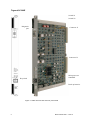
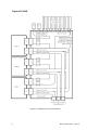
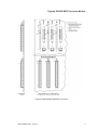
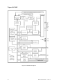
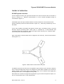
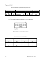
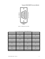
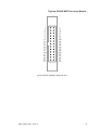
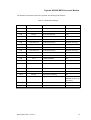
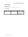
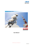
Triguard SC300E
MPP
Processor Module
(MPP)
Issue 6 October 2005
Three MPPs are fitted in the three right hand slots of the main chassis. They provide a central
processing facility for the Triguard SC300E system.
Operation of the system is software controlled by the Real Time Task Supervisor (RTTS) which
continuously executes the following functions:
•
Polling of inputs and outputs
•
Diagnostics to detect internal faults, power outages, voting agreement and the health
of the processor module microprocessor
•
Tracking of maintenance activities such as hot repair
•
Detection of latent faults in I/O modules
•
Execution of safety and control logic
•
Data acquisition and Sequence Of Events (SOE) for transmission to an operator
workstation
008-5100
Triguard SC300E
Switch S1
Switch S2
Diagnostic
port
Connector J1
Connector J2
Microprocessor
80486DX
Keyswitch
Back up batteries
Figure 1-1 MPP General view and front panel detail
2
MPP October 2005 – Issue 6
Triguard SC300E MPP Processor Module
ASSOCIATED DOCUMENTATION
Reference No
Title
008-5097
Chassis User Manual
008-5105
MBB Bus Extender Module User Manual
008-5115
TBA Bus Expansion Adaptor User Manual
008-5217
TBT Bus Terminator User Manual
SPECIFICATION
Model
MPP
Processor
Intel family
EPROM
1 Mbyte fitted
RAM
1 Mbyte fitted
RAM backup battery (optional)
Lithium battery, shelf life 8 to 10 years
(program holdup 6 months) (Spares available)
Inter processor communication
Serial high speed, read only
Diagnostic port
For factory testing purposes
4 position keyswitch
On Line, Program, Test, Reset
Indicators
Run, On Line, Program, Test, Health, I/O
Scan, Battery, Communications
Module power consumption
10W
Overall size (mm)
400(9U)H x 397L x 28W
Overall size (inches)
15.75H x 15.63L x 1.1W
MPP October 2005 – Issue 6
3
Triguard SC300E
Environmental specifications
The maximum ambient temperature measured at the hottest point within the Triguard system
shall not be greater than 60 degrees centigrade.
Temperature operating:
+5°C to 60°C
Temperature storage:
-25°C to +70°C
Humidity
5% to 95% non-condensing at ambient <40°C
EMC/RFI Immunity
Tested and certified to IEC 1131-Part 2 1994
Vibration/Shock
Tested and certified to IEC 1131-Part 2 1994
Certification:
General Certification: Ref. SC300E Product Guide (ref 008-5209)
TRANSPORT AND HANDLING
The processor module must be transported and stored in its original packing material which
should be retained for this purpose.
4
MPP October 2005 – Issue 6
Triguard SC300E MPP Processor Module
TECHNICAL DESCRIPTION
Physical
The MPP is a 9U high PCB with integral front panel. Some aspects of MPP operation are
determined by link settings.
External connections
Each module is plugged into the main chassis backplane bus system via two DIN41612
connectors J1 and J2 (Figure 1-1 ). Figure 2-1 shows the main chassis backplane bus
interconnections.
Diagnostic port
A 9 -pin D-type connector is provided on the front panel. The pinout is listed in Table 2-4. The
diagnostic port signals are also available at connector ‘g’ at the rear of the chassis backplane
(Table 2-5).
Chassis backplane
The signals passing through J2 are available at the rear of the main chassis backplane. The
rear backplane connectors are shown in Figure 2-2. For additional information, refer to the
Chassis User Manual (Ref 008-5097).
Connector J1 links the MPP to the I/O modules and is represented on the rear of the chassis
backplane by Area ‘d’. Area ‘d’ consists of extensions to the pins of the J1 mating connector
(96 pins in three columns a, b and c). Pins 07 to 10 of columns ‘b’ and ‘c’ arespecially
extended to enable the installation of the chassis address setting links (see Figure 2-5 ).
Column ‘b’ of connectors J2 links each MPP to the other MPPs via the Inter-Processor
Communications Bus.
Columns ‘a’ and ‘c’ of connectors J2 link each MPP to the expansion bus via rear backplane
connectors ‘e’.
MPP October 2005 – Issue 6
5
Triguard SC300E
Connector summary
Connector
Location
Type
J3 (diagnosic port)
MPP front panel (Figure 1-1)
9-pin D type socket female
J1 (I/O bus)
MPP rear edge (Figure 1-1)
96-pin DIN41612 type C male
J2 (expansion bus)
MPP rear edge (Figure 1-1)
96-pin DIN41612 type C male
e (expansion bus)
Rear of backplane (Figure2-1)
96-pin DIN41612 type C female
f (watchdog)
Rear of backplane
2-pin Combicon
g (diagnosic)
Rear of backplane
26-pin IDC socket
CONTROLS AND INDICATORS
Keyswitch
User control is by the four position front panel keyswitch.
The switch positions as follows:
ON LINE (1)
:
Position for normal operating mode
PROGRAM (2) :
TEST (3)
:
Position for loading application
Reserved for future use
RESET (4)
Holds microporcessor in reset mode
:
NOTE
The keyswitch can only be removed at the ON LINE (Position 1) setting.
6
MPP October 2005 – Issue 6
Triguard SC300E MPP Processor Module
LED indicators
The front panel LED’s illuminate to indicate the following conditions:
RUN (green):
MPP running (as indicated by microprocessor supervisory watchdog
output)
ON -LINE (yellow):
MPP on line
PROGRAM (yellow):
MPP in program mode
TEST (yellow):
Reserved for future use
HEALTH (green):
Microprocessor running (as indicated by microprocessor address
strobe monitoring circuit)
I/O SCAN (yellow):
Scan of I/O modules in progress
BATTERY (green):
Backup batteries (1 or 2) healthy
SIO COMMS (yellow):
Scan of serial I/O module in progress
MPP October 2005 – Issue 6
7
Triguard SC300E
Figure 2-1 Backplane bus interconnections
8
MPP October 2005 – Issue 6
Triguard SC300E MPP Processor Module
0
1
2
3
UNIT
ID
0
1
2
3
UNIT
ID
0
1
2
3
UNIT
ID
Figure 2-2 MPP Related backplane connectors
MPP October 2005 – Issue 6
9
Triguard SC300E
Figure 2-3 MPP Block diagram
10
MPP October 2005 – Issue 6
Triguard SC300E MPP Processor Module
THEORY OF OPERATION
SC300E system overview
A block diagram showing the signal flow between the main functional areas of the MPP is
shown in Figure 2-3 . External communication is via the chassis backplane wiring as
summarised in Figure 2-1 .
All SC300E input and output modules interface to three isolated I/O communications buses
(shown collectively as the Processor-I/O Bus in Figure 2-1 ), each being controlled by one of
the MPPs.
At the input modules, field signals are filtered and then split, via isolating circuitry, into three
identical, signal processing paths. Each path is controlled by a microcontroller that
coordinates signal path processing, testing and signal status reporting to its respective MPP,
via one of the I/O communications buses.
Each of the MPPs communicates with its neighbours via read only, serial communications
links (Figure 2-4 ).
Figure 2-4 Read serial communications only links
The MPPs synchronise at least once per application logic execution cycle, and each reads the
input, output and diagnostic status of its neighbours. Each MPP correlates and corrects its
memory image of the current state of the system using a 2-oo-3 software vote, logging any
discrepancies found in a local diagnostic history table.
Each MPP then executes its programmed application logic and sets its respective outputs, via
the I/O communications bus, to the required state.
MPP October 2005 – Issue 6
11
Triguard SC300E
Commanded output states are received by an output module’s microcontrollers which, using
2-oo-3 hardware voters, set the outputs to the field. Any discrepancy between a commanded
output state and the field output is detected by the microcontrollers and reported to the
appropriate MPP
OFFLINE/STARTUP DIAGNOSTICS
When a SC300E’s MPPs are first powered up, the following diagnostic routines are executed:
•
Initialisation of all SRAM
•
Memory configuration and size checks
•
RTTS and application logic copied to SRAM
•
All program checksums recalculated and checked
•
Configuration and checksums of neighbouring MPPs read and confirmed
•
Initialisation of synchronisation registers
•
Synchronisation registers of neighbouring processors read
A processor will then pause, waiting for the other two MPPs to complete their startup
diagnostics.
At powerup a SC300E system must have three healthy MPPs, otherwise the startup
diagnostics will prevent execution of the system application logic.
In the event of a processor failing a replacement MPP can be brought online using a warm start
command. Warm start commands can be issued from a TriBuild workstation or by use of an
application logic assigned input. A newly installed MPP will execute its startup diagnostics,
monitor the running MPP’s synchronisation registers and await a warm start command. At this
point checksums will be confirmed and the new MPP acquires I/O data tables from its
neighbours and commences execution of its application logic.
Online/continuous diagnostics
All memory reads and writes are automatically checked for errors by the MPPs' error checking
and correcting circuitry. Single memory errors are detected and corrected, all multiple errors
are flagged.
Software Implemented Fault Tolerant (SIFT) votes the data tables between the MPPs using a
majority vote algorithm, any errors being logged and corrected by the processors during their
'read neighbour's data' cycle.
Corrected memory errors are logged in diagnostic history tables. These tables can be
accessed by application logic functions and be used to generate system alarms. If multiple
errors are detected an MPP will be halted. An MPP’s I/O hot repair task regularly scans all
12
MPP October 2005 – Issue 6
Triguard SC300E MPP Processor Module
configured I/O slots to determine their status. All I/O modules have identity type registers
which allow the hot repair task to confirm the status of all fitted modules.
Circuit details
The block diagram (Figure 2-3 ) shows the main functional areas of the MPP circuit. Overall
control of the circuit is by the microprocessor. At a lower level, individual parts of the circuit are
controlled by Programmable logic (PALs) and peripheral devices.
Power supplies
The two 5.4Vdc supplies from the chassis PSUs are fused on entry to the MPP by 3A fuses
F1 and F2 respectively. Both supplies are then fed via three pairs of auctioneering diodes to
three 5V regulators. Each of the regulator outputs feeds a separate area of the MPP circuit.
The 12V outputs from the chassis PSUs are not used by the MPP.
System clock and supervisory circuits
The 32MHz system clock to the microprocessor is derived from a crystal oscillator. 16MHz
and 8MHz clock signals for use elsewhere in the system are obtained by dividing the system
clock. A microprocessor supervisory chip operates as follows:
•
Generates a reset signal to the microprocessor during a cold start
•
Monitors the charge state of the backup batteries and drives the Battery LED on the
front panel
•
Generates the basic watchdog signal. This signal controls the Run LED on the front
panel. A secondary watchdog circuit monitors the Address Strobe pulses from the
microprocessor. Its output controls the Health LED on the front panel.
Memory
The MPP has eight 32-pin DIL sockets used to mount the EPROMs which contain the
operating system RTTS.
Ten 32-pin sockets are provided for byte-wide SRAM in two banks of five. SRAM is supported by
one or two backup batteries in the absence of an external power supply.
Error detection and correction (EDC)
A 32-bit EDC processor detects and corrects single bit errors during reads from SRAM.
Dual port controller
The dual port controller controls accesses to SRAM by the Microprocessor and the
Communicator.
MPP October 2005 – Issue 6
13
Triguard SC300E
Configuration registers
The MPP is configured by setting 8-bit DIP switches S1 and S2 as listed in Table 2-3 and
Table 2-4.
Chassis address link settings
The correct link combination for the main chassis is shown in Figure 2-5 .
The physical locations of the chassis address setting links are indicated by small triangles in
columns ‘b’ and ‘c’ of areas ‘d’ in Table 2-2. On the chassis backplane and in the links are
identified as UNIT ID0 to UNIT ID3.
Figure 2-5 Main chassis link address settings
14
MPP October 2005 – Issue 6
Triguard SC300E MPP Processor Module
SUPPLEMENTARY INFORMATION
Table 2-2. Configuration register switch settings
Function Selected
Switch
Element
S1
Switch OFF
1
Cross load
No cross load (Default)
2
Cross load from 2
Cross load from 0 (Default)
3
Start RTTS (Default)
Start Monitor
4
Load from EPROM
No load (Default)
Baud rate (Default see Table
4)
Baud rate (Table 4)
8
Copy RTTS to RAM (Default)
Do not copy
1
No shadow
Shadow (Default)
2
Not used
Not used (Default)
3
Not used
Not used (Default)
4
No set
Set memory to CCH (Default)
Baud rate (Table 4)
Baud rate (Default see Table 4)
Not used
Not used (Default)
5 to 7
S2
Switch ON
5 to 7
8
Table 2-3. Configuration register switch settings for baud rate
Switch position
Baud rate
S 1-7
S 2-5
S 2-6
Baud rate
S 1-5
S- 1-6
OFF
OFF
9600
OFF
OFF
OFF
9600 (Default ON
OFF
OFF
9600
ON
OFF
OFF
9600
OFF
ON
OFF
9600
OFF
ON
OFF
9600
ON
ON
OFF
9600
ON
ON
OFF
9600
OFF
OFF
ON
4800
OFF
OFF
ON
4800
ON
OFF
ON
2400
ON
OFF
ON
2400
MPP October 2005 – Issue 6
957 Monitor
Switch position
S 2-7
CSI/O OFF
15
Triguard SC300E
Table 2-3. Configuration register switch settings for baud rate
Switch position
Baud rate
S 1-7
957 Monitor
Switch position
S 2-5
S 2-6
Baud rate
S 1-5
S- 1-6
S 2-7
CSI/O OFF
OFF
ON
ON
1200
OFF
ON
ON
1200
ON
ON
ON
19200 (Default)
ON
ON
ON
19200
NOTE
The diagram below (Figure 2-6 ) shows S1 in its default condition, i.e. elements
3, 5, 6, 7 and 8 all ON (CLOSED), and, elements 1, 2 and 4 all OFF (OPEN).
Figure 2-6 Switch S1 shown in Default condition
Table 2-4. Pinout for front panel diagnostic
16
Pin
Signal
Pin
Signal
1
Unused
6
DSR
2
RxD
7
RTS
3
TxD
8
CTS
4
DTR
9
Unused
5
0V
-
-
MPP October 2005 – Issue 6
Triguard SC300E MPP Processor Module
Figure 2-7 Diagnostic port pinouts
Table 2-5. Pinout for rear backplane diagnostic Port ‘g’
Pin
Signal
Pin
Signal
1
nc
2
nc
3
TxD
4
nc
5
RxD
6
nc
7
RTS
8
nc
9
CTS
10
nc
11
DSR
12
nc
13
0V
14
DTR
15
nc
16
nc
17
nc
18
nc
19
nc
20
nc
21
nc
22
nc
23
nc
24
nc
25
nc
26
nc
MPP October 2005 – Issue 6
17
Triguard SC300E
18
MPP October 2005 – Issue 6
Triguard SC300E MPP Processor Module
Figure 2-8 Rear backplane diagnostic port
MPP October 2005 – Issue 6
19
Triguard SC300E
SERVICING
SCOPE
The MPP is not field-repairable. Field servicing operations are confined to the routine
replacement of SRAM backup batteries, and the total replacement of faulty MPPs. Spare keys
are available.
Faulty MPPs should be returned for repair.
Before a spare MPP is fitted, ensure that both the positions of the links and the types of preprogrammed device are identical to those on the MPP that is being replaced.
While MPPs are out of the chassis it is good practice always to leave the front panel
keyswitch in the RESET position.
CAUTION 1
Do not attempt to repair a fault by replacing blown fuses F1 or F2. The fault that caused the
fuse(s) to fail will remain.
CAUTION 2
Spare MPPs should normally contain a full complement of pre-programmed devices. Should it
be necessary to transfer pre-programmed devices (EPROMs only) from a faulty MPP to a good
one, use the normal handling procedures for electrostatically sensitive devices and take
extreme care not to bend the IC pins.
DIAGNOSIS
A faulty MPP will be apparent by the abnormal state of its front panel LEDs. This may be
accompanied by audible alarms etc.
Note that in normal operation, the On Line, Run and Health LEDs will be on and the Test LED
will flicker at a rate determined by the preset ladder scan rate.
CONFIGURATION
Configuration is via links on the board.
Module Link settings
Link settings are given in Table 3-1
20
MPP October 2005 – Issue 6
Triguard SC300E MPP Processor Module
The locations of the links are shown in general view showing link locations.
Table 3-1. Module link settings
Fit Link
Across Pins
LK1
1&2
Data error monitoring
Yes
LK1
2&3
8MHz clock
No
LK2
Fit link
RTS-CTS loopback
Yes
LK3
1&2
5ms real time clock
No
LK3
2&3
10ms real time clock
Yes
LK4
1 & 2 and 3 & 4
Loopback operation
No (test use only)
LK5
1&2
4Mbit RAM devices
No
LK5
2&3
1Mbit Ram devices
Yes
LK6
1 & 2 and 3 & 4
Loopback operation
No (test use only)
LK7
Fit link
Write operations to flash memory
No
LK8
1&2
1Mbit or 2Mbit EPROMs
Yes
LK8
3&4
<1Mbit EPROMs
No
LK9
1 & 2 and 3 & 4
Loopback operation
No (test use only)
LK10
Fit link
Slow EPROM (<70ns)
Yes
LK11
Fit all links
Loopback operation
No (test use only)
LK12
Fit link
CPU self test
Yes
LK13
Fit link
Supervisory watchdog
No
LK14
Position 1
Logic 5V
Not applicable on
Modules at Rev 04
and above
LK14
Position 2
Battery backup enabled
No
LK14
Position 3
Battery backup disabled
Yes
MPP October 2005 – Issue 6
For Condition
Factory default
21
Triguard SC300E
REMOVAL AND REPLACEMENT
Removal
CAUTION
To prevent battery drain in storage, the backup batteries fitted to new modules have insulation
tabs fitted to their positive terminal. Remove these tabs before installing new modules. Ensure
link LK14 to Position 2 to enable battery backup.
The following applies to both faulty and non-faulty MPPs:
1.
Turn the front panel keyswitch to RESET.
2.
Remove the MPP.
Replacement and warm start with two MPPs already running
1.
Turn the new MPPs front panel keyswitch to RESET.
2.
Insert the new MPP.
3.
Turn the new MPPs front panel keyswitch to RUN. This will initiate a self test
procedure.
4.
Wait for the following LED states to stabilise on the MPP front panel:
RUN - on
ON LINE - on
PROGRAM - off
TEST - on
HEALTH - on
I/O SCAN - on
BATTERY - off
SI/O COMMS- off
5.
22
At a TriBuild workstation:
a)
From the TriBuild main menu select View.
b)
From the View drop-down menu select Diagnostics.
c)
From the Diagnostics drop-down menu select Warm Start Processor.
MPP October 2005 – Issue 6
Triguard SC300E MPP Processor Module
6.
The new MPP is on line when all three sets of MPP LEDs indicate the same.
MPP October 2005 – Issue 6
23
Triguard SC300E
BATTERY REPLACEMENT
Fresh batteries will sustain SRAM for a total of about six months (either in one long stretch, or
in several shorter stretches). The backup batteries should be replaced where it is known that
the total battery drain period is approaching six months or once every five years (whichever
occurs first).
If the SC300E System is Operating
1.
Remove one of the three MPPs.
2.
Remove and safely dispose of both batteries.
3.
Wait about 5 minutes for any capacitance in the system to discharge.
4.
Ensuring the correct polarity Figure 1-1 , fit the new batteries.
5.
Replace the MPP and perform a warm start.
6.
Repeat the above procedure for each of the remaining MPPs in turn.
If the SC300E System is Not Operating
If the system is not powered up, the data in SRAM is being supported by the backup batteries.
To preserve this data it is important not to remove both batteries at once.
If only one battery is fitted, install a new battery in the vacant slot before removing the old
battery.
24
MPP October 2005 – Issue 6
Triguard SC300E MPP Processor Module
SERVICE SUPPORT
SERVICE SUPPORT
Spare parts and technical advice can be obtained from your local area offices.
LIST OF SPARES
Circuit ref
Model No.
Details
B1, B2
AB002LGX
3V Lithium batteries (set of
two)
NOTE: A chassis containing
3MPPs would require three
sets of batteries
MPP October 2005 – Issue 6
25