1
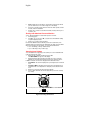
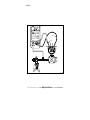
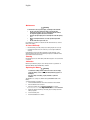
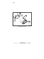
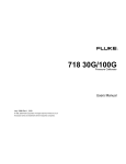
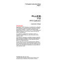
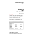
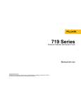
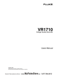
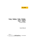
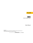
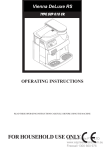
English ® 717 Series Pressure Calibrators Instruction Sheet Introduction The Fluke 717 Series Pressure Calibrators are compact, battery-powered, 5-digit instruments that perform the following calibration and measurement functions: • Calibrates P/I (pressure to current) transmitters • Measures pressure using a 1/8-inch NPT pressure fitting and an internal pressure sensor • Measures pressure via a Fluke 700 Series Pressure Module • Measures current up to 24 mA • Sources loop voltage (to 24 V dc) • Displays simultaneously pressure and current measurements • Calculates mA percentage in Percent Mode • Calculates mA error in Percent Error Mode The 717 Pressure Calibrators (hereafter, “the Calibrator”) include: • 717 1G • 717 1000G • 717 30G • 717 1500G • 717 100G • 717 3000G • 717 300G • 717 5000G • 717 500G Full Scale Pressure sensor is as listed in the “Specifications” section under “Pressure Specifications”. The Calibrator is an IEC 61010, CAT I 30 V, Pollution Degree 2 instrument. A CAT I instrument is designed to protect against transients from low-energy sources like, for example, electronic circuits or a copy machine. The Calibrator comes with a holster, an installed 9 V battery, a set of test leads and alligator clips, and a 14-language instruction sheet pack. If the Calibrator is damaged or something is missing, contact the place of purchase immediately. Shop for Fluke products online at: www. MyFlukeStore.ca 1.877.766.5412 PN 690013 March 1998, Rev. 2, 3/06 (English) 1998-2006 Fluke Corporation. All rights reserved. Printed in USA English Input Units The Calibrator measures and displays pressure sensor inputs in the units listed below: • Psi • inH2O@4°C • inH2O@20°C • cmH2O@4°C • cmH2O@20°C • bar • mbar • kPa • inHg@0°C • mmHg 2 • kg/cm If inappropriate units are selected, the output of Fluke 700P pressure modules can be too low to be displayed or can cause the Calibrator to display OL (overload). Refer to Table 1 for pressure unit and range compatibility. Table 1. Pressure Unit and Range Compatibility Units psi inH2O cmH2O bar mbar Range All Through 3000 psi Through 1000 psi 15 psi and above Through 1000 psi Units kPa inHg mmHg 2 kg/cm Range All All Through 3000 psi 15 psi and above Symbols Symbol Meaning + J W X ON / OFF button f Pressure T M $ P Double insulated Earth ground Caution: Important information. See instruction sheet Hazardous voltage, risk of electric shock Battery Canadian Standards Association Conforms to European Union requirements www.MyFlukeStore .ca 1.877.766.5412 Direct current Shop for Fluke products online at: F English Safety A "XW Warning" identifies conditions or actions that pose hazards to the user. A "W Caution" identifies conditions and hazards that may damage the Calibrator or equipment under test. XW Warnings To avoid electric shock, injury, or damage to the Calibrator: • Use the Calibrator only as described in this Instruction Sheet. • Using the Calibrator in a manner not specified by the manufacturer might impair the protection provided by the Calibrator. • Do not use the Calibrator to make measurements in a CAT II, CAT III, or CAT IV environment. CAT I equipment is designed to protect against transient from highvoltage, low-energy sources, such as electronic circuits or a copy machine. • Do not use the Calibrator around explosive gas, vapor, or dust. • Inspect the Calibrator before use. Do not use it if appears damaged. • Check the test leads for continuity, damaged insulation, or exposed metal. Replace damaged test leads. • Never apply more than 30 V between any two terminals, or between any terminal and earth ground. • Use the proper terminals, mode, and range for your measuring or sourcing application. • To prevent damage to the unit under test, put the Calibrator in the correct mode before connecting the test leads. • When making connections, connect the COM test lead before the live lead; when disconnecting, disconnect the live lead before the COM lead. • Never use the Calibrator with the case open. • Make sure the battery door is closed before you use the Calibrator. • Replace the battery as soon as the M (low battery) symbol appears to avoid false readings that can lead to electric shock. • Remove test leads from the Calibrator before opening the case or battery door. • To avoid a violent release of pressure in a pressurized system, shut off the valve and slowly bleed off the pressure before you attach or detach the pressure sensor or Pressure Module fitting to the pressure line. When servicing the Calibrator, use only specified replacement parts. W Caution When using pressure pressure modules, to avoid damage to the Calibrator module connections, follow all procedures in the pressure module instruction sheet. Shop for Fluke products online at: www.MyFlukeStore W Caution .ca 1.877.766.5412 When using pressure sensor connections, to avoid damage to the Calibrator or equipment to which it is attached: • To avoid overpressure damage, do not apply pressures that exceed ranges listed under “Pressure Specifications”. English • To avoid corrosion in the pressure sensor, use the Calibrator only with media compatible with glass, ceramic, silicon, RTV, nitrile (Buna -N) type 303 stainless steel, and nickel. • To avoid damaging the Calibrator, do not apply torque between the pressure fitting and the Calibrator case. See Figure 1 for the proper technique. Hold in fixed position qo001f.eps Figure 1. Proper Tightening Method Getting Acquainted Press O to turn the Calibrator ON and OFF. The Calibrator displays pressure and current measurements simultaneously. The upper part of the display shows the applied pressure. Press U to select a different unit. When you turn the Calibrator OFF, the next time you turn the Calibrator back ON it returns to the pressure unit you last used. The lower part of the display shows the current (up to 24 mA) applied to the current (mA) inputs. See Figure 2. Power Saver The Calibrator automatically turns off after 30 minutes of inactivity. To reduce this time or disable this feature: 1. With the Calibrator OFF, press O. 2. P.S. xx is displayed, where xx is the turn-off time in minutes. OFF means the power saver is disabled. 3. Press h (W) to decrease or a (Z) to increase the turn-off time. 4. To disable, press h until the display shows OFF. The Calibrator resumes normal operation after 2 seconds. Shop for Fluke products online at: www.MyFlukeStore .ca 1.877.766.5412 English 717 100G PRESSURE CALIBRATOR HOLD Pressure measurement Current mA measurement UNITS DAMP LOOP POWER On/Off Button MIN MAX ZERO mA MODE BAROMETRIC ADJ. SWITCH TEST HOLD Current input RANGE mA 30V MAX Pressure sensor input COM RANGE -12 TO 100 PSI -83 TO 690 kPa a mP MAX 200 PSI 1.4 I 69 mPa Pressure module input qo005f.eps Figure 2. The Pressure Calibrator (717 100G is Shown) Shop for Fluke products online at: www. MyFlukeStore.ca 1.877.766.5412 English Pushbutton Functions Button Function U Press to select a pressure unit. All units are available when the pressure sensor input is used. For higher pressure module inputs, inappropriate units are not available. Press O on while pressing U to source loop voltage. D ENTER Z Press to toggle pressure reading damping on and off. With damping on, the display does not update as quickly. Press to confirm selection of 0% and 100% output parameters. Press to zero the pressure display. (Vent pressure to atmosphere before pressing.) With an absolute pressure module, see instructions below. N Press to read the minimum pressure and current readings since power was turned on or the registers were cleared. Press again to read the maximum pressure and current readings since power was turned on. Press and hold to clear the MIN/MAX registers. S Press to perform switch test. Z a Press to toggle the mA display mode between mA, mA Percent, and mA Percent Error. Press h to freeze the display. h Y The gsymbol appears on the display. Press h again to resume normal operation. In ZERO mode, press to decrease barometric pressure. Switch Test To perform a switch test, do the following: Note This example uses a normally closed switch. The procedure is the same for an open switch but the display reads OPEN instead of CLOSE. 1. Connect the Calibrator mA and COM terminals to the switch using the pressure switch terminals and connect an external pump between the Calibrator and the pressure switch using a tee fitting. The polarity of the terminals does not matter. 2. Make sure the vent on the pump is open and zero the Calibrator if necessary. Close the vent after zeroing the Calibrator. 3. Press S to enter pressure switch test mode. The Calibrator will display CLOSE instead of a mA measurement. 4. Apply pressure with the pump slowly until the switch opens. Note Shop for Fluke products online at: www.MyFlukeStore .ca 1.877.766.5412 In the switch test mode, the display update rate is increased to help capture changing pressure inputs. Even with the enhanced sample rate, pressuring the device under test should be done slowly to ensure accurate readings. English 5. 6. 7. OPEN is displayed once the switch is open. Bleed the pump slowly until the pressure switch closes. The recall icon appears on the display. Press S to read the pressure values for when the switch opened, for when it closed, and for the deadband Hold S for 3 seconds to reset Switch Test mode; hold any other key for 3 seconds to exit. Zeroing with Absolute Pressure Modules To zero, adjust the Calibrator to read a known pressure as follows: 1. Press and hold Z. 2. Press Z (a) to increase or Y ( h)to decrease the Calibrator reading to equal the applied pressure. 3. Release Z to exit the zeroing procedure. For all but the 700PA3 module, the known pressure can be barometric, if it is accurately known. An accurate pressure standard can also apply a pressure within range for any absolute pressure module. To convert measurement units: • 1 bar = 750 mmHg (1 mmHg = 0.0013332 bar) • 1 psi = 2.036 inHg (1 inHg = 0.49115 psi). Sourcing Loop Voltage To use the Calibrator to supply loop power (24 V dc) to a current transmitter that is disconnected from the system: 1. With power off, hold down Uwhile pressing OON. The LOOP POWER icon appears on the display. 2. With the transmitter disconnected from normal loop power, connect the Calibrator in series with the instrument current loop as shown in Figure 3. In addition to mA, the current can be displayed in two alternative modes: • Percent Mode- The current is displayed as a percentage based on a 4-20 mA scale. • Percent Error Mode- Transmitter current output error is displayed. Error is calculated based on a configurable zero and span pressure and a 4-20 mA scale. 3. Measure loop current in the mA measurement display. 4. Press O OFF to deactivate the 24 V dc supply when you are done sourcing loop voltage. S I G N A L + – T E S T Shop for Fluke products online at: www. MyFlukeStore.ca 1.877.766.5412 qo007f.eps Figure 3. Sourcing Connections English Percent Error Setup Press and hold a. After 3 seconds the set icon and 0% appears on the lower display. Use Wand to adjust the 0% point for the Percent Error calculation, X then press D(ENTER) key to confirm selection. Press a. 100% is displayed on the lower display. Use Wand to adjust the 100% point for the Percent Error X calculation. Press D (ENTER) to confirm the selection and exit. Calibrating a P/I Transmitter To calibrate a P/I (pressure to current) transmitter: 1. Open the pump vent and zero the Calibrator before applying pressure. Repeat frequently to ensure accuracy. 2. Apply a pressure to the transmitter and measure the transmitter’s current loop output. OL (overload) is displayed at full scale. 3. Connect the Calibrator to the transmitter as shown in Figure 4 or Figure 5. The Calibrator recognizes only the pressure module if both types of connection are in place. Shop for Fluke products online at: www. MyFlukeStore.ca 1.877.766.5412 English 717 100G PRESSURE CALIBRATOR HOLD UNITS DAMP ENTER LOOP POWER MIN MAX ZERO Black mA MODE BAROMETRIC ADJ. SWITCH TEST HOLD Red RANGE 100psi 689kPa mA mA 30V MAX RANGE -12 O 100 PSI -83 O 690 kPa MAX a mP MAX 200 PSI 1.4 T mPa COM COM MAX T I 69 S I G N A L + – T E S T qo002f.eps Figure 4. Connecting to an Internal Pressure Sensor Shop for Fluke products online at: www. MyFlukeStore.ca 1.877.766.5412 English Calibrating a P/I Transmitter (Cont.) 717 100G + PRESSURE CALIBRATOR HOLD S I G N A L – T E S T UNITS DAMP ENTER LOOP POWER MIN MAX ZERO mA MODE BAROMETRIC ADJ. SWITCH TEST HOLD RANGE 100psi 689kPa Red Black mA 30V MAX COM RANGE -12 TO 100 PSI -83 TO 690 kPa a mP MAX 200 PSI 1.4 I 69 mPa Pressure Module Shop for Fluke products online at: www. MyFlukeStore.ca 1.877.766.5412 qo006f.eps Figure 5. Connecting to a Pressure Module English Maintenance XW Warning To avoid electric shock, personal injury, or damage to the Calibrator: • Do not service this product other than as described in this Instruction Sheet unless you are a qualified technician and have the required equipment and service information. • Remove any input signals prior to removing test leads and opening case. • When servicing the Calibrator, use only specified replacement parts. • Do not allow water to get in the case. For maintenance procedures not described in this Instruction Sheet, contact a Fluke Service Center. In Case of Difficulty • • Check the battery, test leads, and pressure tubing. Replace as necessary. Review this Instruction Sheet to make sure you are using the Calibrator correctly. If the Calibrator needs repair, and the Calibrator is under warranty, see the warranty statement for terms. If the warranty has lapsed, the Calibrator will be repaired and returned for a fixed fee. Cleaning Periodically wipe the case with a damp cloth and detergent; do not use abrasives or solvents. Calibration Calibrate your Calibrator yearly to ensure that it performs to specification. A Calibration Manual (Fluke PN 686540) is available. Replacing the Battery XW Warning To avoid false readings, which could lead to electric shock or injury, replace the battery as soon as M (low battery indicator) appears on the display. Use only a single 9 V battery, properly installed, to power the Calibrator. The Calibrator uses a single 9 V, alkaline battery (ANSI/NEDA 1604A or IEC 6LR61). To replace the battery (see Figure 5): 1. Turn the Calibrator OFF and remove the test leads from the terminals. 2. Remove Calibrator from its holster. 3. Remove the battery door on the back of the Calibrator as shown. for Fluke products from online at: MyFlukeStore .ca 1.877.766.5412 4. ShopLift the battery thewww. battery receptacle. 5. 6. 7. Attach the replacement battery to the leads, place the battery back in the battery receptacle. Secure the battery door. Return the Calibrator to its holster. English it07f.eps Figure 6. Battery Installation Shop for Fluke products online at: www. MyFlukeStore.ca 1.877.766.5412 English Replacement Parts and Accessories 1 2 3 15 4 5 6 7 8 10 9 11 13 12 14 16 qo004f.eps Item Part or Accessory No. Qty 2546258 1 A 717 case top for 300G and below 2546264 1 A 717 case top for 500G and above 2546993 1 B 717 1G Top Case Decal 2547000 1 B 717 30G Top Case Decal 2547017 1 B 717 100G Top Case Decal 2547021 1 B 717 300G Top Case Decal 2547039 1 B 717 500G Top Case Decal 2547042 1 B 717 1000G Top Case Decal 2547056 1 B 717 1500G Top Case Decal 2547063 1 B 717 3000G Top Case Decal 2547074 1 B 717 5000G Top Case Decal 2113087 1 C Keypad 687449 1 D Spacer for pressure input Shop products for online at: www. .ca 1.877.766.5412 146688 1 E for FlukeO-ring pressure input 1 F 9 V battery, ANSI / NEDA 1604A or IEC LR61 614487 2397526 1 G Case bottom MyFlukeStore Figure 7. Replacement Parts and Accessories English Item No. Qty H Case screw Part or Accessory 832246 3 I J K L M N O P P P P P P P P Q Battery door fasteners Non-skid foot Battery door Alligator clips Test lead set Holster, Yellow 717 30G LCD Bezel 717 100G LCD Bezel 717 300G LCD Bezel 717 500G LCD Bezel 717 1000G LCD Bezel 717 1500G LCD Bezel 717 3000G LCD Bezel 717 5000G LCD Bezel 717 1G LCD Bezel Instruction sheets (14) 948609 824466 609930 AC72 TL75 2074033 663997 1638728 2545073 2545099 2545105 2545110 2545122 2545131 2545064 690013 2 2 1 1 1 1 1 1 1 1 1 1 1 1 1 -- Figure 7. Replacement Parts and Accessories (cont.) Specifications Accuracy is specified for 1 year after calibration at operating temperatures of −10 °C to + 55 °C. Pressure Specifications Model Range SI Range Metric Max SI Max Metric 717-1G (-1 to 1) PSI (-7 to 7) kPa 5 PSI 34.5 kPa 717-30G (-12 to 30) PSI (-83 to 207) kPa 60 PSI 413 kPa 717-100G (-12 to 100) PSI (-83 to 690) kPa 200 PSI 1379 kPa or 1.4 mPa 717-300G (-12 to 300) PSI (-83 to 2068) kPa 375 PSI or 2.1 mPa 2586 kPa or 2.6 mPa 717-500G (0 to 500) PSI 3447 kPa or 3.4 mPa 1000 PSI 6895 kPa or 6.9 mPa 717-1000G (0-1000) PSI 6895 kPa or 6.9 mPa 2000 PSI 13790 kPa or 13.8 mPa 717-1500G (0-1500) PSI 10342 kPa or 10.3 mPa 3000 PSI 20684 kPa or 20.7 mPa Shop for Fluke products online at: www. MyFlukeStore.ca 1.877.766.5412 English Pressure Specifications (cont.) Model Range SI 717-3000G (0-3000) PSI Range Metric 20684 kpa or 20.7 mPa Max SI Max Metric 6000 PSI 41369 kPa or 41.4 mPa 34474 kPa or 68948 kPa 10000 PSI or 69 mPa 34.5 mPa Accuracy: Pressure Accuracy is +/- 0.05% of range Temperature coefficient: 0.01 % of range per °C for temperature ranges of between −10 °C to 18 °C and 28 °C to 55 °C. 717-5000G (0-5000) PSI Pressure Display, Pressure Module Input Range Resolution Accuracy Refer to the Instruction Sheet for the pressure module DC mA Input Range Resolution Accuracy, ± ( % of Reading + Counts) 24 mA 0.001 mA 0.015 + 2 Overload protection: Fuseless overvoltage protection Temperature coefficient: 0.005 % of range per °C for temperature ranges of between −10 °C to 18 °C and 28 °C to 55 °C. Loop Supply 24 V dc nominal General Specifications Maximum voltage applied between either an mA terminal and earth ground or between the mA terminals: 30 V Storage temperature: −40 °C to 60 °C Operating temperature: −10 °C to 55 °C Operating altitude: 3000 meters maximum Relative humidity: 95 % up to 30 °C; 75 % up to 40 °C; 45 % up to 50 °C; 35 % up to 55 °C Shop for Fluke products online at: www.MyFlukeStore .ca 1.877.766.5412 Vibration: Random 2 g, 5 Hz to 500 Hz, per MIL -PRF_28800F, Class 2 Shock: 1 meter drop, per IEC 61010-1 English Safety Compliance: IEC 61010-1 2nd Edition CAT I, 30 V; Pollution Degree 2 CSA C22.2 No. 1010.1; ANSI/ISA S82.02. Maximum Transient Overvoltage: 240 VAC for 10 Seconds. CE: Complies with EN 61326 Class A; EN61010-1 Protection Class: Class II, Double Insulated Power requirements: Single 9 V battery (ANSI/NEDA 1604A or IEC 6LR61) Size: 34.9 mm H x 87 mm W x 187 mm L (1.55 in H x 3.41 in W x 7.35 in L); With holster and Flex-Stand: 52 mm H x 98 mm W x 201 mm L (2.06 in H x 3.86 in W x 7.93 in L) Weight: 369 g (13 oz); With holster and Flex-Stand: 624 g (22 oz) Contacting Fluke To contact Fluke for product information, operating assistance, service, or to get the location of the nearest Fluke distributor or service center, call: USA: 1-888-99-FLUKE (1-888-993-5853) Canada: 1-800-36-FLUKE (1-800-363-5853) Europe: +31 402-675-200 Japan: +81-3-3434-0181 Singapore: +65-738-5655 Anywhere in the world: +1-425-446-5500 Or visit Fluke's web site at: www.fluke.com. Register your Calibrator at: http://register.fluke.com. Address correspondence to: Fluke Corporation Fluke Europe B.V. P.O. Box 9090, P.O. Box 1186, Everett, WA 98206-9090 5602 BD Eindhoven U.S.A. The Netherlands Limited Warranty & Limitation Of Liability This Fluke product will be free from defects in material and workmanship for 3 years from the date of purchase. This warranty does not cover fuses, disposable batteries, or damage from accident, neglect, misuse, alteration, contamination, or abnormal conditions of operation or handling. Resellers are not authorized to extend any other warranty on Fluke’s behalf. To obtain service during the warranty period, contact your nearest Fluke authorized service center to obtain return authorization information, then send the product to that Service Center with a description of the problem. THIS WARRANTY IS YOUR ONLY REMEDY. NO OTHER WARRANTIES, SUCH AS FITNESS FOR A for PARTICULAR ARE EXPRESSED OR IMPLIED. .ca FLUKE IS NOT LIABLE Shop Fluke productsPURPOSE, online at: www. 1.877.766.5412 FOR ANY SPECIAL, INDIRECT, INCIDENTAL OR CONSEQUENTIAL DAMAGES OR LOSSES, ARISING FROM ANY CAUSE OR THEORY. Since some states or countries do not allow the exclusion or limitation of an implied warranty or of incidental or consequential damages, this limitation of liability may not apply to you. MyFlukeStore 11/99