1
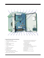
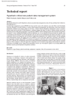
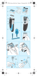
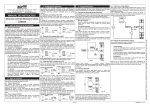
1ZSE 5492-154 en, Rev. 3, 2004-10-15 On-load tap-changers, type UZ User’s manual This document must not be copied without our written permission, and the contents thereof must not be imparted to a third party nor be used for any unauthorized purpose. Contravention will be prosecuted. Manufacturer’s declaration The manufacturer ABB Power Technologies AB, Components SE-771 80 LUDVIKA Sweden Hereby declares that The products On-load tap-changers types UZE and UZF with motor-drive mechanism type BUF 3 comply with the following requirements: By design, the machine, considered as component on a mineral oil filled power transformer, complies with the requirements of • Machinery Directive 89/392/EEC (amended 91/368/EEC and 93/44/EEC) and 93/68/EEC (marking) provided that the installation and the electrical connection be correctly realized by the manufacturer of the transformer (e.g. in compliance with our Installation Instructions) and • EMC Directive 89/336/EEC regarding the intrinsic characteristics to emission and immunity levels and • Low Voltage Directive 73/23/EEC (modified by Directive 93/68/EEC) concerning the built-in motor and apparatus in the control circuits. Certificate of Incorporation: The machines above must not be put into service until the machinery into which they have been incorporated have been declared in conformity with the Machinery Directive. Date 2003-01-15 Signed by ......................................................................... Folke Johansson Title Manager of Division for Tap-Changers Introduction The UZ range of on-load tap-changers manufactured by ABB has been developed over many years to provide maximum reliability. The simple and rugged design gives a service life equal to the service life of the transformer. Minimum maintenance is required for trouble-free operation. The only parts requiring maintenance are contacts that might need replacement during the service life, the insulating oil and the motor-drive mechanism. The design allows ready access to all parts, making inspection and maintenance quick and simple. The on-load tap-changer type UZE/UZF is placed in an oil-filled tank separated from the transformer tank. The motor-drive mechanism is attached to the side of the on-load tap-changer tank. WARNING and CAUTION WARNING A WARNING provides information which, if disregarded, could cause injury or death. CAUTION A CAUTION provides information which, if disregarded, could cause damage to the equipment. Safety precautions WARNING Personnel operating and inspecting the on-load tap-changer must have good knowledge about the apparatus and be aware of the risks pointed out in this manual. Personnel making electrical connections in the motor-drive mechanism have to be certified. WARNING The on-load tap-changer tank is filled with oil. The covers may be opened only by a specialist and after the transformer is taken out of service and the on-load tap-changer is drained. WARNING The cover for access to conductors on top of the UZF tank may be opened only after draining the transformer’s main tank. CAUTION After a pressure relay trip call a specialist. The on-load tap-changer must be drained, opened and carefully investigated before the transformer is re-energized. WARNING Small amounts of explosive gases will always come out from the breathing devices (dehydrating breather or one-way breather). Make sure that no open fire, hot surfaces or sparks occur in the immediate surroundings of the breathing devices. 4 Operation - - The position indicator shows the actual tap-position. The draghands show the max. and min. tap-position between which the on-load tap-changer has been working since last resetting. The tap-change in progress indicator shows RED during operation and WHITE when the on-load tap-changer is in position. For resetting of the emergency stop turn the knob clockwise. The LOCAL/REMOTE switch. In position LOCAL the on-load tap-changer can be operated by the RAISE/LOWER switch. In position LOCAL remote operation is rendered impossible. In position REMOTE the on-load tap-changer is operated from the control room or by a voltage regulator. Local operation is not possible in remote position. In case of a failure in power supply for the motor-drive mechanism it is possible to handcrank the on-load tap-changer. Put the handcrank on the shaft. Crank in the desired direction as per the information plate above the shaft. 20 turns for a complete operation. Continue cranking until the tap-change in progress indicator shows white. When the handcrank is inserted, all electrical operations are rendered impossible. WARNING The handcrank must not be inserted during electrical operation. WARNING If the on-load tap-changer is not in the exact position and the handcrank is pulled out, the motor-drive mechanism will start and go to the exact position if the power supply is on. - Thermostat for extra heater (option). We recommend a setting at +5 °C. - Hygrostat for extra heater (option). We recommend a setting at approximately 60 %. - Outlet (option) with earth fault protector. Normally the on-load tap-changer is controlled by a voltage regulator and no manual operation of the on-load tap-changer and the motor-drive mechanism is needed. WARNING If a failure in power supply occurs during operation, the operation will be completed when the power returns. Maintenance schedule Maintenance of the on-load tap-changer consists of three major steps: Inspection to be carried out by site personal once a year (see below) Overhaul to be carried out by a specialist at intervals stated on the rating plate Contact replacement to be carried out by a specialist. The need for contact replacement is decided during maintenance. CAUTION To maintain the high reliability of the on-load tap-changer it is important that the inspections and the overhauls be carried out at the interval stated on the rating plate. A specialist is a service engineer from ABB or an authorized person trained by ABB for maintenance work on UZ on-load tap-changers. 5 Inspection On the rating plate, ”inspection once a year” is recommended. This principally concerns the motordrive mechanism and refers to a visual inspection inside the BUF3 motor cabinet to check that nothing is loose, and that the heater is functioning. In the motor-drive mechanism a counter registers every tap-change operation. During inspection the counter is read. If possible, motor and counter are to be tested by operating one step and then back. If the on-load tap-changer has its own oil conservator, the breather and the oil level indicator on the oil conservator are to be checked. The inspection is to be carried out while the transformer is in service. CAUTION Approval should be given for inspection as well as for operating the on-load tap-changer. On the conservator the following are to be checked: Oil level Breather In the motor-drive mechanism the following items are to be checked: Motor and counter Emergency stop Heater Earth fault protector for the outlet (option) If the on-load tap-changer is equipped with an oil filter unit, the following item is to be checked: Pressure drop over the filter Required tools The following equipment is required for the inspection: Set of screwdrivers Pen and note pad Procedure WARNING Checking of the breather and the oil level must be carried out from ground level since the transformer is energized. 1 Checking of the breather If the oil conservator has a dehydrating breather, and more than half of the drying agent has changed colour, it must be dried or replaced. For drying see below. The drying agent normally starts to change colour from the bottom of the breather. If it has changed colour at the top, there is a leakage in the connections to the conservator. Locate the leakage and seal it. If the breather has an oil trap check the oil level. 6 WARNING The breathers and the tube from the conservator contains explosive gases. No open fire, hot surfaces or sparks may be present when removing the breather. To replace the drying agent, proceed as follows: Dismantle the breather and empty the agent . Replace with new drying agent. Alternatively, dry the old agent by placing it on a net and putting it in an oven, temperature approximately +100 oC (+212 oF), until it changes colour again. Fill the breather with drying agent. Clean the threads and apply sealing tape. Remount the breather. 2 Checking of the oil level At +20 °C (68 °F), oil is filled to the level where the pointer of the oil level indicator points half-way between MIN. and MAX. For other temperatures than +20 °C (68 °F), proceed as follows: - For every 10 °C (18 °F) increase in temperature, adjust the oil level upwards a tenth of the scale range of the oil level indicator. - For every 10 °C (18 °F) decrease in temperature, adjust the oil level downwards a tenth of the scale range of the oil level indicator. 3 Checking of the motor and the counter Open the motor-drive cabinet door and turn the selector-switch to the LOCAL position. Then turn the control switch to the RAISE (LOWER) position. Check that the motor works properly, the position indicator increases (decreases) one step, and the counter advances one step for each operation. Record the counter’s value. The counter shows the number of operations run by the on-load tap-changer (the overhaul schedule can be determined with the help of this information). Turn the control switch to the LOWER (RAISE) position. Check that the motor also works properly in that direction, the position indicator decreases (increases) one step and the counter advances one step more. Reset the draghands. 4 Checking of the emergency stop Give a RAISE or LOWER impulse and after about one second press the emergency stop. The operation should be interrupted. Reset the emergency stop by turning the knob clockwise and set the protective motorswitch to ON. The started operation should now be completed. Operate back to service position. 5 Checking of the earth fault protector (option) If the motor-drive mechanism is equipped with an outlet, the earth fault protector should be tested by pressing the test knob on the outlet. 6 Checking of the heater Disconnect the incoming auxiliary power. WARNING Before starting any work inside the motor-drive mechanism the auxiliary power must be switched off. N. B. The motor, contactors and heating element may be energized from separate sources. 7 Check by feeling with a finger on the protection plate that the heater has been functioning. Reconnect the incoming auxiliary power. Complete the inspection by turning the selector-switch to the REMOTE position and closing the cabinet door. 7 Checking of the oil filter unit (option) If the on-load tap-changer is equipped with an oil filter unit from ABB: Read the pressure gauge. Note the reading so the change from year to year can be seen. If the pressure is 2.0 bar or more, or close to 2.0 bar, the filter insert should be replaced. If moisture is suspected to have come into the on-load tap-changer compartment, the filter insert should be replaced. If a filter insert replacement is needed, call a specialist. Also check for leakages. All leakages should be repaired! 8 1 2 3 9 10 4 11 12 5 13 6 14 7 Layout of on-load tap-changer 1. 2. 3. 4. 5. Connection to oil conservator Cover for access to conductors, UZF only Attachment flange to transformer tank Terminals for conductors Pressure relay 8 6. Oil valve 7. On-load tap-changer tank 8. Lifting eye 9. Front cover 10. Moulding 11. Change-over selector 12. Fixed contact 13. Moving contact system 14. Transition resistor 1 11 2 12 3 13 4 14 5 15 6 16 7 17 18 8 19 9 20 10 21 22 Layout of motor-drive mechanism 1. Protective motor switch 2. Locking device prepared for padlock 3. Air vent 4. Draghand for min. position 5. Position indicator 6. Draghand for max. position 7. Counter 8. Lamp (25 W socket E14) 9. Shaft for handcrank 10. Emergency stop 11. Tap-change in progress indicator (Red = in progress, White = in position) 12. Heater 50 W (+ Option 250 W) 13. (Option) Outlet with earth fault protector 14. (Option) Thermostat or hygrostat for extra heater 250 W 15. Terminal blocks 16. RAISE/LOWER switch 17. LOCAL/REMOTE switch (Remote position for automatic operation) 18. (Option) Switch for extra heater 19. Serial number 20. Door-operated switch for lamp 21. Handcrank 22. Descriptions and circuit diagram 9 Notes 1ZSE 5492-154 en, Rev. 3, 2004-10-15 ABB Power Technologies AB Components Visiting address: Lyviksvägen 10 Postal address: SE-771 80 Ludvika, SWEDEN Tel.+46 240 78 20 00 Fax +46 240 121 57 E-mail: [email protected] www.abb.com/electricalcomponents