1
5012604300-AFE0
2011-02-15
Table of Content
01
02
03
04
05
06
07
08
09
10
11
12
13
14
Introduction .......................................................................................................................1-1
Installation .........................................................................................................................2-7
Wiring ……………………………………………………………………………………...……3-11
Main Circuit Terminal.......................................................................................................4-13
Control Terminal…………………………………………………………………………….…5-17
Optional Accessories.......................................................................................................6-21
Option Cards ...................................................................................................................7-41
Specifications ..................................................................................................................8-57
Digital Keypad .................................................................................................................9-59
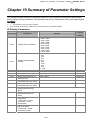
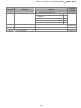
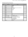
Summary of Parameter Settings ...................................................................................10-63
Description of Parameter Settings.................................................................................11-73
Warning Codes..............................................................................................................12-99
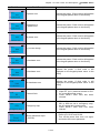
Fault Codes and Descriptions .....................................................................................13-103
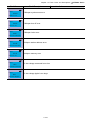
CANOpen Slave ........................................................................................................14-109
PLEASE READ THE FOLLOWING INFORMATION PRIOR TO INSTALLATION FOR SAFETY.
AC input power must be disconnected before any wiring or connection is made to the
AFE2000.
A charge may still remain in the DC-link capacitors with hazardous voltages after the power
DANGER
CAU TION
has been turned off. DO NOT touch the internal circuit and any other components before the
Power LED indicator is off.
There are highly sensitive MOS components on AFE2000 printed circuit boards. These
components are especially sensitive to static electricity. Please do not touch these
components or the circuit boards before taking anti-static measures. Never reassemble the
internal components or wires.
Ground AFE2000 using the ground terminal. The grounding method must comply with the
laws of the country.
Keep AFE2000 and the installation away from fire and inflammables.
Only the qualified personnel are allowed to install, wiring, and repair the drive.
A hazardous voltage may still remain in the AFE2000 main circuit terminals even when the
three-phase DC motor is at stop status.
If AFE2000 is not charged for more than 3 months, keep the ambient temperature lower than
30 °C. It should be avoided keeping AFE2000 in storage for over a year; it could cause
degradation of electrolytic capacitors.
NOTE
The content of this manual may be revised without prior notice. Please consult our distributors or download the recent
version at ( http://www.delta.com.tw/industrialautomation/ )
I
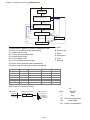
Chapter 1 Introduction AFE2000 Series
Chapter 1 Introduction
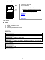
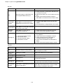
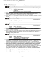
1.1 Receiving and Inspection
For usage safety of the AC motor drive, please check for the followings:
1.
Please inspect the unit after unpacking to assure it was not damaged during shipment.
2.
Make sure that the part number printed on the package corresponds with the part number indicated
on the nameplate.
3.
Make sure that the voltage for the wiring lie within the range as indicated on the nameplate.
4.
Please install the AC motor drive according to this manual.
5.
Before applying the power, please make sure that all the devices, including power, motor, control
board and digital keypad, are connected correctly.
6.
When wiring the AC motor drive, please make sure that the wiring of input terminals “R/L1, S/L2,
T/L3” and output terminals”U/T1, V/T2, W/T3” are correct to prevent drive damage.
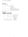
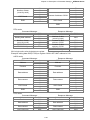
Nameplate
Mo del Name
Inpu t Volta ge/Current
MODEL: AFE075A23A
INPUT:
AC 3PH 170-260V50/60Hz 35A
Output Voltage /Cu rren t
OUTPUT:
DC 330V 33A
Encl osure (IPXX) Type
Firmware Versio n
Enclosure (IPXX) TYPE Des cription
Version:XX XX
Certifications
Serial Numbe r
075 AA2 37T001 0001
DELTA ELEC TRONIC S. INC .
MAD E IN XXXXXXX
1-1
Chapter 1 Introduction AFE2000 Series
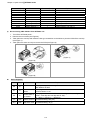
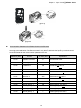
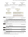
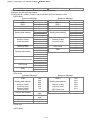
Model Name
AFE 075A 23 A
Versi on type
Inpu t vo ltage
23:2 30V 3-PHASE
43:4 60V 3-PHASE
Appli cabl e m otor ca paci ty
007 :1HP(0.75 kW)~ 7750: 100HP(7 5kW)
Refer to the spec ific ations for d etails
Series name(Active Front End Uni t)
Serial Number
075AA237 T 0 01 0001
Production numb er
Production we ek
Production year
0:20 10
Production factory
T: Tauyuan
W: Wujia n
S: Sha nghai
230 V 3-PHASE 10HP(7 .5kW)
Mo del numbe r
1-2
Chapter 1 Introduction AFE2000 Series
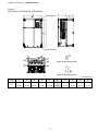
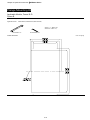
1.2 Dimensions
Frame B
AFE075A23A; AFE075A43A; AFE150A43A
See Detail A
See Detail B
Detail A (Mounting Hole)
Detail B (Mounting Hole)
Frame
B1
W
190.0
[7.48]
H
320.0
[12.60]
D
190.0
[7.48]
W1
173.0
[6.81]
H1
303.0
[11.93]
1-3
D1*
77.9
[3.07]
S1
8.5
[0.33]
Φ1
22.2
[0.87]
Unit:mm [inch]
Φ2
Φ3
34.0
28.0
[1.34]
[1.10]
D1*: Flange mounting
Chapter 1 Introduction AFE2000 Series
Frame C
AFE150A23A; AFE220A23A; AFE220A43A
See Detail A
See Detail B
Detail A (Mounting Hole)
Detail B (Mounting Hole)
Unit:mm [inch]
Frame
C1
W
H
D
W1
H1
D1*
S1
Φ1
Φ2
Φ3
250.0
400.0
210.0
231.0
381.0
92.9
8.5
22.2
34.0
50.0
[9.84]
[15.75]
[8.27]
[9.09]
[15.00]
[3.66]
[0.33]
[0.87]
[1.34]
[1.97]
D1*: Flange mounting
1-4
Chapter 1 Introduction AFE2000 Series
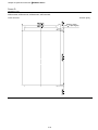
Frame D
D1: AFE370A23A; AFE370A43A; AFE450A43A; AFE750A43A;
D
W
W1
D1
D2
H2
H1
H
SEE DETAIL A
S2
SEE DETAIL B
S1
S1
DETAIL A
(MOUNTING HOLE)
DETAIL B
(MOUNTING HOLE)
Unit:mm[inch]
Frame
D1
W
H
D
W1
H1
H2
D1*
D2
S1
S2
330.0
550.0
275.0
285.0
525.0
492.0
107.2
16.0
11.0
18.0
[12.99]
[21.65]
[10.83]
[11.22]
[20.67]
[19.37]
[4.22]
[0.63]
[0.43]
[0.71]
D1*: Flange mounting
1-5
Chapter 1 Introduction AFE2000 Series
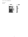
Digital Keypad
KPC-CE01
1-6
Chapter 2 Installation AFE2000 Series
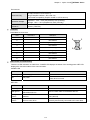
Chapter 2 Installation
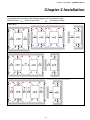
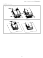
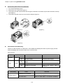
The appearances shown in the following figures are for reference only.
Airflow direction:
Single driv installation
(Frame B-D)
(Blue arrow) inflow
(Red arrow) outflow
Side-by-side installation (Frame B-C)
Multiple drives installation side-by-side (Frame B,C)
Multiple drives installation side-by-side (Frame D) Install a barrier between the drives
2-7
Chapter 2 Installation AFE2000 Series
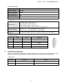
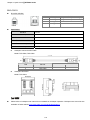
Multiple drives installation side-by-side in rows (Frame B,C) Ta: Frame B~D
For installation in rows, it is recommend to install a barrier between the drives. Adjust the size of the
barrier till the temperature measured at the fan’s inflow side is lower than the operation temperature.
Operation temperature is the defined as the temperature measured 50mm away from the fan’s inflow
side. (As shown in the figure below)
Minimum Mounting Clearances
Frame
A (mm)
B~C
60
D
100
B (mm)
30
50
C (mm)
10
-
D (mm)
0
0
Frame B AFE075A23A; AFE075A43A; AFE150A43A;
Frame C AFE150A23A; AFE220A23A; AFE220A43A;
Frame D AFE370A23A; AFE370A43A; AFE450A43A; AFE750A43A;
NOTE
1.
It is the minimum distance required for Frame B~D. If drives are installed closer than the minimum mounting clearance, the
fan would not be able to function properly.
2-8
Chapter 2 Installation AFE2000 Series
NOT E
※
The mounting clearances shown in the left figure are NOT for installing the
drive in a confined space (such as cabinet or electric box). When installing
in a confined space, besides the same minimum mounting clearances, it
needs to have the ventilation equipment or air conditioner to keep the
surrounding temperature lower than the operation temperature.
※
The following table shows heat dissipation and the required air
volume when installing a single drive in a confined space. When
installing multiple drives, the required air volume shall be multiplied
by the number the drives.
※
Refer to the chart (Air flow rate for cooling) for ventilation equipment
design and selection.
※
Refer to the chart (Power dissipation) for air conditioner design and
selection.
Air flow rate for cooling
Power Dissipation
Power Dissipation
Model No.
Loss External
External Internal Total External Internal Total
Internal Total
(Heat sink)
AFE075A23A
66
14
80
112
24
136
249
86
335
AFE150A23A
166
12
178
282
20
302
455
161
616
AFE220A23A
146
12
158
248
20
268
649
216
865
AFE370A23A
179
30
209
304
51
355
1091
220
1311
AFE075A43A
40
14
54
68
24
92
216
76
292
AFE150A43A
58
14
73
99
24
124
396
122
518
AFE220A43A
99
21
120
168
36
204
476
158
635
AFE370A43A
179
30
209
304
51
355
809
184
993
AFE450A43A
179
30
209
304
51
355
929
218
1147
AFE750A43A
186
30
216
316
51
367
1408
334
1742
※ The required airflow shown in chart is for installing single drive in a ※ The heat dissipation shown
confined space.
in the chart is for installing
single drive in a confined
※ When installing the multiple drives, the required air volume should
space.
be the required air volume for single drive X the number of the
drives.
※ When installing the multiple
drives, volume of heat
dissipation should be the
heat dissipated for single
drive X the number of the
drives.
※ Heat dissipation for each
model is calculated by rated
voltage, current and default
carrier.
Flow Rate (cfm)
Flow Rate (m3/hr)
2-9
Chapter 2 Installation AFE2000 Series
This page is intentionally left blank
2-10
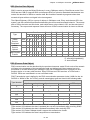
Chapter 3 WiringAFE2000 Series
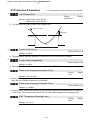
Chapter 3 Wiring
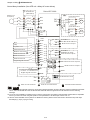
One-to-One Installation (One AFE unit + One AC motor drive)
*1
Mains Input
Frequency
AC Reacto r
(Stand ard)
U
Y
W
Z
AC Mo tor Drive
*2
X
V
Delta AFE 200 0
Mo tor
R/L1
S/L2
DC+
+1/DC+
DC-
-/DC-
IM/PM
T/L3
Th3
Option al
Th3 t1 s1 r1
r1/l1 *3
s1/l2
t1/l3
+24V
RA 1
COM
Run
RB 1
Mi 1
Stop
Multi-function output 1
RC 1
MI2
Sys tem erro r
Indi catio n:
DC Bus leve l attai ned
MI3
Reset after fault
React or ove r hea t
Mu lti-func tion 6
Mu lti-func tion 7
MI4
RA 2
MI5
RB 2
MI6
RC 2
Indi catio n:
AFE2000 is ready
Multi-function output 2
MI7
Mu lti-func tion 8
MI8
Digita l si gnal common
MO1 Mu lti-func tion output 3
DCM
MO2 Mu lti-func tion output 4
Powe r removal safe ty fu nction
for EN 95 4-1 and IEC/ EN 615 08
Digita l si gnal common
SG+
S1
MCM
DCM
8 1
8 1
I/O Exten sion Card
SG-
Ma in c ircuit termin al
.
Control circu it term inal
Shiel ded leads & Cabl e
NOTE
*1 The Delta AC reactor (optional accessory) comes with a thermal protection function. When the reactor’s temperature exceeds
120 ºC, the TH3 terminal will come ON and the AFE 2000 will receive a signal from the MI terminal to issue a warning
message.
*2 For one-to-many installation, installing a fuse on the AC motor drive’s input side is recommended. Please select a compatible
fuse for your AC motor drive using the equation: Fuse specification= AC rated input current/ 0.78*1.5
*3 If the AC reactor installed on the system is not Delta’s AC reactor, please connect the reactor’s terminal to the power input
terminal (R(L1), S(L2), T(L3)) for wiring.
3-11
Chapter 3 Wiring AFE2000 Series
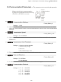
One-to-Many Installation (One AFE unit + Many AC motor drives)
*1
AC Reacto r
(Stand ard)
Delta AFE 2000
*2
Mains Input
Frequency
U
X
V
Y
W
Z
(1) AC Motor Drive
R/L1
DC+
DC-
S/L2
+1/DC+
-/DC-
T/L3
Motor
IM/P M
O pti on al
Th3
(2) AC Motor Drive
Th3 t1 s1 r1
+1/DC+
r1/l1 *3
-/DC-
s1/l2
t1/l3
RA 1
COM
RB 1
Mi 1
Stop
Indi catio n:
DC Bus level attai ned
Multi-function output 1
RC 1
MI2
System erro r
IM/P M
O pti on al
+24V
Run
Motor
MI3
Reset after fa ult
Reacto r ove r heat
Mu lti-function 6
Mu lti-function 7
MI4
RA 2
MI5
RB 2
MI6
RC 2
Indi catio n:
AFE2000 is ready
Multi-function output 2
MI7
Mu lti-function 8
MI8
Digital si gnal com mon
MO1 Mu lti-function o utput 3
DCM
MO2 Mu lti-function o utput 4
Powe r removal safe ty fun cti on
for EN 954 -1 and IEC/EN6 15 08
Digital si gnal common
SG+
S1
MCM
DCM
8 1
8 1
I/O Exten sion Card
SG-
Ma in circuit termin al
.
Control circu it term inal
Shiel ded leads & Cabl e
NOTE
*1 The Delta AC reactor (optional accessory) comes with a thermal protection function. When the reactor’s temperature exceeds
120 ºC, the TH3 terminal will come ON and the AFE 2000 will receive a signal from the MI terminal to issue a warning
message.
*2 For one-to-many installation, installing a fuse on the AC motor drive’s input side is recommended. Please select a compatible
fuse for your AC motor drive using the equation: Fuse specification= AC rated input current/ 0.78*1.5
*3 If the AC reactor installed on the system is not Delta’s AC reactor, please connect the reactor’s terminal to the power input
terminal (R(L1), S(L2), T(L3)) for wiring.
3-12
Chapter 4 Main Circuit TerminalsAFE2000 Series
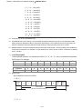
Chapter 4 Main Circuit Terminals
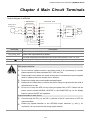
Terminal Diagram for AFE2000
AC Reacto r
(Standa rd )
V
Y
W
Z
r1/l1
X
s1 /l2
U
t1/l3
Mains Input
Frequency
Delta AFE 2000
Inverter
R(L1)
S(L2)
T(L3)
D+
+1/DC+
D-
-/DC-
Mo tor
IM/PM
Optiona l
r1/l1
s1 /l2
t1/l3
Terminals
Description
R(L1), S(L2), T(L3) AC line input terminals 3-phase
r1/l1, s1/l2, t1/l3
DC+, DC-
Phase lock input terminal 3-phase
AFE2000 output terminal connects to AC motor drive terminal +1/DC+ & -/DC-。
Protective grounding terminal, please ground according to the local regulations.
Main power terminal:
Do not connect 3-phase model to one-phase power. It is unnecessary to consider
phase-sequence for these terminals R/L1, S/L2 and T/L3.
Please make sure to fasten the screw of the main circuit terminals to prevent sparks
which is made by the loose screws due to vibration.
Please use voltage and current within the specification.
Please use the shield wire or tube for the power wiring and ground the two ends of
the shield wire or tube.
Do not run or stop the AFE unit by turning the power ON or OFF. Please use the
power control terminal MI-RUN, MI-STOP or the RUN/STOP key on the display
board to control the AFE unit operation.
Output terminals for main circuit:
Connects only the DC+(+1) and DC-(-) terminal of an AC motor drive to AFE unit
output terminals.
Please pay special attention to the AFE2000 output terminals (+) and (-) for
connection, do not connect to the wrong output terminal.
4-13
Chapter 4 Main Circuit TerminalsAFE2000 Series
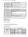
Main Circuit Terminals
Frame B
Main circuit terminals:
, DC+, DCR(L1), S(L2), T(L3),
Torque
(±10%)
M5
AFE075A23A
6 AWG (13.3mm2)
4 AWG
35kg-cm
AFE075A43A
8 AWG (8.4mm2)
(21.2mm2)
(30.4 lb-in.)
AFE150A43A
6 AWG (13.3mm2)
(3.434Nm)
UL installations must use 600V, 75℃ or 90℃ wire. Use copper wire
only.
Max. Wire
Gauge
Models
Min. Wire Gauge
DC+ & DC-: must use 1kV Wire.
NOTE
+
DC+
DC-
r1/l1
s1/l2
t1/l3
DETECTION
R/L1 S/L2 T/L3
POWER
Terminal r1/l1, s1/l2,
Wire Gauge:20AWG [0.5mm²] ~ 14 AWG [2.1mm²]
t1/l3:
Torque: 12 kg-cm [10.4 lb-in.] (1.18Nm) (±10%)
If additional terminal is needed when wiring, please refer to Figure 1 for
additional terminal dimension.
After crimping the wire to the ring lug please apply the UL approved R/C
(YDPU2) heat shrink tubing rate min 600Vac to the terminal. The insulation shall
be all over the live part. Please refer to Figure 2.
Detection wire
Figure 1
Figure 2
Figure 1
Figure 2
Power wire
4-14
Chapter 4 Main Circuit TerminalsAFE2000 Series
Main circuit terminals:
Frame C
R(L1), S(L2), T(L3),
, DC+, DC-
Torque
(±10%)
M8
AFE150A23A
1 AWG (42.4mm2)
2
1/0 AWG
80kg-cm
AFE220A23A
1/0 AWG (53.5mm )
(53.5mm2)
(69.4 lb-in.)
2
AFE220A43A
4 AWG (21.2mm )
(7.85Nm)
UL installations must use 600V, 75℃ or 90℃ wire. Use copper wire
only.
Max. Wire
Gauge
Models
Min. Wire Gauge
DC+ & DC-: must use 1kV Wire.
DC-
r1/l1
NOTE
+
DC+
s1/l2
DETECTION
t1/l3
R/L1
S/L2
POWER
T/L3
Terminal r1/l1, s1/l2,
Wire Gauge:20AWG [0.5mm²] ~ 14 AWG [2.1mm²]
t1/l3:
Torque: 12 kg-cm [10.4 lb-in.] (1.18Nm) (±10%)
When surrounding temperature exceeds 45℃, please use 600V,90℃ wire for
model AFE220A23A.
If additional terminal is needed when wiring, please refer to Figure 1 for
additional terminal dimension.
After crimping the wire to the ring lug please apply the UL approved R/C
(YDPU2) heat shrink tubing rate min 600Vac to the terminal. The insulation shall
be all over the live part. Please refer to Figure 2.
Detection wire
Figure 1
Figure 2
Figure 1
Figure 2
Power wire
4-15
Chapter 4 Main Circuit TerminalsAFE2000 Series
Frame D
Main circuit terminals:
R(L1), S(L2), T(L3)
, DC+, DC-,
Models
AFE370A23A
AFE370A43A
AFE450A43A
AFE750A43A
Max. Wire
Gauge
Min. Wire Gauge
300MCM
(152mm2)
250MCM (127mm2)
1/0 AWG (53.5mm2)
2/0 AWG (67.4mm2)
300MCM (152mm2)
Torque
(±10%)
M8
200kg-cm
(173 lb-in.)
(19.62Nm)
UL installations must use 600V, 75℃ or 90℃ wire. Use copper wire only.
DC+ & DC-: must use 1kV Wire.
NOTE
Terminal r1/l1, s1/l2, t1/l3:
Wire Gauge: 22AWG [0.3mm²] ~ 16 AWG [1.3mm²]
Torque: 5 kg-cm [4.3 lb-in.] (0.49 N.m)
If additional terminal is needed when wiring, please refer to Figure 1 for
additional terminal dimension.
After crimping the wire to the ring lug please apply the UL approved R/C
(YDPU2) heat shrink tubing rate min 600Vac to the terminal. The insulation shall
be all over the live part. Please refer to Figure 2.
Figure 1
4-16
Figure 2
Chapter 5 Control TerminalsAFE2000 Series
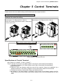
Chapter 5 Control Terminals
Please remove the cover before wiring multi-function input and output terminals.
The appearance of following figures are for reference only.
Removes the cover for wiring
Frame B
Frame C&D
Screw torque: 12~15Kg-cm [10.4~13lb-in.]
Screw torque: 12~15Kg-cm [10.4~13lb-in.]
Loosen the screws and press the tabs on both sides
to remove the cover.
Open
RC2 RB2 RA2 RC1 RB1 RA1
A
485
120
MO1 MO2
MCM
E24V DCM COM MI1 MI3 MI5 MI7
S1 E24V DCM COM MI2 MI4
B
MI6 MI8 SG+ SG-
Removable Terminal Block
Specifications of Control Terminal
Wire Gauge: 26~16AWG(0.1281-1.318mm2);
Torque: (A) 5kg-cm [4.31Ib-in.] (0.49Nm) (Refer to the Figure: Removable Terminal Block)
(B) 8kg-cm [6.94Ib-in.] (0.78Nm) (Refer to the Figure: Removable Terminal Block)
Wiring precautions:
Reserves 5mm and properly install the wire into the terminal; fasten the installation by a
slotted screwdriver. If the wire is stripped, sort the wire before install into the terminal.
Flathead screwdriver: blade width 3.5mm, tip thickness 0.6mm
As shown in the figure above, S1-DCM is short circuit as the factory setting; and for
E24V-COM is short circuit SINK mode (NPN), please refer to the following figures for more
detail.
5-17
Chapter 5 Control TerminalsAFE2000 Series
SINK(NPN)/SOURCE(PNP)Mode Switching Terminals.
1 Sink Mo de
with i nternal power (E 2 4Vdc)
2 Source Mo de
with i nternal power (E24Vd c)
MI2
MI2
~
MI1
~
MI1
MI8
MI8
DCM
E24V
COM
COM
DCM
inte rn al circui t
3 Sink Mo de
with e xternal power
4 Source Mo de
with e xternal power
MI2
MI2
~
MI1
~
MI1
MI8
MI8
+24V
+24V
COM
COM
DCM
external power +24V
Terminals
E24V
COM
MI1
~
MI8
DCM
MO1
inte rn al c ircui t
E24V
inte rn al circui t
Terminal Function
DCM
inte rn al c ircui t
external power +24V
Factory Setting (NPN mode)
Digital control signal common
+24V±5% 200mA
(Source)
Factory setting is short circuit status.
Digital control signal common (Sink)
Multi-function input 1~8
The parameters used to set multi-function inputs MI1~MI8
are Pr.02-01~Pr.02-08.
ON: the activation current is 6.5mA≧11Vdc
OFF: leakage current tolerance is 10μA≦11Vdc
Digital frequency signal common Common for multi-function input terminals.
Multi-function Output 1
(photocoupler)
The AFE2000 releases various monitor signals, such as
drive in operation, frequency attained and overload
indication, via transistor (open collector).
MO1
MO2
MCM
S1
DCM
Multi-function Output 2
MO2
(photocoupler)
MCM
Multi-function Output Common Max 48Vdc 50mA
(photocoupler)
The factory setting is short circuit.
Power removal safety function for EN954-1 and IEC/EN61508
5-18
Chapter 5 Control TerminalsAFE2000 Series
Terminals
Terminal Function
SG+
PIN 1,2,7,8 :Reserved
SG-
PIN 4: SG-
RA1
RB1
Factory Setting (NPN mode)
PIN 3, 6: GND
PIN 5: SG+
Multi-function relay output 1 (N.O.) Resistive Load:
5A(N.O.)/3A(N.C.) 250VAC
a
5A(N.O.)/3A(N.C.) 30VDC
Inductive Load (COS 0.4):
Multi-function relay output 1 (N.C.)
2.0A(N.O.)/1.2A(N.C.) 250VAC
2.0A(N.O.)/1.2A(N.C.) 30VDC
b
RC1
Multi-function relay common
RA2
Multi-function relay output 2 (N.O.) a
RB2
Multi-function relay output 2 (N.C.) b
RC2
Multi-function relay common
It is used to output each monitor signal, such as drive is
in operation, frequency attained or overload indication.
NOTE: Wire size of analog control signals: 18 AWG (0.75 mm2) with shielded wire
Digital inputs (FWD, REV, MI1~MI8, COM)
When using contacts or switches to control the digital inputs, please use high quality
components to avoid contact bounce.
Transistor outputs (MO1, MO2, MCM)
Make sure to connect the digital outputs to the right polarity.
When connecting a relay to the digital outputs, connect a surge absorber across the coil and
check the polarity.
Removing the Terminal Block
1. Loosen the screws by screwdriver. (As shown in the figure.)
2. Remove the control board by pulling it out in parallel direction for 6~8 cm (as indicated in the figure
below : arrow 1) then lift the control board (as indicated in the figure below: arrow 2).
5-19
Chapter 5 Control TerminalsAFE2000 Series
This page is intentionally left blank
5-20
Chapter 6 Optional Accessories|AFE2000 Series
Chapter 6 Optional Accessories
The accessories list in this chapter are sold separately and are available upon request. Please select
applicable accessories for your AFE2000 unit or contact local distributor for suggestion on applicable
model and specification. The optional accessories would significantly improves the AFE2000 efficiency.
¾
Non-fuse Circuit Breaker
¾
Fuse
¾
AC Reactor
¾
Zero Phase Reactor
¾
Digital Keypad
¾
Panel Mounting
¾
Conduit Box
¾
Fan Kit
¾
Flange Mounting Kit
6-21
Chapter 6 Optional Accessories|AFE2000 Series
Non-fuse Circuit Breaker
Comply with UL standard: Per UL 508, paragraph 45.8.4, part a,
The rated current of the breaker shall be 2~4 times of the maximum rated input current of the
AFE unit.
3-phase 230V
Recommended
Model
Current (A)
AFE075A23A
AFE150A23A
AFE220A23A
AFE370A23A
60
125
200
250
3-phase 460V
Recommended
Model
Current (A)
AFE075A43A
AFE150A43A
AFE220A43A
AFE370A43A
AFE450A43A
AFE750A43A
40
60
100
150
175
300
Fuse Specification Chart
Fuses with specification smaller than the following table indicates are allowed.
NOTE
1.
2.
3.
4.
5.
6.
Use Copper Conductors Only, 75ºC for all field-wiring terminals located within the motor circuit.
“The drive is suitable for use in a circuit capable of delivering not more than 5000 rms symmetrical amperes, (480 or 240) ac
maximum when used with listed Delta inverters.” Or equivalent.
“The drive must be installed in a Pollution 2 environment with clean air according to enclosure classification. Cooling air must
be clean, free from corrosive materials and electrically conductive dust.”
All rubber grommets located on conduit box shall be removed and replaced with conduit hubs in the end use installation.
“For installation in the United States, branch circuit protection must be provided in accordance with the National Electrical
Code (NEC) and any applicable local codes. To fulfill this requirement, use the UL classified fuses”
“For installation in Canada, branch circuit protection must be provided in accordance with Canadian Electrical Code and any
applicable provincial codes. To fulfill this requirement, use the UL classified fuses”
230VModel
Manufacturer
AFE075A23A
AFE150A23A
AFE220A23A
AFE370A23A
Cooper Bussmann Inc.
460V Model
Manufacturer
AFE075A43A
AFE150A43A
AFE220A43A
AFE370A43A
AFE450A43A
AFE750A43A
Cooper Bussmann Inc.
Class / Catalog No
Class _T / JJS-60
Class _T / JJS-125
Class _T / JJS-175
Class _T / JJS-250
Rating
600 Vac, 60A
600 Vac, 125A
600 Vac, 175A
600 Vac, 250A
Class / Catalog No
Class _T / JJS-35
Class _T / JJS-60
Class _T / JJS-90
Class _T / JJS-125
Class _T / JJS-175
Class _T / JJS-300
Rating
600 Vac, 35A
600 Vac, 60A
600 Vac, 90A
600 Vac, 125A
600 Vac, 175A
600 Vac, 300A
6-22
Chapter 6 Optional Accessories|AFE2000 Series
AC Reactor
Terminal Specifications
U
V
X
AF-RC075A2
AF-RC150A2
AF-RC220A2
AF-RC370A2
B
C
D
7.5
15
22
37
460 V
Frame KW
Reactor Model
AF-RC075A4
AF-RC150A4
AF-RC220A4
AF-RC370A4
AF-RC450A4
AF-RC750A4
B
C
D
7.5
15
22
37
45
75
Z
r1 s1 t1
TH3 TH3
230 V
Frame KW
Reactor Model
W
Y
Applicable
Rated
Torque: kg-cm / lb-in.. / Nm ±10%
Wieght
Inductance
Model
Current
mH
Mounting
TBLK-A, B
TBLK-C
Net(Kg)
AFE-_ _ _A23A
Arms
075
2.1
35
40.0 /46.1 /3.92 3.8 /4.4 /0.37 23.0/ 26.5/ 2.25
28
150
1.05
70
60.0 /69.2 /5.89 3.8 /4.4 /0.37 61.4/ 70.8/ 6.02
52
220
0.77
95
80.0 /92.2 /7.85 3.8 /4.4 /0.37 61.4/ 70.8/ 6.02
62
370
0.5
150 130.0 /149.9 /12.75 3.8 /4.4 /0.37 76.8/ 88.5/ 7.53
87
Applicable
Inductanc Rated
Torque: kg-cm / lb-in.. / Nm ±10%
Wieght
Model
e
Current
Mounting
TBLK-A, B
TBLK-C
Net(Kg)
AFE-_ _ _A43A
mH
Arms
075
7.32
20
40.0 /46.1 /3.92 3.8 /4.4 /0.37 23.0/ 26.5/ 2.25
28
150
4.18
35
60.0 /69.2 /5.89 3.8 /4.4 /0.37 23.0/ 26.5/ 2.25
52
220
2.92
50
80.0 /92.2 /7.85 3.8 /4.4 /0.37 61.4/ 70.8/ 6.02
62
370
1.96
75 130.0 /149.9 /12.75 3.8 /4.4 /0.37 76.8/ 88.5/ 7.53
87
450
1.54
95 160.0 /184.5 /15.70 3.8 /4.4 /0.37 76.8/ 88.5/ 7.53 105
750
0.92
160 220.0 /253.7 /21.58 3.8 /4.4 /0.37 76.8/ 88.5/ 7.53 137
Wiring Diagram
AC Reactor
U
Mains
X
V
Y
W
Z
r1/l1
s1 /l2
t1/l3
TH3
TH3
Delta AFE 200 0
R(L1) D+
S(L2)
DT(L3)
r1/l1
s1 /l2
t1/l3
MI5
DCM
6-23
AC Motor Drive
Motor
+1/DC+
U
-/DC-
V
W
IM/PM
Chapter 6 Optional Accessories|AFE2000 Series
Frame Structure
: Mounting holes
G
U
X
V
Y
W
s1
Z
t1
F
r1
*Suitable screw size: H
TBLK-B
TBLK-C
C MAX
TBLK-A
D
E
A MAX
B MAX
Model Specifications
Model
AF-RC075A2
AF-RC150A2
AF-RC220A2
AF-RC370A2
AF-RC150A4
AF-RC220A4
AF-RC370A4
AF-RC450A4
AF-RC750A4
AF-RC075A4
A
B
C
D
E
F
G
mm [inch] mm [inch] mm [inch] mm [inch] mm [inch] mm [inch] mm [inch]
305
[12.01]
355
[13.98]
355
[13.98]
385
[15.16]
355
[13.98]
355
[13.98]
385
[15.16]
385
[15.16]
420
[16.54]
305
[12.01]
159
[6.26]
180
[7.09]
200
[7.87]
210
[8.27]
180
[7.09]
200
[7.87]
210
[8.27]
230
[9.06]
240
[9.45]
159
[6.26]
280
[11.02]
328
[12.91]
328
[12.91]
385
[15.16]
328
[12.91]
328
[12.91]
385
[15.16]
385
[15.16]
440
[17.32]
280
[11.02]
150
[5.91]
200
[7.87]
200
[7.87]
200
[7.87]
200
[7.87]
200
[7.87]
200
[7.87]
200
[7.87]
250
[9.84]
150
[5.91]
6-24
125
[4.92]
139
[5.47]
159
[6.26]
168
[6.26]
139
[5.47]
159
[6.26]
168
[6.26]
188
[7.40]
200
[7.87]
125
[4.92]
22
[0.87]
26
[1.02]
26
[1.02]
25
[1.02]
26
[1.02]
26
[1.02]
25
[1.02]
25
[1.02]
25
[1.02]
22
[0.87]
11
[0.43]
11
[0.43]
11
[0.43]
13
[0.51]
11
[0.43]
11
[0.43]
13
[0.51]
13
[0.51]
13
[0.51]
11
[0.43]
H
Screw
Type
M10
M10
M10
M12
M10
M10
M12
M12
M12
M10
Chapter 6 Optional Accessories|AFE2000 Series
Zero Phase Reactor
RF220X00A
Cable
type
(Note)
Singlecore
Threecore
UNIT: mm(inch)
Recommended
Wire Size (mm2)
AWG mm2
Nominal
(mm2)
Qty.
≤10
≤5.3
≤5.5
1
≤2
≤33.6
≤38
4
≤12
≤3.3
≤3.5
1
≤1
≤42.4
≤50
4
Wiring
Method
Diagram
A
Diagram
B
Diagram
A
Diagram A
Please wind each wire around the core for 4 times.
The reactor must be placed at AFE2000 side as close
as possible.
Diagram
B
NOTE
600V insulated cable wire
1. The table above gives approximate wire size for
Diagram B
Please put wires through 4 cores in series without
winding.
the zero phase reactors but the selection is
ultimately governed by the type and the
diameter of the cable, i.e. the cable diameter
must small enough to go through the center of
the zero phase reactor.
2. When wiring, do not goes through the earth
core. It only needs to pass through the motor
cable or the power cable.
6-25
Chapter 6 Optional Accessories|AFE2000 Series
Digital Keypad
KPC-CC01
Frame size
Descriptions to the function key
Key
Description
START OPERATION
1. It is only valid when the source of operation command is from the keypad.
2. The RUN key starts AFE2000 to operate as the function setting and the RUN LED will be ON
3. It can be pressed again and again during stop.
STOP OPERATION (When Stop key is pressed, all operation will stop in all condition.) This key has the
highest priority in all condition.
1. When i STOP command is given, the AFE2000’s operation will stop under any condition.
2. The RESET key can be used to reset the drive when faults occur. If the RESET key is not responsing,
check MENU Æ Fault Records search for the most recent fault.
OPERATION DIRECTION (This function will be available soon)
ENTER
Press ENTER and go to the next level. If it is the last level then press ENTERnter to execute the
command.
ESC
Press ESC to return to the last page. If there is a sub-menu, press ESC will return to the
previous category.
MENU, press MENU key at any time would return to the main menu.
List of function:
KPC-CE01does not support function 4~112.
KPC-CC01does not support function 4, 5 and 7.
1. Detail Parameter
5. Copy PLC
2. Copy Parameter
6. Fault Record
3. Keypad Locked
7. Simple/ Quick Setting
4. PLC Function
8. Display Setting
9.
10.
11.
12.
Time Setting
Language Setting
Startup Menu Setting
Main Page Setting
1. “up”, “down”, “left” and “right”.
2. When setting the number, use “left” and “right” key to increase and decrease the value.
3. When selecting the options, use “up” and “down” key to move the selection.
Function key (This function will be available soon.)
6-26
Chapter 6 Optional Accessories|AFE2000 Series
(This function will be available soon.)
(This function will be available soon.)
6-27
Chapter 6 Optional Accessories|AFE2000 Series
面 Panel Mounting (MKC-KPPK)
Panel Mounting (MKC-KPPK)
For MKC-KPPK model, user can choose wall mounting or embedded mounting. The protection level is IP56.
Applicable to the digital keypads (KPC-CC01 & KPC-CE01).
Wall Mounting
accessories*1
Screw *4 ~M4*p 0.7 *L8mm
Torque: 10-12kg-cm (8.7-10.4lb-in.)
Panel cutout dimension
Unit: mm [inch]
Embedded Mounting
accessories*2
Screw *4 ~M4*p 0.7 *L8mm
Torque: 10-12kg-cm (8.7-10.4lb-in.)
Panel cutout dimension
Unit: mm [inch]
Normal cutout dimension
Panel
1.2mm
1.6mm
2.0mm
thickness
A
66.4 [2.614]
B
110.2 [4.339] 111.3 [4.382] 112.5 [4.429]
*Deviation: ±0.15mm /±0.0059inch
Cutout dimension (Waterproof level: IP56)
Panel
1.6mm
2.0mm
1.2mm
thickness
A
66.4 [2.614]
B
110.8 [4.362]
*Deviation: ±0.15mm /±0.0059inch
6-28
Chapter 6 Optional Accessories|AFE2000 Series
6-29
Chapter 6 Optional Accessories|AFE2000 Series
Conduit Box Kit
Appearance
Frame D
Applicable modle
AFE370A23A; AFE370A43A; AFE450A43A; AFE750A43A;
Model number『MKC-DN1CB』
ITEM
Description
1 Screw M5*0.8*10L
2 Rubber 28
3 Rubber 44
4 Rubber 88
5 Conduit box cover
6 Conduit box base
Qty.
4
2
2
2
1
1
Installation
Frame D
1.
Loosen the cover screws and press the tabs on each side of the cover to remove the cover, as shown in the
following figure. Screw torque: 10~12kg-cm (8.66~10.39Ib-in)
2.
Remove the 5 screws shown in the following figure. Screw torque: 24~26kg-cm (20.8~22.6Ib-in).
6-30
Chapter 6 Optional Accessories|AFE2000 Series
3.
Install the conduit box by fasten the 5 screws shown in the following figure.
Screw torque: 24~26kg-cm (20.8~22.6Ib-in).
4.
Fasten the 4 screws shown in the following figure. Screw torque: 10~12kg-cm (8.66~10.39Ib-in).
6-31
Chapter 6 Optional Accessories|AFE2000 Series
Fan Kit
Frames
Frame B
Frame B
Frame B
Applicable mode: AFE075A43A ; AFE075A23A; Applicable mode: AFE150A43A;
Fan Model『MKC-BFKM1』
Frame C
Fan Model 『MKC-BFKM2』
Applicable mode: AFE075A23A; AFE075A43A;
AFE150A43A;
Fan Model 『MKC-BFKB』
Frame D
Applicable mode: AFE150A23A; AFE220A23A; Applicable mode: AFE370A23A; AFE370A43A; AFE450A43A; AFE750A43A;
AFE220A43A;
Fan Model 『MKC-CFKB1』
Fan Model 『MKC-DFKM』
Fan Model 『MKC-DFKB』
Fan Removal
Frame B
Applicable mode: AFE075A43A;AFE075A23A; AFE150A43A
1. Press the tab on both side of the fan to successfully remove 2. Disconnect the power terminal before removing the fan.
the fan.
Frame B&C
Applicable model
AFE075A23A; AFE075A43A; AFE150A43A; AFE150A23A;
AFE220A23A; AFE220A43A
Disconnect the power terminal and use a slotted screwdriver to
remove the fan cover.
6-32
Chapter 6 Optional Accessories|AFE2000 Series
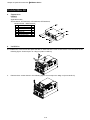
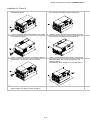
Frame D
Applicable model
AFE370A23A; AFE370A43A; AFE450A43A; AFE750A43A;
1.
(Figure 1) Loosen screw 1 and screw 2, press the on the
right and the left to remove the cover, follow the direction
the arrows indicate. Press on top of digital keypad
KPC-CE01 to properly remove the keypad. Screw torque:
10~12kg-cm (8.6~10.4in-lbf).
2.
(Figure 2) Loosen screw 3 and screw 4, press the tab on
the right and the left to remove the cover. Screw torque:
6~8kg-cm (5.2~6.9in-lbf).
3
4
1
2
Figure 2
Figure 1
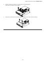
3.
(Figure 3) Loosen screw 5 and disconnect the fan power.
Screw torque: 10~12kg-cm (8.6~10.4in-lbf).
4.
5.
(Figure 4) Loosen the screws. Screw torque: 24~26kg-cm
(20.8~25.6in-lbf).
Disconnect fan power and pull out the fan. (As shown in the
larger picture)
5
1
2
3
4
Figure 3
Figure 4
6-33
Chapter 6 Optional Accessories|AFE2000 Series
Flange Mounting Kit
Applicable Models, Frame B~D
Frame B
『MKC-BFM』
Applicable model
AFE075A23A; AFE075A43A; AFE150A43A;
Screw 1 *4 ~ M8*P 1.25;
Screw 2*6 ~ M6*P 1.0;
Accessories 1*2
Accessories
2*2
Cutout dimension
Unit: mm [inch]
6-34
Chapter 6 Optional Accessories|AFE2000 Series
『MKC-BFM』Installation
1.
Install accessory 1& 2 by fastening 4 of the screw 1(M8). Screw torque: 40~45kg-cm (34.7~39.0Ib-in).
(As shown in the following figure)
2.
Plate installation, place 6 of the screw 2 (M6) through accessory 1&2 and the plate then fasten the screws.
Screw torque: 25~30kg-cm (5.21~6.94Ib-in). (As shown in the following figure)』
6-35
Chapter 6 Optional Accessories|AFE2000 Series
Frame C
『MKC-CFM』
Applicable model
AFE150A23A; AFE220A23A; AFE220A43A;
Screw 1*4 ~ M8*P 1.25;
Screw 2*8 ~ M6*P 1.0;
Accessories 1*2
Accessories 2*2
Cutout dimension
Unit:mm [inch]
6-36
Chapter 6 Optional Accessories|AFE2000 Series
Installation『MKC-CFM』
1.
Install accessory 1& 2 by fastening 4 of the screw 1(M8). Screw torque: 50~55kg-cm (43.4~47.7Ib-in).
(As shown in the following figure)
2.
Plate installation, place 8 of the screw 2 (M6) through accessories 1&2 and the plate then fasten the screws.
Screw torque: 25~30kg-cm (5.21~6.94Ib-in). (As shown in the following figure)
6-37
Chapter 6 Optional Accessories|AFE2000 Series
Frame D
Applicable model
AFE370A23A; AFE370A43A; AFE450A43A; AFE750A43A;
Unit:mm [inch]
Cutout dimension
M10*P1.5(4X)
OR 11.0[0.43](4X)
6-38
Chapter 6 Optional Accessories|AFE2000 Series
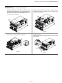
Installation for Frame D
1. Loosen 8 screws and remove Fixture 2 (as shown in 5. Fasten 4 screws (as shown in the following figure).
Screw torque: 24~26kg-cm (20.8~22.6Ib-in).
the following figure).
2. Loosen 10 screws and remove Fixture 1 (as shown
in the following figure).
6. Fasten 5 screws (as shown in the following figure).
Screw torque: 24~26kg-cm (20.8~22.6Ib-in).
3. Fasten 4 screws (as shown in the following figure). 7.
Screw torque: 30~32kg-cm (26.0~27.8Ib-in).
; Fasten 5 screws (as shown in the following figure).
Screw torque: 30~32kg-cm (26.0~27.8Ib-in).
6-39
Place 4 screws (M10) through Fixture 1&2 and the
plate then fasten the screws. (as shown in the
following figure)
Screw torque: 200~240kg-cm (173.6~208.3Ib-in).
Chapter 6 Optional Accessories|AFE2000 Series
This page is intentionally left blank
6-40
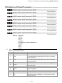
Chapter 7 Option CardsAFE2000 Series
Chapter 7 Option Cards
The option cards listed in this chapter are sold separately and are available upon request. Please select
applicable cards for your AFE2000 unit or contact local distributor for suggestion on applicable model and
specification. The optional accessories would significantly improves the AFE2000 performance.
Please removes the digital keypad and the top cover before installation and install the option card
according to the follows the following instruction or damage may result.
Remove key cover
Frame B&C
Screw Torque: 8~10Kg-cm [6.9~8.7lb-in.]
Frame D
Screw Torque: 8~10Kg-cm [6.9~8.7lb-in.]
7-41
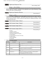
Chapter 7 Option CardsAFE2000 Series
1 RJ45(Socket) for digital keypad
1
Slot 3
KPC-CC01; KPC-CE01
Please refer to CH09 Digital Keypad for more details on
KPC-CE01
2
Slot 2 Slot 1
Please refer to CH09 Digital Keypad for more details on
optional accessory RJ45 extension cable.
2 Communication extension cards(Slot 1)
CMC-MOD01;
CMC-PD01;
CMC-DN01;
CMC-EIP01;
EMC-COP01;
CMC-MOD01
Features
1.
2.
3.
4.
5.
6.
Supports Modbus TCP protocol
MDI/MDI-X auto-detect
Baud rate: 10/100Mbps auto-detect
E-mail alarm
AC motor drive keypad/Ethernet configuration
Virtual serial port
Specifications
Network Interface
Interface
RJ-45 with Auto MDI/MDIX
Number of ports
1 Port
Transmission method
IEEE 802.3, IEEE 802.3u
Transmission cable
Category 5e shielding 100M
Transmission speed
10/100 Mbps Auto-Detect
Network protocol
ICMP, IP, TCP, UDP, DHCP, SMTP, MODBUS OVER TCP/IP, Delta Configuration
Electrical Specification
Power supply voltage
5VDC(suppliled by AFE2000)
Insulation voltage
2KV
Power consumption
0.8W
Weight
25g
7-42
Chapter 7 Option CardsAFE2000 Series
Environment
Noise immunity
ESD(IEC 61800-5-1,IEC 6100-4-2)
EFT(IEC 61800-5-1,IEC 6100-4-4)
Surge Teat(IEC 61800-5-1,IEC 6100-4-5)
Conducted Susceptibility Test(IEC 61800-5-1,IEC 6100-4-6)
Operation/storage
Operation: -10°C ~ 50°C (temperature), 90% (humidity)
Storage: -25°C ~ 70°C (temperature), 95% (humidity)
Vibration/shock immunity
International standard: IEC 61800-5-1, IEC 60068-2-6/IEC 61800-5-1, IEC
60068-2-27
Install CMC-MOD01 to AFE2000 unit
1.
Turn off the AFE2000 power.
2.
Open up AFE2000 cover.
3.
Place the insulation spacer into the positioning pin at Slot 1 (shown in Figure 3), and aim the two holes on
the PCB at the positioning pin. Press the pin to clip the holes with the PCB (see Figure 4)
4.
Screw up at torque 6 ~ 8 kg-cm (5.21 ~ 6.94 in-lbs) after the PCB is clipped with the holes (see Figure 5).
Slot 3
Slot 2 Slot 1
[Figure 3]
[Figure 4]
[Figure 5]
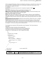
Communication Parameters for AFE2000 Connected to Ethernet
When AFE 2000 is link to Ethernet, please set up the communication parameters base on the table below.
Ethernet master will be able to read/write the frequency word and control word of AFE C2000 after
communication parameters setup
Parameter (Dec)
Function
Set value (Dec)
01-04
Source of operation
command setting
2
04-21
04-22
04-23
IP setting
IP address -1
IP address -2
0
192
168
7-43
Explanation
The operation command is controlled by
communication card.
Static IP(0) / Dynamic distribution IP(1)
IP address 192.168.1.5
IP address 192.168.1.5
Chapter 7 Option CardsAFE2000 Series
Parameter (Dec)
04-24
04-25
04-26
04-27
04-28
04-29
04-30
04-31
04-32
04-33
Function
IP address -3
IP address -4
Netmask -1
Netmask -2
Netmask -3
Netmask -4
Default gateway -1
Default gateway -2
Default gateway -3
Default gateway -4
Set value (Dec)
1
5
255
255
255
0
192
168
1
1
Explanation
IP address 192.168.1.5
IP address 192.168.1.5
Netmask 255.255.255.0
Netmask 255.255.255.0
Netmask 255.255.255.0
Netmask 255.255.255.0
Default gateway 192.168.1.1
Default gateway 192.168.1.1
Default gateway 192.168.1.1
Default gateway 192.168.1.1
Disconnecting CMC- MOD01 from AFE2000 unit
1. Turn off the AFE2000 power. .
2. Remove the two screws (see Figure 6).
3. Twist opens the card clip and inserts the slot type screwdriver to the hollow to prize the PCB off the card clip
(see Figure 7).
4. Twist opens the other card clip to remove the PCB (see Figure 8)
[Figure 7]
[Figure 6]
[Figure 8]
Basice Registers
BR#
R/W
Content
#0
R
#1
R
#2
R
#11
R/W
Modbus Timeout Pre-defined setting: 500 (ms)
#13
R/W
Keep Alive Time Pre-defined setting: 30 (s)
Model name
Explanation
Set up by the system; read only. The model code of
CMC-MOD01=H’0203
Firmware
version
Displaying the current firmware version in hex, e.g. H’0100 indicates the
firmware version V1.00.
Displaying the data in decimal form. 10,000s digit and 1,000s digit are for
Release date of
“month”; 100s digit and 10s digit are for “day”.
the version
For 1 digit: 0 = morning; 1 = afternoon.
7-44
Chapter 7 Option CardsAFE2000 Series
LED Indicator & Troubleshooting
LED
POWER
LINK
Status
Green
Green
Indication
Treatment
On
Power supply in normal status
--
Off
No power supply
Check the power supply
On
Network connection in normal status
--
Network in operation
--
Network not connected
Check if the network cable is
connected
Flashes
Off
Troubleshooting
Abnormality
Cause
Treatment
CMC-MOD01 not connected
to AC motor drive
CMC-MOD01 not connected
to network
Check if AC motor drive is powered, and if the
power supply is normal.
Make sure CMC-MOD01 is connected to AC motor
drive.
Make sure the network cable is correctly connected
to network.
Poor contact to RJ-45
connector
Make sure RJ-45 connector is connected to
Ethernet port.
CMC-MOD01 not connected
to network
Make sure CMC-MOD01 is connected to network.
AC motor drive not powered
POWER LED off
LINK LED off
No module found
Fail to open
CMC-MOD01
setup page
Able to open
CMC-MOD01
setup page but fail
to utilize webpage
monitoring
Fail to send e-mail
PC and CMC-MOD01 in
different networks and
blocked by network firewall.
CMC-MOD01 not connected
to network
Incorrect communication
setting in DCISoft
PC and CMC-MOD01 in
different networks and
blocked by network firewall.
Search by IP or set up relevant settings by AC
motor drive keypad.
Make sure CMC-MOD01 is connected to the
network.
Make sure the communication setting in DCISoft is
set to Ethernet.
Conduct the setup by AFE2000 keypad.
Incorrect network setting in
CMC-MOD01
Check if the network setting for CMC-MOD01 is
correct. For the Intranet setting in your company,
please consult your IT staff. For the Internet setting
in your home, please refer to the network setting
instruction provided by your ISP.
Check if the network setting for CMC-MOD01 is
correct.
Incorrect mail server setting
Please confirm the IP address for SMTP-Server.
Incorrect network setting in
CMC-MOD01
7-45
Chapter 7 Option CardsAFE2000 Series
CMC-PD01
Functions
1.
Supports PZD control data exchange.
2.
Supports PKW polling AFE2000 parameters.
3.
Supports user diagnosis function.
4.
Auto-detects baud rates; supports Max. 12Mbps.
Product Profile
1. NET indicator
2. POWER indicator
3. Positioning hole
4. AFE2000 connection port
5. PROFIBUS DP connection port
6. Screw fixing hole
7. Fool-proof groove
Specifications
PROFIBUS DP Connector
Interface
DB9 connector
Transmission method
High-speed RS-485
Transmission cable
Shielded twisted pair cable
Electrical isolation
500VDC
Communication
Message type
Cyclic data exchange
Module name
CMC-PD01
GSD document
DELA08DB.GSD
Company ID
08DB (HEX)
Serial transmission
speed supported
(auto-detection)
9.6kbps; 19.2kbps; 93.75kbps; 187.5kbps; 125kbps; 250kbps; 500kbps; 1.5Mbps;
3Mbps; 6Mbps; 12Mbps (bits per second)
Electrical Specification
Power supply voltage
5VDC (supplied by AFE2000)
Insulation voltage
500VDC
Power consumption
1W
Weight
28g
7-46
Chapter 7 Option CardsAFE2000 Series
Environment
Noise immunity
ESD(IEC 61800-5-1,IEC 6100-4-2)
EFT(IEC 61800-5-1,IEC 6100-4-4)
Surge Teat(IEC 61800-5-1,IEC 6100-4-5)
Conducted Susceptibility Test(IEC 61800-5-1,IEC 6100-4-6)
Operation /storage
Operation: -10ºC ~ 50ºC (temperature), 90% (humidity)
Storage: -25ºC ~ 70ºC (temperature), 95% (humidity)
Shock / vibration
resistance
International standards: IEC61131-2, IEC68-2-6 (TEST Fc)/IEC61131-2 & IEC
68-2-27 (TEST Ea)
Installation
PROFIBUS DP Connector
PIN
PIN name
Definition
1
-
Not defined
2
-
Not defined
3
Rxd/Txd-P
Sending/receiving data P(B)
4
-
Not defined
5
DGND
Data reference ground
6
VP
Power voltage – positive
7
-
Not defined
8
Rxd/Txd-N
Sending/receiving data N(A)
9
-
Not defined
9
5
6
1
LED Indicator & Troubleshooting
There are 2 LED indicators on CMC-PD01. POWER LED displays the status of the working power. NET LED
displays the connection status of the communication.
POWER LED
LED status
Indication
Treatment
Green light on
Power supply in normal status.
--
Off
No power
Check if the connection between CMC-PD01 and AC
motor drive is normal.
NET LED
LED status
Indication
Treatment
Green light on
Normal status
--
Red light on
CMC-PD01 is not connected to
PROFIBUS DP bus.
Connect CMC-PD01 to PROFIBUS DP bus.
Red light
flashes
Invalid PROFIBUS communication
address
Set the PROFIBUS address of CMC-PD01 between 1 ~
125 (decimal)
Orange light
flashes
CMC-PD01 fails to communication
with AC motor drive.
Switch off the power and check whether CMC-PD01 is
correctly and normally connected to AC motor drive.
7-47
Chapter 7 Option CardsAFE2000 Series
CMC-DN01
Functions
1.
Based on the high-speed communication interface of Delta HSSP protocol, able to conduct immediate
control to AFE2000 unit.
2.
Supports Group 2 only connection and polling I/O data exchange.
3.
For I/O mapping, supports Max. 32 words of input and 32 words of output.
4.
Supports EDS file configuration in DeviceNet configuration software.
5.
Supports all baud rates on DeviceNet bus: 125kbps, 250kbps, 500kbps and extendable serial
transmission speed mode.
6.
Node address and serial transmission speed can be set up on AFE2000 unit.
1.
Power supplied from AFE2000 unit.
Product Profile
1. NS indicator
2. MS indicator
3. POWER indicator
4. Positioning hole
5. DeviceNet connection port
6. Screw fixing hole
7. Fool-proof groove
8. AFE2000 connection port
Specifications
DeviceNet Connector
Interface
5-PIN open removable connector. Of 5.08mm PIN interval
Transmission method
CAN
Transmission cable
Shielded twisted pair cable (with 2 power cables)
Transmission speed
125kbps, 250kbps, 500kbps and extendable serial transmission speed mode
Network protocol
DeviceNet protocol
AFE2000 Connection Port
Interface
50 PIN communication terminal
Transmission method
SPI communication
Terminal function
1. Communicating with AFE2000 unit
2. Transmitting power supply from AFE2000 unit
Communication protocol
Delta HSSP protocol
7-48
Chapter 7 Option CardsAFE2000 Series
Electrical Specification
Power supply voltage
5VDC (supplied by AFE2000)
Insulation voltage
500VDC
Communication wire
power consumption
0.85W
Power consumption
1W
Weight
23g
Environment
Noise immunity
ESD (IEC 61800-5-1,IEC 6100-4-2)
EFT (IEC 61800-5-1,IEC 6100-4-4)
Surge Teat(IEC 61800-5-1,IEC 6100-4-5)
Conducted Susceptibility Test (IEC 61800-5-1,IEC 6100-4-6)
Operation /storage
Operation: -10ºC ~ 50ºC (temperature), 90% (humidity)
Storage: -25ºC ~ 70ºC (temperature), 95% (humidity)
Shock / vibration
resistance
International standards: IEC61131-2, IEC68-2-6 /IEC61131-2 & IEC 68-2-27
DeviceNet Connector
PIN
Signal
Color
Definition
1
V+
Red
DC24V
2
H
White
Signal+
3
S
-
Earth
4
L
Blue
Signal-
5
V-
Black
0V
1
2
3
4
5
LED Indicator & Troubleshooting
There are 3 LED indicators on CMC-DN01. POWER LED displays the status of power supply. MS LED and NS
LED are dual-color LED, displaying the connection status of the communication and error messages.
POWER LED
LED status
Indication
Treatment
On
Power supply in abnormal status.
Check the power supply of CMC-DN01.
Off
Power supply in normal status
--
7-49
Chapter 7 Option CardsAFE2000 Series
NS LED
LED status
Indication
Treatment
Off
No power supply or CMC-DN01 has
not completed MAC ID test yet.
1. Check the power of CMC-DN01 and see if the
connection is normal.
2. Make sure at least one or more nodes are on the
bus.
3. Check if the serial transmission speed of
CMC-DN01 is the same as that of other nodes.
Green light
flashes
CMC-DN01 is on-line but has not
established connection to the master.
1. Configure CMC-DN01 to the scan list of the
master.
2. Re-download the configured data to the master.
Green light on
CMC-DN01 is on-line and is normally
connected to the master
--
Red light
flashes
CMC-DN01 is on-line, but I/O
connection is timed-out.
1. Check if the network connection is normal.
2. Check if the master operates normally.
1.
2.
3.
4.
1. Make sure all the MAC IDs on the network are
not repeated.
2. Check if the network installation is normal.
3. Check if the baud rate of CMC-DN01 is
consistent with that of other nodes.
4. Check if the node address of CMC-DN01 is
illegal.
5. Check if the network power supply is normal.
Red light on
The communication is down.
MAC ID test failure.
No network power supply.
CMC-DN01 is off-line.
MS LED
LED status
Indication
Treatment
Off
No power supply or being off-line
Check the power supply of CMC-DN01 and see of
the connection is normal.
Green light
flashes
Waiting for I/O data
Switch the master PLC to RUN status
Green light on
I/O data are normal
--
Red light
flashes
Mapping error
1. Reconfigure CMC-DN01
2. Re-power AFE2000
Red light on
Hardware error
1. See the error code displayed on AFE2000.
2. Send back to the factory for repair if necessary.
Orange light
flashes
If the flashing lasts for a long time, check if
CMC-DN01 is establishing connection
CMC-DN01 and AFE2000 are correctly installed
with AC motor drive.
and normally connected to each other.
7-50
Chapter 7 Option CardsAFE2000 Series
CMC-EIP01
Functions
1.
Supports Modbus TCP and Ethernet/IP protocol
2.
MDI/MDI-X auto-detect
3.
Baud rate: 10/100Mbps auto-detect
4.
AFE2000 keypad/Ethernet configuration
5.
Virtual serial port
Product Profile
[Figure1]
1. Screw fixing hole
2. Positioning hole
3. AFE2000 connection port
4. LINK indicator
5. RJ-45 connection port
6. POWER indicator
7. Fool-proof groove
Specifications
Network Interface
Interface
RJ-45 with Auto MDI/MDIX
Number of ports
1 Port
Transmission method
IEEE 802.3, IEEE 802.3u
Transmission cable
Category 5e shielding 100M
Transmission speed
10/100 Mbps Auto-Detect
Network protocol
ICMP, IP, TCP, UDP, DHCP, HTTP, SMTP, MODBUS OVER TCP/IP, EtherNet/IP, Delta
Configuration
Electrical Specification
Weight
25g
Insulation voltage
500VDC
Power consumption
0.8W
Power supply voltage
5VDC
7-51
Chapter 7 Option CardsAFE2000 Series
Environment
Noise immunity
ESD (IEC 61800-5-1,IEC 61000-4-2)
EFT (IEC 61800-5-1,IEC 61000-4-4)
Surge Test (IEC 61800-5-1,IEC 61000-4-5)
Conducted Susceptibility Test (IEC 61800-5-1,IEC 61000-4-6)
Operation/storage
Operation: -10°C ~ 50°C (temperature), 90% (humidity)
Storage: -25°C ~ 70°C (temperature), 95% (humidity)
Vibration/shock
immunity
International standard: IEC 61800-5-1, IEC 60068-2-6/IEC 61800-5-1, IEC 60068-2-27
Installation
Connecting CMC-EIP01 to Network
1. Turn off the AFE2000 power.
2. Open up AFE2000 cover.
3. Connect CAT-5e network cable to RJ-45 port on CMC-EIP01
(See Figure 2).
[Figure 2]
RJ-45 PIN Definition
PIN
Signal
Definition
PIN
Signal
Definition
1
Tx+
Positive pole for
data transmission
5
--
N/C
2
Tx-
Negative pole for
data transmission
6
Rx-
Negative pole for
data receiving
3
Rx+
Positive pole for
data receiving
7
--
N/C
4
--
N/C
8
--
N/C
Connecting CMC-EIP01 to AFE2000
1.
Turn off the AFE2000 power.
2.
Open up AFE2000 cover.
3.
Place the insulation spacer into the positioning pin at Slot 1 (shown in Figure 3), and aim the two holes on
the PCB at the positioning pin. Press the pin to clip the holes with the PCB (see Figure 4).
4.
Screw up at torque 6 ~ 8 kg-cm (5.21 ~ 6.94 in-lbs) after the PCB is clipped with the holes (see Figure 5).
7-52
Chapter 7 Option CardsAFE2000 Series
Slot 3
Slot 2 Slot 1
[Figure 3]
[Figure 4]
[Figure 5]
Communication Parameters for AFE2000 Connected to Ethernet
When AFE2000 is connected to Ethernet network, please set up the communication parameters for it
according to the table below. The Ethernet master is only able to read/write the frequency word and control
word of AFE2000 after the communication parameters are set.
Parameter (Dec)
Function
Set value (Dec)
Explanation
01-04
Setting up source of
operation command
5
The operation command is controlled by
communication card.
04-21
IP setting
0
Static IP(0) / Dynamic distribution IP(1)
04-22
IP address -1
192
IP address 192.168.1.5
04-23
IP address -2
168
IP address 192.168.1.5
04-24
IP address -3
1
IP address 192.168.1.5
04-25
IP address -4
5
IP address 192.168.1.5
04-26
Netmask -1
255
Newmask 255.255.255.0
04-27
Netmask -2
255
Newmask 255.255.255.0
04-28
Netmask -3
255
Newmask 255.255.255.0
04-29
Netmask -4
0
Newmask 255.255.255.0
04-30
Default gateway -1
192
Default gateway 192.168.1.1
04-31
Default gateway -2
168
Default gateway192.168.1.1
04-32
Default gateway -3
1
Default gateway192.168.1.1
04-33
Default gateway -4
1
Default gateway192.168.1.1
7-53
Chapter 7 Option CardsAFE2000 Series
Disconnecting CMC- EIP01 from AFEC2000
1. Turn off the AFEC2000 power.
2. Remove the two screws (see Figure 6).
3. Twist opens the card clip and inserts the slot type screwdriver to the hollow to prize the PCB off the card clip
(see Figure 7).
4. Twist opens the other card clip to remove the PCB (see Figure 8).
[Figure 6]
[Figure 7]
[Figure 8]
LED Indicator & Troubleshooting
There are 2 LED indicators on CMC-EIP01. The POWER LED displays the status of power supply, and the
LINK LED displays the connection status of the communication.
LED Indicators
LED
POWER
LINK
Status
Green
Green
Indication
Treatment
On
Power supply in normal status
--
Off
No power supply
Check the power supply.
On
Network connection in normal
status
--
Network in operation
--
Network not connected
Check if the network cable is
connected.
Flashes
Off
Troubleshooting
Abnormality
POWER LED off
Cause
Treatment
AFE2000 is not powered
Check if AFE2000 is connected to power supply,
and if the power supply is normal.
CMC-EIP01 not connected to
AC motor drive
Make sure CMC-EIP01 is connected to AFE2000.
7-54
Chapter 7 Option CardsAFE2000 Series
Abnormality
LINK LED off
No communication
card found
Fail to open
CMC-EIP01 setup
page
Able to open
CMC-EIP01 setup
page but fail to
utilize webpage
monitoring
Cause
Treatment
CMC-EIP01 not connected to
network
Make sure the network cable is correctly connected
to network.
Poor contact to RJ-45
connector
Make sure RJ-45 connector is connected to
Ethernet port.
CMC-EIP01 not connected to
network
Make sure CMC-EIP01 is connected to network.
PC and CMC-EIP01 in
different networks and blocked
by network firewall.
Search by IP or set up relevant settings by AC
motor drive keypad.
CMC-EIP01 not connected to
network
Incorrect communication
setting in DCISoft
Make sure CMC-EIP01 is connected to the
network.
Make sure the communication setting in DCISoft is
set to Ethernet.
PC and CMC-EIP01 in
different networks and blocked
by network firewall.
Conduct the setup by the AFE2000 keypad.
Incorrect network setting in
CMC-EIP01
Check if the network setting for CMC-EIP01 is
correct. For the Intranet setting in your company,
please consult your IT staff. For the Internet setting
in your home, please refer to the network setting
instruction provided by your ISP.
Check if the network setting for CMC-EIP01 is
correct.
Incorrect mail server setting
Please confirm the IP address for SMTP-Server.
Incorrect network setting in
CMC-EIP01
Fail to send e-mail
7-55
Chapter 7 Option CardsAFE2000 Series
EMC-COP01
RJ-45Pin definition
Pin
1
2
3
7
Definition
CAN_H bus line (dominant high)
CAN_L bus line (dominant low)
Ground/0V/VGround/0V/V-
Female
Ma le
Pin name
CAN_H
CAN_L
CAN_GND
CAN_GND
Specification
Interface
RJ-45
Number of ports
1 Port
Transmission method
CAN
Transmission cable
CAN standard cable
Transmission speed
1M 500k 250k 125k 100k 50k
Communication protocol
CANopen
CANopen Communication Cable
Model: TAP-CB03, TAP-CB04
Title
Part No.
1
2
TAP-CB03
TAP-CB04
L
mm
500 10
1000 10
inch
19 0.4
39 0.4
CANopen Dimension
Model: TAP-CN03
NOTE
Please refer to CANopen user manual for more details on CANopen operation. CANopen user manual is also
available on Delta website: http://www.delta.com.tw/industrialautomation/.
7-56
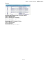
Chapter 8 SpecificationsAFE2000 Series
Chapter 8 Specifications
230V series
460V series
Frame Size
B
C
D
Model AFE-_ _ _A_ _A
Applicable power(kW)
Rate input voltage(V)
Rated input current(A)
Voltage control
Overload capacity
Frequency tolerance
Power factor at input
side
Harmonic (%)
Protection level
Cooling method
075
7.5
150
220
15
22
170~ 250Vac
70
95
300~370Vdc
370
37
075
7.5
150
15
150
20
35
35
B
C
220
370
22
37
325~ 500Vac
50
75
600~740Vdc
D
450
45
750
75
95
160
150% 60sec
5%
0.95 to above 0.99
Smaller than 5% (under rated current)
IP20/NEMA 1
Fan cooling
For indoor altitude 0~1000m(3280.60 feet) , keep it out of direct sunlight, corrosive
gasses, liquid and dust.
Installation environment
For altitude above 1000m(3280.60 feet), please decreases 3% of rated current for
every 500m (1640.40 feet) increases. The maximum altitude is 2500m (8202.00 feet)
Ambient temperature
-10~50℃
Storage/transportation
-25~+65℃
temperature
Ambient humidity
Lower than 90%RH (non-condensing)
Vibration
5.9m/ s²(0.6G) less than 10~55Hz (JIS C0040)
Certifications
GB/T12668-2
8-57
(certification in progress)
This page is intentionally left blank
8-58
Chapter 9 Digital KeypadAFE2000 Series
Chapter 9 Digital Keypad
KPC-CC01(Optional)
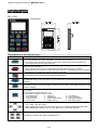
KPC-CE01
A : LED Disp lay
D ispla y freq uen cy, cu rre nt, vo ltag e and erro r etc.
B : Status Indi cator
F: Fre que ncy C omma nd
H: Outp ut Frequ ency
U: User De fine d Uni ts
ERR: CAN Erro r Ind icator
RU N: CAN Ru n Indi ca tor
C : Func tion
(Re fer to the chart foll ow s for deta il de scripti on )
Communication interface:RJ-45 (socket), RS-485 interface
Installation Method:
Embedded mounting. Flat installation to the control box surface and the front facet is water proof.
Other optional accessories model: MKC-KPPK with protection level IP56 can be installed by flang mounting or
embedded mounting.
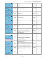
Descriptions of Keypad Functions
Key
Descriptions
Starts Operation
1.
It is only valid when the source of operation command is from the keypad.
2.
It can operate the AFE2000 by the function setting and the RUN LED will be ON.
3.
It can be pressed again and again at stop process.
Stop Command Key. This key has the highest processing priority in any situation.
1.
When it receives STOP command, no matter the AC motor drive is in operation or stop
status, the AC motor drive needs to execute “STOP” command.
2.
The RESET key can be used to reset the drive after the fault occurs. For those faults that
can’t be reset by the RESET key, see the fault records after pressing MENU key for
details.
(This function is not supported.)
ENTER Key
Press ENTER and go to the next level. If it is the last level then press ENTER to execute the command.
ESC Key
ESC key function is to leave current menu and return to the last menu. It is also functioned as
a return key in the sub-menu.
Press MENU to return to the main menu page.
MENU content:
(KPC-CE01 does not support function 4~12; KPC-CC01 does not support function 4,5,7.)
1.
2.
3.
Detail Parameter
Copy Parameter
Keypad Locked
5.
6.
7.
Copy PLC
Fault Record
Quick/Simple Setup
9-59
9.
10.
11.
Time Setup
Language Setup
Startup Menu
Chapter 9 Digital KeypadAFE2000 Series
Display Setup
Main Page
4.
PLC Function
1.
2.
Direction: Left/Right/Up/Down
In the numeric value setting mode, it is used to move the cursor and change the numeric
value.
In the menu/text selection mode, it is used for item selection.
3.
8.
12.
Function (This function is not supported)
(This function is not supported)
(This function is not supported)
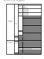
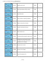
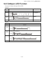
Descriptions of LED Functions
LED
Descriptions
Steady ON: operation indicator of AFE2000.
Steady OFF: AFE2000 does not perform the operation command
Steady ON: stop indicator of the AC motor drive. The light ON represents the AFE2000 is in
stop status.
Steady OFF: AFE2000 does not perform “STOP” command.
(This function is not supported)
(This function is not supported)
(This function is not supported)
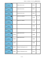
RUN LED:
LED
status
OFF
CANopen at initial
Condition/State
No LED
Blinking CANopen at pre-operation
ON
200
Blinking ms
OFF
CANopen ~”RUN”
Single
flash
ON
200
ms
CANopen at stopped
ON
200
Single flash ms
OFF
200
ms
1000
ms
CANopen at operation status
No LED
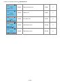
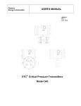
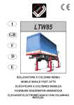
ERR LED:
CANopen ~”ERR” LED
status
OFF
Condition/ State
No Error
9-60
Chapter 9 Digital KeypadAFE2000 Series
Single At lease one message fail
flash
ON
200
Single flash ms
OFF
Double Guarding fail or heartbeat fail
flash
ON
200 200
Double flash ms
ms
OFF
Triple SYNC fail
flash
ON
200
Triple flash ms
OFF
200
ms
200
ms
ON
1000
ms
1000
ms
200
ms
200
ms
200
ms
1000
ms
Bus off
Optional Accessory for Digital Keypad: RJ45 Extension Lead
Part No.
Description
CBC-K3FT
RJ45 Communication Cable 3 feet
CBC-K5FT
RJ45 Communication Cable 5 feet
CBC-K7FT
RJ45 Communication Cable 7 feet
CBC-K10FT
RJ45 Communication Cable 10 feet
CBC-K16FT
RJ45 Communication Cable 16 feet
9-61
Chapter 9 Digital KeypadAFE2000 Series
This page is intentionally left blank
9-62
Chapter 10 Summary of Parameter SettingsAFE2000 Series
Chapter 10 Summary of Parameter Settings
This chapter provides summary of parameter settings for user to gather the parameter setting ranges,
factory settings and set parameters. The parameters can be set, changed and reset by the digital keypad.
NOTE
1) : the parameter can be set during operation
2) For more detail on parameters, please refer to Ch11 Description of Parameter Settings.
00 Display Parameters
Parameter
00-00
00-01
00-02
00-03
00-04
00-05
00-06
00-07
00-08
00-09
00-10
00-11
00-12
Settings
Explanation
Identity Code of AFE2000
Display AFE2000 Rated
Current
Software version
Current of AFE Unit
Mains Input Frequency
DC-BUS voltage
Display the Input Power of
AFE2000 (kW )
Display the Amount of Power
Consumed kWh (High Word)
Display the Amount of Power
Consumed kWh (Low Word)
Display the Amount of Power
Regenerated kWh (High
Word)
Display the Amount of Power
Regenerated kWh (Low
Word)
Display Total Power kWh
(High Word)
* Total Power = Power
Consumed + Power
Regenerated
Display Total Power AAA
kWh (Low Word)
*Total Power = Power
Consumed+ Power
Factory
Setting
0: 230V, 7.5kW
1: 460V, 7.5Kw
2: 230V, 15kW
3: 460V, 15kW
4: 230V, 22kW
5: 460V, 22kW
6: 230V, 37kW
7: 460V, 37kW
9: 460V, 45kW
11: 460V, 75kW
0: 35A
1: 20A
2: 70A
3: 35A
4: 95A
5: 50A
6: 150A
7: 75A
9: 95A
11: 160A
Read only
Read only
Read only
Read only
-300.0 ~300.0
Read only
Read only
Read only
Read only
Read only
0~9999
Read only
0 ~ 9999
Read only
0 ~ 9999
Read only
0 ~ 9999
Read only
-9999 ~ 9999
Read only
-9999 ~ 9999
Read only
10-63
Read only
Read only
Chapter 10 Summary of Parameter SettingsAFE2000 Series
Parameter
Factory
Settings
Explanation
Setting
00-19
00-20
Regenerated
Display AFE2000 Internal
Temperature (℃)
IGBT Temperature (℃)
Digital Input Status
(ON/OFF )
Digital Output Status
(ON/OFF)
DC Bus Voltage at Fault
Mains Input Frequency at
Fault
Current value at Fault
1st Recent Fault Record
00-21
00-22
2nd Recent Fault Record
3rd Recent Fault Record
0: No Fault Record
3 : ocn
O
O
00-23
4th Recent Fault Record
4: GFF
O
O
Read only
th
5 : occ (only for frame D)
O
O
Read only
th
6: ocs
O
O
Read only
9: oVn
10: oVs
13 : LVn
14: LVs
15: PHL (Input phase loss)
16: oH1 (IGBT over-heat)
17: oH2 (Capacitance over-heat)
18: ot1 (circuit error)
19: ot2 (circuit error)
20: oL (150% 1Min, AFE2000
over-load)
30: cF1 (Memory write-in error)
31: cF2 (Memory read error)
32: cd0 Isum current detection
error
33: cd1 U-phase current detection
error
34: cd2 V-phase current detection
error
35: cd3 W-phase current
detection error
36: Hd0 cc current detection error
37: Hd1 oc current detection error
38: Hd2 ov current detection error
47: S1 Enable Error
48: BST Voltage boosting error
49: EF1
52: PcodE Code error
54: cE1 communication error
(warn)
55: cE2 communication error
(warn)
56: cE3 communication error
(warn)
57: cE4 communication error
(warn)
O
O
O
O
O
O
O
O
O
O
O
O
O
O
O
O
O
O
O
O
O
O
O
O
O
O
O
00-13
00-14
00-15
00-16
00-17
00-18
00-24
00-25
5 Recent Fault Record
6 Recent Fault Record
Read only
Read only
Read only
Read only
Read only
Read only
Read only
Read only
Read only
Read only
Read only
Read only
Read only
Fault
Retry
10-64
Fault
Reset
Read only
Read only
Read only
Read only
Chapter 10 Summary of Parameter SettingsAFE2000 Series
Parameter
Factory
Settings
Explanation
Setting
00-26
Electricity cost (Low Word)
58: cE10 communication Time
Out(warn)
59: cP10 PU Board Time
out(warn)
65: PCE phase connection error
66: PLE Phase lock error
67: LDC control voltage is too low
68: RIP DC Bus ripple is too large
Read only
00-27
Electricity cost (High Word)
Read only
Read only
00-28
Input AC voltage
0~6553.5
Read only
10-65
O
O
O
O
O
O
O
O
O
O
O
Read only
Chapter 10 Summary of Parameter SettingsAFE2000 Series
01 Basic Parameter
Parameter
Explanation
01-00
Parameter Reset
01-01
Start-up Screen Display
01-02
Password Input
01-03
Password Set
01-04
01-05
Source of the Operation
Command
Control Mode Selection
01-06
01-07
01-08
Accel. Time
Decel. Time
DC BUS Voltage Command
01-09
01-10
01-11
DC BUS Gain Ratio of P
DC BUS Gain Ratio of I
DC BUS Bandwidth Control
01-12
Inductance Value of Reactor
Settings
0: No function
1: Read only, write is disable
8: Keypad lock
10: All parameters are reset to the factory settings
0: Mains input frequency
1: DC BUS voltage
2: Output current
1~9998, 10000~65535
0~2: times of wrong password input
1~9998, 10000~65535
0: No password set or successful input in Pr.01-02
1: Password has been set, parameter is locked
1: External terminal
2: RS-485 serial communication or digital keypad
(KPVL-CC01)
0: AFE mode
1: Regenerate mode
0.00~600.00 sec
0.00~600.00sec
220V : 300~370V
440V : 600~740V
0~100%
0~100%
0~75
230V, 7.5kW
460V, 7.5kW
460V, 15kW
230V, 15kW
230V, 22kW
460V, 22kW
230V, 37kW
460V, 37kW
460V, 45kW
460V, 75kW
0(230V, 7.5kW):
1(460V, 7.5Kw):
2(230V, 15kW):
3(460V, 15kW):
4(230V, 22kW):
5(460V, 22kW):
6(230V, 37kW):
7(460V, 37kW):
9(460V, 45kW):
11(460V, 75kW):
10-66
2.10
7.32
1.32
5.28
0.88
3.52
0.50
1.96
1.76
1.02
Factory
Setting
0
0
0
0
2
0
2
2
340
680
100
100
18
18
18
22
22
22
22
22
22
22
0.88
Chapter 10 Summary of Parameter SettingsAFE2000 Series
02 Digital Input/Output Parameters
Parameter
Explanation
02-00
Multi-Function Input Command
1 (MI1)
Multi-Function Input Command
2 (MI2)
Multi-Function Input Command
3 (MI3)
Multi-Function Input Command
4 (MI4)
Multi-Function Input Command
5 (MI5)
Multi-Function Input Command
6 (MI6)
Multi-Function Input Command
7 (MI7)
Multi-Function Input Command
8 (MI8)
Digital Input Response Time
Digital Input Operation
Direction
Multi-Function Output 1 RA1,
RB1, RC1(Relay1)
Multi-Function Output 2 RA2,
RB2, RC2(Relay2)
Multi-Function Output 3 (MO1)
Multi-Function Output 4 (MO2)
02-01
02-02
02-03
02-04
02-05
02-06
02-07
02-08
02-09
02-10
02-11
02-12
02-13
02-14
Multi-Function Output
Direction
Settings
0: Disable
1: RUN
2: STOP
3: EF1
4: RESET
5 : MASTER/SLAVE (will be available soon)
6 : ENABLE
7: EF2
8: EF3
9: oH3
Factory
Setting
1
2
3
4
0
0
0
0.001~ 30.000 sec
0~65535
0:
1:
2:
3:
4:
5:
6:
7:
8:
Disable
Operation indication
DCBUS command attained
AFE Ready (Phase lock complete)
Fault Indication
Overheat warning (03-05&03-06)
Output warning
Drive / Regenerate
Fault Reset
0.005
0
2
3
0
0
0
0~65535
10-67
Chapter 10 Summary of Parameter SettingsAFE2000 Series
03 Special Protection Parameters
Parameter
Explanation
03-00
Low Voltage Level
03-01
03-02
03-03
Current Limit (Drive)
Current Limit (Regeneration )
Phase Lock Frequency
Deviation Level
Phase Lock Frequency
Deviation Time
IGBT Temperature Warning
Level
Ambient Temperature
Warning Level
Numbers of Fault Retry
Fault Retry Reset Time
Fan Control
(only ON/OFF for Frame B)
03-04
03-05
03-06
03-07
03-08
03-09
03-10
03-12
Voltage Boosting Error (Level
Setting)
Voltage Boosting Error (Time
Setting)
Work Delete
03-13
Electricity cost
03-11
Settings
Factory
Setting
230V model: 160.0~220.0Vdc
460V model: 320.0~440.0Vdc
0~250%
0~250%
0.00~10.00Hz
180
360
150
150
4.00
0~1000ms
150
0.0~110.0 ℃
100.0
0.0~110.0 ℃
60.0
0~10
1~600 sec
0: Fan is always ON
1: As the drive stops, the fan will continue to run for
60 sec then stop.
2: Fan stops when the drive stops operation
3: Fan ON/OFF depends on the ambient
temperature
4: Fan is always OFF
0.0V ~15.0V
0
600
2
200ms~1000ms
200
1: Delete (when deleting is completed, Pr.03-12
reset to 1)
0~6553.5
10-68
5.0
0
3.0
Chapter 10 Summary of Parameter SettingsAFE2000 Series
04 通訊參數
Parameter
Explanation
04-00
04-01
Communication Address
Transmission Speed
(Keypad)
Transmission Fault Treatment
(Keypad)
04-02
04-03
04-04
Time-out Detection (Keypad)
Communication Protocol
(Keypad)
04-05
04-06
Response Delay Time
COM2Transmission Speed
(Keypad)
COM2 Transmission Fault
Treatment (Keypad)
04-07
04-08
04-09
04-10
COM2 Time-out Detection
(Keypad)
COM2 Communication
Protocol (Keypad)
Communication Card Type
Settings
1~254
4.8~115.2Kbps
0: Warn and continue operation
1: Warn and ramp to stop
2: Reserved
3: No treatment and no warn
0.0~100.0 sec
0: 7N1 (ASCII)
1: 7N2 (ASCII)
2: 7E1 (ASCII)
3: 7O1 (ASCII)
4: 7E2 (ASCII)
5: 7O2 (ASCII)
6: 8N1 (ASCII)
7: 8N2 (ASCII)
8: 8E1 (ASCII)
9: 8O1 (ASCII)
10: 8E2 (ASCII)
11: 8O2 (ASCII)
12: 8N1 (RTU)
13: 8N2 (RTU)
14: 8E1 (RTU)
15: 8O1 (RTU)
16: 8E2 (RTU)
17: 8O2 (RTU)
0.0~200.0ms
4.8~115.2Kbps
0: Warning and continue to operate
1: Warn and ramp to stop
2: Warn and coast to stop
3: No warning and continue to operate
0.0~100.0 sec
0:
1:
2:
3:
4:
5:
6:
7:
8:
9:
10:
11:
12:
13:
14:
15:
16:
17:
0:
1:
7N1 (ASCII)
7N2 (ASCII)
7E1 (ASCII)
7O1 (ASCII)
7E2 (ASCII)
7O2 (ASCII)
8N1 (ASCII)
8N2 (ASCII)
8E1 (ASCII)
8O1 (ASCII)
8E2 (ASCII)
8O2 (ASCII)
8N1 (RTU)
8N2 (RTU)
8E1 (RTU)
8O1 (RTU)
8E2 (RTU)
8O2 (RTU)
No communication card
DeviceNet Slave
10-69
Factory
Setting
1
19.2
3
0
13
2
19.2
3
0.0
13
0
Chapter 10 Summary of Parameter SettingsAFE2000 Series
Parameter
04-11
Explanation
CANopen Baud Rate
04-12
CANopen Slave Address
04-13
CANopen Communication
Status
04-14
04-15
CANopen Warning Record
04-16
04-17
04-18
Communication Card
Firmware Version
Product Code
Fault Code
Communication Card Address
04-19
Setting of DeviceNet Speed
04-20
04-21
04-22
04-23
Additional Setting of
DeviceNet Speed
Communication Card IP
Configuration
Communication Card IP
Address 1
Communication Card IP
Settings
2: Profibus-DP Slave
3: CANopen Slave/Master
4: Modbus-TCP Slave
5: EtherNet/IP Slave
6~8: Reserved
0: 1M
1: 500k
2: 250k
3: 125k
4: 100k (Delta only)
5: 50k
0: Disable
1~127
0: Node Reset State
1: Com Reset State
2: Boot up State
3: Pre Operation State
4: Operation State
5: Stop State
bit 0: CANopen Guarding Time out
bit 1: CANopen Heartbeat Time out
bit 2: CANopen SYNC Time out
bit 3: CANopen SDO Time out
bit 4: CANopen SDO buffer overflow
bit 5: Can Bus Off
bit 6: Error protocol of CANopen
Factory
Setting
0
0
0
0
Read only
##
Read only
Read only
DeviceNet: 0-63
Profibus-DP: 1-125
Standard DeviceNet:
0: 100Kbps
1: 125Kbps
2: 250Kbps
3: 1Mbps (Delta only)
##
##
Non standard DeviceNet:
(Delta only)
0: 10Kbps
1: 20Kbps
2: 50Kbps
3: 100Kbps
4: 125Kbps
5: 250Kbps
6: 500Kbps
7: 800Kbps
8: 1Mbps
0: Disable
In this mode, baud rate can only be 0,1,2,3 as a
standard DeviceNet setting.
1: Enable
In this mode, the baud rate of DeviceNet can be
same as CANopen (0-8).
0: Static IP
1: Dynamic IP (DHCP)
1
2
0
0
0~255
0
0~255
0
10-70
Chapter 10 Summary of Parameter SettingsAFE2000 Series
Parameter
04-24
04-25
04-26
04-27
04-28
04-29
04-30
04-31
04-32
04-33
04-34
04-35
04-36
Explanation
Address 2
Communication Card IP
Address 3
Communication Card IP
Address 4
Communication Card
Address Mask 1
Communication Card
Address Mask 2
Communication Card
Address Mask 3
Communication Card
Address Mask 4
Getway Address 1 of the
Communication Card
Getway Address 2 of the
Communication Card
Getway Address 3 of the
Communication Card
Getway Address 4 of the
Communication Card
Password for Communication
Card (Low word)
Password for Communication
Card (High word)
Communication Card Reset
04-37
Communication Card
Additional Setting
04-38
Communication Card Status
Settings
Factory
Setting
0~255
0
0~255
0
0~255
0
0~255
0
0~255
0
0~255
0
0~255
0
0~255
0
0~255
0
0~255
0
0~255
0
0~255
0
0: No function
1: Reset (Returns to factory setting.)
Bit0: Enable IP filter
Bit 1: Enable to write internet parameters (1bit).
This bit will change to disable when it finishes
saving the internet parameter updates.
Bit 2: Enable login password (1bit). This bit will
change to disable when it finishes saving the
internet parameter updates.
Bit 0: password enable
When the communication card is set with
password, this bit is enabled. When the password
is cleared, this bit is disabled.
10-71
0
0
0
Chapter 10 Summary of Parameter SettingsAFE2000 Series
This page is intentionally left blank
10-72
Chapter 11 Description of Parameter SettingsAFE2000 Series
Chapter 11 Description of Parameter Settings
00 Display Parameters
This parameter can be set during the operation.
Identity Code of AFE2000
Factory Setting: Read only
Settings Display is different for different models. Read only.
Display AFE2000 Rated Current
Factory Setting: Read only
Settings Display is different for different models. Read only.
Pr. 00-00 displays the identity code of the AC motor drive. Using the following table to check if
Pr.00-01 setting is the rated current of the AC motor drive. Pr.00-01 corresponds to the identity
code Pr.00-01.
The factory setting is the rated current for normal duty.
Pr.00-00 disaplays the identity code of AFE2000 and the code is set by the factory. Pr.00-01 is the
rated current corresponds to its AFE2000 model (Pr.00-01). The corresponding current is shown at
following:
Input voltage
Pr.00-00
Applicable power
range of AC motor
drive (kW)
Rated input current
0
75
AFE2000 Corresponding Chart
230V
2
4
6
1
3
15
22
35
7.5
15
5
22
7
37
9
45
11
75
35
70
50
75
95
160
95
150
20
35
460V
Software version
Factory Setting: #.##
Settings Read only (The display content is different by factory version.)
Current of AFE Unit
Factory Setting: #.##
Settings Read only (The display content is different by factory version.)
Mains Input Frequency (Line frequency)
Factory Setting: #.##
Settings Read only (The display content is different by factory version.)
DC-BUS voltage
Factory Setting: #.##
Settings Read only (The display content is different by factory version.)
Display the Input Power of AFE2000 (kW )
Factory Setting: #.##
Settings -300.0~300.0
Display the Amount of Power Consumed kWh (High Word)
Factory Setting: #.##
Settings 0~9999
Display the Amount of Power Consumed kWh (Low Word)
Factory Setting: #.##
Settings 0~9999
Display the Amount of Power Regenerated kWh (High Word)
Factory Setting: #.##
Settings 0~9999
11-73
Chapter 11 Description of Parameter SettingsAFE2000 Series
Display the Amount of Power Regenerated kWh (Low Word)
Factory Setting: #.##
Settings 0~9999
Display Total Power kWh (High Word)
* Total Power = Power Consumed + Power Regenerated)
Factory Setting: #.##
Settings -9999~9999
Display Total Power AAA kWh (Low Word)
*Total Power = Power Consumed+ Power Regenerated
Factory Setting: #.##
Settings -9999~9999
When low word >10000 or low word < 10000, the high word adds 1 and the low word would return
to 0. The maximum dislapy value for high word is 9999 and -9999, when high word > 9999, the
display value will be 9999 and when high word < -9999, the display value will be -9999.
Display AFE2000 Internal Temperature (℃)
Factory Setting: #.##
Settings Read only
IGBT Temperature (℃)
Factory Setting: #.##
Settings Read only
Digital Input Status (ON/OFF )
Factory Setting: #.##
Settings Read only
Digital Output Status (ON/OFF)
Factory Setting: #.##
Settings Read only
DC Bus Voltage at Fault
Factory Setting: #.##
Settings Read only
Mains Input Frequency at Fault
Factory Setting: #.##
Settings Read only
Current value at Fault
Factory Setting: #.##
Settings Read only
1st Recent Fault Record
2nd Recent Fault Record
3rd Recent Fault Record
4th Recent Fault Record
5th Recent Fault Record
6th Recent Fault Record
Fault
Code
Settings
0: No Fault Record
3 : ocn
4: GFF
Factory Setting: 0
Fault
Fault
Retry Reset
O
O
O
11-74
O
Chapter 11 Description of Parameter SettingsAFE2000 Series
5 : occ (only for frame D)
6: ocs
9: oVn
10: oVs
13 : LVn
14: LVs
15: PHL (Input phase loss)
16: oH1 (IGBT over-heat)
17: oH2 (Capacitance over-heat)
18: ot1 (circuit error)
19: ot2 (circuit error)
20: oL (150% 1Min, AFE2000 over-load)
30: cF1 (Memory write-in error)
31: cF2 (Memory read error)
32: cd0 Isum current detection error
33: cd1 U-phase current detection error
34: cd2 V-phase current detection error
35: cd3 W-phase current detection error
36: Hd0 cc current detection error
37: Hd1 oc current detection error
38: Hd2 ov current detection error
47: S1 Enable Error
48: BST Voltage boosting error
49: EF1
52: PcodE Code error
54: cE1 communication error (warn)
55: cE2 communication error (warn)
56: cE3 communication error (warn)
57: cE4 communication error (warn)
58: cE10 communication Time Out(warn)
59: cP10 PU Board Time out(warn)
65: PCE phase connection error
66: PLE Phase lock error
67: LDC control voltage is too low
68: RIP DC Bus ripple is too large
O
O
O
O
O
O
O
O
O
O
O
O
O
O
O
O
O
O
O
O
O
O
O
O
O
O
O
O
O
O
O
O
O
O
O
O
O
O
Electricity cost (Low Word)
Factory Setting: #.##
Settings Read only
Electricity cost (High Word)
Factory Setting: #.##
Settings Read only
Input AC voltage
Factory Setting: #.##
Settings 0~6553.5
11-75
Chapter 11 Description of Parameter SettingsAFE2000 Series
01 Basic Parameters
This parameter can be set during the operation.
Parameter Reset
Factory Setting: 0
Settings 0: No function
1: Read only, write is disable
8: Keypad lock
10: All parameters are reset to the factory settings
When it is set to 1, all parameters are read only except Pr.01-00 ~Pr.01-03. Password setting
function can still be used to to prevent parameter setting changes when false operation.
When it is set to 10, all parameters are reset to factory settings. If parameters are locked, please
clear the password to return the parameters setting back to factory setting.
When it is set to 8, digital keypad is disabled. All parameters are disabled except Pr. 01-00 and
Pr.01-02.
Start-up Screen Display
Factory Setting: 0
Settings 0: Mains input frequency
1: DC BUS voltage
2: Output current
Password Input
Factory Setting: 0
1~9998,10000~65535
Settings
Display 0~2: times of wrong password input
Pr.01-02 is used to unlock the parameter only if Pr.01-03 password is set. Enter the same
password as setted in Pr.01-03. The purpose of this parameter is to prevent the parameter
changes caused by misoperation.
When the user have forgotten the password, clear the setting by input 9999 and press ENTER key,
then input 9999 again and press Enter within 10 seconds. After parameters are unlocked, all
settings will return to factory setting.
Password Set
Factory Setting: 0
Settings 1~9998,10000~65535
Display 0: No password set or successful input in Pr.01-02
1: Password has been set, parameter is locked
This parameter is used for password protection. Setting the password for first time, enter the
password and if value display as 1, it means password setting is success. If display value is 0, it
means no password has been set and password protection function is not yet activated, all
parameters can be changed (Pr.01-03 setting can also be changed, please re-set your password).
When the display value is 1, all parameters can be changed. In order to unlock the parameters,
please go to Pr.01-02 and enter the right password, the display value will then be changed to 0
and all parameters can be changed. Note: If the display value is 0, it means the password is
cleared, there will be no password protection when re-activating the AFE2000 unit. If display value
is 1, it means the password is set (parameter locked) for everytime the AFE2000 unit is
re-activated; in this case, enter the password to Pr.01-02 to unlock the parameters for change
setting.
How to make the password valid again after clearing the password:
Method 1: Enter a new password to Pr.01-03.
Method 2: Re-activate the unit and password protection setting will return to previous setting.
Method 3: Enter a non-password digits to Pr.01-02.
11-76
Chapter 11 Description of Parameter SettingsAFE2000 Series
Password Set
Pass word Input
01-03
01-03
Pr.01-03 displays
01 when the correct
password is entered
into Pr.01-03.
Pass word Forgotten
01-03
When the correc t password i s en tered
into Pr.01-02 ,Pr.0 1-03 d ispl ays 00.
Enter 9 999 and press ENT ER,
repea t this st ep twice. The
parameter setting s will rese t to
factory setting .
Pr.01-02
Incorre ct Password
Correct Pa ssword
Pr.01-02
Pr.01-03
When co rrect pa ssword
ente re d in to Pr.01-0 2,
Pr.01-03 displays 0 0.
It a llows three wrong pas sword in puts:
1s t time displays " 01" if password is i ncorrect.
2nd tim e displays " 02", if pa ssword is i ncorrect.
3rd time disp lays "Pcode"(bl inkin g)
The keypad wi ll be locked , when wron g
password i s e ntered for three time s. Ple ase
resta rt the drive and enter the pa ssword agai n.
Source of Operation Command
Factory Setting: 0
Settings 1: External terminal
2: RS-485 serial communication or digital keypad (KPVL-CC01)
For the factory released AFE2000 unit, the digital keypad is not set as the source of operation
command, user can perform operation control via the external terminal or the communication
interface (RS485).
When the PU led on the interface is lightened, the digital keypad can now perform the operation
command. (For optional accessories selection, please refer to Ch 06 Optional Acessories- Digital
keypad section.)
Control Mode Selection
Factory Setting: 0
Settings 0:AFE2000 mode
1:Regenerate mode
Accel. Time
Factory Setting: 2
Settings 0.00~600.00 sec
Decel. Time
Factory Setting: 2
Settings 0.00~600.00 sec
Acceleration: (The DC Bus voltage measured at stop – the maximum allowable voltage
setting)/Acceleration Time
Deceleration: (The DC Bus voltage measured at stop – the maximum allowable voltage
setting)/Deceleration Time
The maximum allowable voltage setting of the AFE2000 model.
11-77
Chapter 11 Description of Parameter SettingsAFE2000 Series
DC BUS Voltage Command
Settings 230V: 300V~370V
430V: 600V~740V
Factory Setting: 340
Factory Setting: 680
DC BUS Gain Ratio of P
Factory Setting: 100
Settings 0~100%
DC BUS Gain Ratio of I
Factory Setting: 100
Settings 0~100%
DC BUS Bandwidth Control
Factory Setting:
Refer to the chart
Settings 0~75Hz
Pr.01-11 is to control the DC BUS Bandwidth:
AFE2000
Input voltage
230V
Frame
B
C
Applicable power
range of AC motor
drive (kW)
Factory setting (Hz)
75
15
18
460V
D
22
B
35
22
7.5
C
15
18
22
D
37
45
75
22
Inductance Value of Reactor
Factory Setting: 0.88
Settings 0(230V, 7.5kW): 2.10
1(460V, 7.5Kw): 7.32
2(230V, 15kW): 1.32
3(460V, 15kW): 5.28
4(230V, 22kW): 0.88
5(460V, 22kW): 3.52
6(230V, 37kW): 0.50
7(460V, 37kW): 1.96
9(460V, 45kW): 1.76
11(460V, 75kW): 1.02
11-78
Chapter 11 Description of Parameter SettingsAFE2000 Series
02 Digital Input/Output Parameters This parameter can be set during the operation.
Multi-Function Input Command 1 (MI1)
Factory Setting: 1
Multi-Function Input Command 2 (MI2)
Factory Setting: 2
Multi-Function Input Command 3 (MI3)
Factory Setting: 3
Multi-Function Input Command 4 (MI4)
Factory Setting: 4
Multi-Function Input Command 5 (MI5)
Factory Setting: 5
Multi-Function Input Command 6 (MI6)
Factory Setting: 0
Multi-Function Input Command 7 (MI7)
Factory Setting: 0
Multi-Function Input Command 8 (MI8)
Factory Setting: 0
Settings 0: Disable
1: RUN
2: STOP
3: EF1
4: RESET
5: master/slave (will be available soon)
6: enable
7: EF2
8: EF3
9: oH3
This parameter is user defined setting to select the functions for each multi-function terminal.
Summary of function settings:
Settings
Functions
Descriptions
0
No function
Output terminal has no function
This terminal is a latched contact.
1
RUN
The terminal setting is valid when Pr.01-04=1 (control by
external terminal).
This terminal is a latched contact
The terminal setting is valid when Pr.01-04=1 (control by
2
STOP
external terminal).
3
EF1
Emergency stop 1
When the fault is cleared, this terminal allows AFE2000 to
4
RESET
perform the reset.
5
Master/Slave
(not supported)If this terminal is set, AFE2000 is enabled when the
6
Enable
contact is triggered.
7
EF2
Emergency stop 2
8
EF3
Emergency stop 3
Reactor overheat warning
9
oH3
When this terminal is triggered on, it will signal a reactor
overheat warning.
11-79
Chapter 11 Description of Parameter SettingsAFE2000 Series
Digital Input Response Time
Factory Setting: 0.005
Settings
0.001~30.000sec
It is used for digital input terminal signal delay and confirmation. The delay time is the confirmation
time to prevent some uncertain interference that would cause error in the digital input terminals
(M1~8). Under this condition, confirmation for this parameter would improve effectively, but the
response time will be somewhat delayed.
Digital Input Operation Direction
Factory Setting: 0
Settings 0~65535
This function is for bit setting. Bit =1 indicate the multi-function output is in a reverse direction. For
example: Pr.02-08 =1 (operating), when forward direction ouput bit is set to 0, Relay 1 will be ON
when the drive is operating and Relay 1 will be OFF when the drive stops. Conversely, if reverse
direction output bit is set to 1, Relay 1 will be OFF when the drive is operating and Relay 1 will be
ON when the drive stops.
Multi-Function Output(Relay1)
Factory Setting: 2
Multi-Function Output(Relay2)
Factory Setting: 3
Multi-Function Output(MO1)
Factory Setting: 0
Multi-Function Output(MO2)
Factory Setting: 0
0: Disable
1: Operation indication
2: DCBUS command attained
3: AFE Ready (Phase lock complete)
4: Fault Indication
5: Overheat warning (Pr.03-05 & Pr.03-06)
6: Output warning
7: Drive / Regenerate
8: Fault Reset
This parameter is user defined setting to select the functions for each multi-function terminal.
Summary of function settings:
Settings
Functions
Descriptions
Disable
0
Output terminal is disabled
Operation indication
When AFE2000 is at operation status, the contact is closed
1
(NC).
DCBUS command attained When DC Bus voltage level is attained, the contact is closed
2
(NC).
AFE Ready (Phase lock
When there’s no fault occurs in AFE2000 and phase lock is
3
complete)
complete, the contact is closed (NC).
Fault Indication
When the drive detects unusual faults, the contact is closed
4
(NC).
Overheat warning
When IGBT temperature or the ambient temperature is
(03-05&03-06)
5
greater than Pr.03-05, it will release a warning before
overheat causes AFE2000 shut down.
Output warning
6
When AFE2000 detects a warning, the contact is closed
11-80
Chapter 11 Description of Parameter SettingsAFE2000 Series
7
Drive / Regenerate
8
Fault Reset
(NC).
When AFE2000 is at Drive status, the contact is closed (NC).
When AFE2000 fault is cleared and receives a reset
command, the contact will be closed (NC) for 100ms.
Multi-Function Output Direction
Factory Setting: 0
Settings 0~65535
This function is for bit setting. Bit =1 indicate the multi-function output is in a reverse direction. For
example: Pr.02-11 =1 (operating indicator), when forward direction ouput bit is set to 0, Relay 1
will be ON when the drive is operating and Relay 1 will be OFF when the drive stops. Conversely,
if reverse direction output bit is set to 1, Relay 1 will OFF when the drive is operating and Relay 1
will be ON when the drive stops.
Bit 3
Bit 2
Bit 1
Bit 0
MO2
MO1
MRA
RA
11-81
Chapter 11 Description of Parameter SettingsAFE2000 Series
03 Protection Parameters
This parameter can be set during the operation.
Low Voltage Level
Factory
180.0/360.0
Setting:
Settings 230V model:160.0~220.0V
460Vmodel: 320.0~440.0V
This parameter is used to set the Low Voltage Level.
input voltage
30V(60V)
Pr. 06-00
LV
Current Limit (Drive)
Factory Setting: 150
Settings 0~250%
This parameter sets the maximum current limit for AFE2000 at drive status.
Current Limit (Regenerate)
Factory Setting: 150
Settings 0~250%
This parameter sets the maximum current limit for AFE2000 at energy regenerating status.
Phase Lock Frequency Deviation Level
Factory
4.00
Setting:
Settings 0.00~10.00Hz
When AFE2000 detects phase lock frequency attain 47~63Hz and fluctuate within 1Hz for longer
than 300 ms, AFE2000 phase lock is completed.
Phase Lock Frequency Deviation Time
Factory Setting: 150
Settings 0~1000ms
If the frequency detected is greater than the phaselock frequency and greater than the setting in
Pr.03-03 for a time period longer than Pr.03-04, it will output a phase lock errorsignal (PLE).
IGBT Temperature Warning Level
Factory
100.0
Settings 0.0~11.0℃
11-82
Setting:
Chapter 11 Description of Parameter SettingsAFE2000 Series
Ambient Temperature Warning Level
Factory
60.0
Setting:
Settings 0.0~11.0℃
Numbers of Fault Retry
Factory Setting: 0
Settings 0~10
After fault occurs (only for over-current OC or over-voltage OV fault occurs and occ), the
AFE2000 unit can be reset/restarted automatically up to 10 times. Setting this parameter
to 0 will disable to reset/restart the operation after any fault has occurred.
Fault Retry Reset Time
Factory Setting: 600
Settings 1~600 sec
Fan Control
Factory Setting: 0
Settings 0: Fan is always ON
1: As the drive stops, the fan will continue to run for 60 sec then stop.
2: Fan stops when the drive stops operation
3: Fan ON/OFF depends on the ambient temperature
4: Fan is always OFF
This parameter sets the fan control method for dissipating the heat. (For Frame B, only ON/OFF
control is available.)
Voltage Boosting Error (Level)
Factory Setting: 5.0
Settings 0.0~15.0V
Voltage Boosting Error (Time)
Factory Setting: 5.0
Settings 0.0~10.0sec
If the detected DC Bus feedback value minus the DC Bus command value is greater than the
setting in Pr.03-08 and for a period longer than Pr.03-09, then Voltage Boosting Error (BST) would
arise.
11-83
Chapter 11 Description of Parameter SettingsAFE2000 Series
Work Delete
Factory Setting: 0
Settings 0: Parameter return to home setting
1: Delete (when deleting is completed, Pr.03-12 reset to 1)
When Pr.03-12 is set to 1, Pr.00-07 to Pr.00-12 will be deleted and set to 0 and when this process
is completed, Pr.03-12 return to 0.
Electricity cost
Factory Setting: 3.0
Settings 0~6553.5
11-84
Chapter 11 Description of Parameter SettingsAFE2000 Series
04 Communication Parameters This parameter can be set during the operation.
When co ntrolling by com mun catio n,
it needs to conn ect th e driv e an d PC by
IFD6530 or IFD650 0 co nverter.
6
1
RS-485
Serial
co mmun icati on
1:+EV
2:GND
3:SG4:SG+
5:NC
6:NC
Communication Address
Factory Setting: 1
Settings
1~254
If the AFE unitis controlled by RS-485 serial communication, the communication address for this AFE unit
must be set via this parameter. And the communication address for each AC motor drive must be different
and unique.
Transmission Speed
Factory Setting: 19.2
Settings
4.8~115.2kbits/s
This parameter is used to set the transmission speed between the RS485 master (PLC, PC, etc.) and
AFE2000 unit.
Transmission Fault Treatment
Factory Setting: 3
Settings
0: Warn and continue operation
1: Warn and ramp to stop
2: Reserved
3: No treatment and no warn
This parameter is set to how to react if transmission errors occur.
Time-out Detection
Factory Setting: 0.0
Settings
0.0~100.0sec
0.0: No detection
It is used to set the transmission time between communication and keypad.
Communication Protocol
Factory Setting: 13
Settings
0:7,N,1 for ASCII
1:7,N,2 for ASCII
2:7,E,1 for ASCII
3:7,O,1 for ASCII
4:7,E,2 for ASCII
11-85
Chapter 11 Description of Parameter SettingsAFE2000 Series
5:7,O,2 for ASCII
6:8,N,1 for ASCII
7:8,N,2 for ASCII
8:8,E,1 for ASCII
9:8,O,1 for ASCII
10:8,E,2 for ASCII
11:8,O,2 for ASCII
12:8,N,1 for RTU
13:8,N,2 for RTU
14:8,E,1 for RTU
15:8,O,1 for RTU
16: 8,E,2 for RTU
17:8,O,2 for RTU
Control by PC or PLC (Computer Link)
An AFE2000 unit can be set up to communicate on Modbus networks using one of the following modes:
ASCII (American Standard Code for Information Interchange) or RTU (Remote Terminal Unit).Users can
select the desired mode along with the RS-485 serial port communication protocol in Pr.09-00.
MODBUS ASCII(American Standard Code for Information Interchange): Each byte data is the combination
of two ASCII characters. For example, a 1-byte data: 64 Hex, shown as ‘64’ in ASCII, consists of ‘6’ (36Hex)
and ‘4’ (34Hex).
1. Code Description
Communication protocol is in hexdecimal, ASCII: ”0”, “9”, “A”, “F”, every 16 hexdecimal represent
ASCII code. For example:
Character
‘0’
‘1’
‘2’
‘3’
‘4’
‘5’
‘6’
‘7’
ASCII code
30H
31H
32H
33H
34H
35H
36H
37H
Character
‘8’
‘9’
‘A’
‘B’
‘C’
‘D’
‘E’
‘F’
ASCII code
38H
39H
41H
42H
43H
44H
45H
46H
Data Format
10-bit character frame (For ASCII):
(7, N , 2)
Start
bit
0
1
2
3
4
7-data bits
10-bits character frame
(7 , E , 1)
11-86
5
6
Stop
bit
Stop
bit
Chapter 11 Description of Parameter SettingsAFE2000 Series
Start
bit
0
1
3
2
4
5
6
Even
parity
Stop
bit
5
6
Odd
parity
Stop
bit
5
6
7
Stop
bit
Stop
bit
6
7
Even
parity
Stop
bit
6
7
Odd
parity
Stop
bit
7-data bits
10-bits character frame
(7 , O , 1)
Start
bit
0
1
2
3
4
7-data bits
10-bits character frame
11-bit character frame (For RTU):
(8 , N , 2)
Start
bit
0
1
2
3
4
8-data bits
11-bits character frame
(8 , E , 1)
Start
bit
0
1
2
3
4
5
8-data bits
11-bits character frame
(8 , O , 1)
Start
bit
0
1
2
3
4
5
8-data bits
11-bits character frame
2. Communication Protocol
Communication Data Frame:
ASCII mode:
STX
Address Hi
Address Lo
Function Hi
Function Lo
DATA (n-1)
Start character = ‘:’ (3AH)
Communication address:
8-bit address consists of 2 ASCII codes
Command code:
8-bit command consists of 2 ASCII codes
Contents of data:
11-87
Chapter 11 Description of Parameter SettingsAFE2000 Series
…….
DATA 0
LRC CHK Hi
LRC CHK Lo
END Hi
END Lo
Nx8-bit data consist of 2n ASCII codes
n<=16, maximum of 32 ASCII codes
LRC check sum:
8-bit check sum consists of 2 ASCII codes
End characters:
END1= CR (0DH), END0= LF(0AH)
RTU mode:
START
A silent interval of more than 10 ms
Address
Communication address: 8-bit address
Function
Command code: 8-bit command
Contents of data:
n×8-bit data, n<=16
DATA (n-1)
…….
DATA 0
CRC CHK Low
CRC CHK High
END
CRC check sum:
16-bit check sum consists of 2 8-bit characters
A silent interval of more than 10 ms
Address (Communication Address)
Valid communication addresses are in the range of 0 to 254. A communication address equal to 0,
means broadcast to all AFE unit. In this case, the AFE unit AFE UNIT will not reply any message to
the master device.
00H: broadcast to all AFE units
01H: AFE unit of address 01
0FH: AFE unit of address 15
10H: AFE unit of address 16
:
FEH: AFE unit of address 254
Function (Function code) and DATA (data characters)
The format of data characters depends on the function code.
03H: read data from register
06H: write single register
Example: reading continuous 2 data from register address 2102H, AFE unit address is 01H.
ASCII mode:
Command Message:
Response Message
STX
‘:’
STX
‘:’
‘0’
‘0’
Address
Address
‘1’
‘1’
‘0’
‘0’
Function
Function
‘3’
‘3’
‘2’
‘0’
Number of data
(count by byte)
‘1’
‘4’
Starting address
‘0’
‘1’
Content of starting
address 2102H
‘2’
‘7’
11-88
Chapter 11 Description of Parameter SettingsAFE2000 Series
Number of data
(count by word)
LRC Check
END
‘0’
‘0’
‘0’
‘2’
‘D’
‘7’
CR
LF
Content of address 2103H
LRC Check
END
RTU mode:
Command Message:
Address
01H
Function
03H
21H
Starting data address
02H
Number of data
00H
(count by world)
02H
CRC CHK Low
6FH
CRC CHK High
F7H
‘7’
‘0’
‘0’
‘0’
‘0’
‘0’
‘7’
‘1’
CR
LF
Response Message
Address
Function
Number of data
(count by byte)
Content of data
address 2102H
Content of data
address 2103H
CRC CHK Low
CRC CHK High
17H
70H
00H
00H
FEH
5CH
06H: single write, write single data to register.
Example: writing data 6000(1770H) to register 0100H. AFE UNIT address is 01H.
ASCII mode:
Command Message:
Response Message
STX
‘:’
STX
‘0’
Address
Address
‘1’
‘0’
Function
Function
‘6’
‘0’
‘1’
Data address
Data address
‘0’
‘0’
‘1’
‘7’
Data content
Data content
‘7’
‘0’
‘7’
LRC Check
LRC Check
‘1’
CR
END
END
LF
‘:’
‘0’
‘1’
‘0’
‘6’
‘0’
‘1’
‘0’
‘0’
‘1’
‘7’
‘7’
‘0’
‘7’
‘1’
CR
LF
RTU mode:
Command Message:
Address
01H
Function
06H
01H
Data address
00H
17H
Data content
70H
CRC CHK Low
86H
01H
03H
04H
Response Message
Address
01H
Function
06H
01H
Data address
00H
17H
Data content
70H
CRC CHK Low
86H
11-89
Chapter 11 Description of Parameter SettingsAFE2000 Series
CRC CHK High
22H
CRC CHK High
22H
10H: write multiple registers (write multiple data to registers)
Example: Set the multi-step speed,
Pr.04-00=50.00 (1388H), Pr.04-01=40.00 (0FA0H). AFE unit address is 01H.
ASCII Mode
Command Message:
Response Message
STX
‘:’
STX
‘:’
ADR 1
‘0’
ADR 1
‘0’
ADR 0
ADR 0
‘1’
‘1’
CMD 1
‘1’
CMD 1
‘1’
CMD 0
‘0’
CMD 0
‘0’
‘0’
‘0’
‘5’
‘5’
Starting data address
Starting data address
‘0’
‘0’
‘0’
‘0’
‘0’
‘0’
Number of data
‘0’
Number of data
‘0’
(count by word)
(count by word)
‘0’
‘0’
‘2’
‘2’
Number of data
‘0’
‘E’
LRC Check
(count by byte)
‘4’
‘8’
‘1’
CR
END
‘3’
LF
The first data content
‘8’
‘8’
‘0’
‘F’
The second data content
‘A’
‘0’
‘9’
LRC Check
‘A’
CR
END
LF
RTU mode:
Command Message:
ADR
01H
CMD
10H
05H
Starting data address
00H
Number of data
00H
(count by word)
02H
Number of data
04
(count by byte)
13H
The first data content
88H
The second data content
0FH
A0H
CRC Check Low
‘9’
CRC Check High
‘A’
Response Message
ADR
01H
CMD 1
10H
05H
Starting data address
00H
00H
Number of data
(count by word)
02H
41H
CRC Check Low
CRC Check High
Check sum
ASCII mode:
11-90
04H
Chapter 11 Description of Parameter SettingsAFE2000 Series
LRC (Longitudinal Redundancy Check) is calculated by summing up, module 256, the values of the
bytes from ADR1 to last data character then calculating the hexadecimal representation of the
2’s-complement negation of the sum.
For example,
01H+03H+21H+02H+00H+02H=29H, the 2’s-complement negation of 29H is D7H.
RTU mode:
CRC (Cyclical Redundancy Check) is calculated by the following steps:
Step 1: Load a 16-bit register (called CRC register) with FFFFH.
Step 2: Exclusive OR the first 8-bit byte of the command message with the low order byte of the
16-bit CRC register, putting the result in the CRC register.
Step 3: Examine the LSB of CRC register.
Step 4: If the LSB of CRC register is 0, shift the CRC register one bit to the right with MSB zero
filling, then repeat step 3. If the LSB of CRC register is 1, shift the CRC register one bit to the right
with MSB zero filling, Exclusive OR the CRC register with the polynomial value A001H, then repeat
step 3.
Step 5: Repeat step 3 and 4 until eight shifts have been performed. When this is done, a complete
8-bit byte will have been processed.
Step 6: Repeat step 2 to 5 for the next 8-bit byte of the command message. Continue doing this
until all bytes have been processed. The final contents of the CRC register are the CRC value.
When transmitting the CRC value in the message, the upper and lower bytes of the CRC value must
be swapped, i.e. the lower order byte will be transmitted first.
The following is an example of CRC generation using C language. The function takes two
arguments:
Unsigned char* data a pointer to the message buffer
Unsigned char length the quantity of bytes in the message buffer
The function returns the CRC value as a type of unsigned integer.
Unsigned int crc_chk(unsigned char* data, unsigned char length)
{
int j;
unsigned int reg_crc=0Xffff;
while(length--){
reg_crc ^= *data++;
for(j=0;j<8;j++){
if(reg_crc & 0x01){
/* LSB(b0)=1 */
reg_crc=(reg_crc>>1) ^ 0Xa001;
}else{
reg_crc=reg_crc >>1;
}
}
}
return reg_crc;
3. Address list
Content
AFE2000
Parameters
// return register CRC
Address
GGnnH
Function
GG means parameter group, nn means parameter number, for
example, the address of Pr 4-01 is 0401H.
11-91
Chapter 11 Description of Parameter SettingsAFE2000 Series
Content
Address
Command to
AFE2000
2000H
2001H
2002H
2100H
Monitor AFE2000
status
2119H
211AH
2104H
Function
0: No function
1: Stop
Bit 0-3
2: Run
3: No function
00B: No function
01B: No function
Bit 4-5
10B: No function
11B: No function
00B: No function
01B: No function
Bit 6-7
10B: No function
11B: No function
Bit 8-11 0000B: No function
0001B: No function
0010B: No function
0011B: No function
0100B: No function
0101B: No function
0110B: No function
0111B: No function
1000B: No function
1001B: No function
1010B: No function
1011B: No function
1100B: No function
1101B: No function
1110B: No function
1111B: No function
Bit 12
1: No function
Bit 13~14 00B: No function
01B: operated by digital keypad
10B: operated by Pr.01-04 setting
11B: change operation source
Bit 15
Reserved
Frequency command
Bit 0
1: EF (external fault) on
Bit 1
1: Reset
Bit 2
1: B.B. ON
Bit 3-15 No function
Error code: No function
Bit 0
1: No function
Bit 1
1: Operation status
Bit 2
1: No function
Bit 3
1: No function
Bit 4
1: No function
Bit 8
1: No function
Bit 9
1: No function
1: Operation command controlled by
Bit 10
communication interface
Bit 11
1: Parameters have been locked
Bit 12
1: enable to copy parameter from keypad
Bit 13-15 Reserved
Phase Lock (PLL) Frequency(FXXXX)
Output current (AXXX.X)
11-92
Chapter 11 Description of Parameter SettingsAFE2000 Series
Content
Address
2105H
220EH
220FH
2210H
2211H
2213H
2214H
Function
DC-BUS Voltage (UXXX.X)
Display the IGBT temperature of AFE200 power module in oC
Display the ambient temperature in oC
Analog input status ON/OFF
Analog output status ON/OFF
The corresponding CPU pin status of digital input
The corresponding CPU pin status of digital output
4. Exception response:
The AC motor drive is expected to return a normal response after receiving command messages
from the master device. The following depicts the conditions when no normal response is replied to
the master device.
The AC motor drive does not receive the messages due to a communication error; thus, the AC
motor drive has no response. The master device will eventually process a timeout condition.
The AC motor drive receives the messages without a communication error, but cannot handle them.
An exception response will be returned to the master device and an error message “CExx” will be
displayed on the keypad of AC motor drive. The xx of “CExx” is a decimal code equal to the
exception code that is described below.
In the exception response, the most significant bit of the original command code is set to 1, and an
exception code which explains the condition that caused the exception is returned.
Example:
ASCII mode:
STX
Address
Function
Exception code
LRC CHK
END
RTU mode:
Address
Function
Exception code
CRC CHK Low
CRC CHK High
‘:’
‘0’
‘1’
‘8’
‘6’
‘0’
‘2’
‘7’
‘7’
CR
LF
01H
86H
02H
C3H
A1H
The explanation of exception codes:
Exception code
Explanation
1
Illegal data value:
The data value received in the command message is not available for the
2
AFE unit.
Illegal data address:
The data address received in the command message is not available for
the AC motor drive.
3
Parameters are locked: parameters can’t be changed
4
Parameters can’t be changed during operation
10
Communication time-out.
Response Delay Time
Factory Setting: 2.0
11-93
Chapter 11 Description of Parameter SettingsAFE2000 Series
Settings
0.0~200.0ms
This parameter is the response delay time after AFE unit receives communication command as
shown in the following.
RS-485 BUS
PC or PLC command
Handling time
of the AFE unit
Response Delay Time
Response Message
of the AFE unit
COM2Transmission Speed
Factory Setting: 19.2
Settings
4.8~115.2kbits/s
This parameter is used to set the transmission speed between the RS485 master (PLC, PC, etc.) and
AFE2000 unit.
COM2 Transmission Fault Treatment
Factory Setting: 3
Settings
0: Warning and continue to operate
1: Warn and ramp to stop
2: Warn and coast to stop
3: No warning and continue to operate
This parameter is set to how to react if transmission errors occur.
COM2 Time-out Detection
Factory Setting: 0.0
Settings
0.0~100.0sec
0.0: No detection
It is used to set the transmission time between communication and keypad.
COM2 Communication Protocol
Factory Setting: 13
Settings
0:7,N,1 for ASCII
1:7,N,2 for ASCII
2:7,E,1 for ASCII
3:7,O,1 for ASCII
4:7,E,2 for ASCII
5:7,O,2 for ASCII
6:8,N,1 for ASCII
7:8,N,2 for ASCII
8:8,E,1 for ASCII
9:8,O,1 for ASCII
10:8,E,2 for ASCII
11:8,O,2 for ASCII
11-94
Chapter 11 Description of Parameter SettingsAFE2000 Series
12:8,N,1 for RTU
13:8,N,2 for RTU
14:8,E,1 for RTU
15:8,O,1 for RTU
16: 8,E,2 for RTU
17:8,O,2 for RTU
Communication Card Type
Factory Setting: Read only
Settings
0:no communication card
1:DeviceNet Slave
2:Profibus-DP Slave
3:CANopen Slave/Master
4:Modbus-TCP Slave
5:EtherNet/IP Slave
6~8:Reserved
CANopen Baud Rate
Factory Setting: 0
Settings
0: 1M
1: 500k
2: 250k
3: 125k
4: 100k (Delta only)
5: 50k
CANopen Slave Address
Factory Setting: 0
Settings
0: Disable
1~127
CANopen Communication Status
Factory Setting: Read only
Settings
0: Node Reset State
1: Com Reset State
2: Boot up State
3: Pre Operation State
4: Operation State
5: Stop State
11-95
Chapter 11 Description of Parameter SettingsAFE2000 Series
CANopen Warning Record
Factory Setting: Read only
Settings
bit 0:CANopen Guarding Time out
bit 1:CANopen Heartbeat Time out
bit 2:CANopen SYNC Time out
bit 3:CANopen SDO Time out
bit 4:CANopen SDO buffer overflow
bit 5:Can Bus Off
bit 6:Error protocol of CANOPEN
Communication Card Firmware Version
Factory Setting: ##
Settings
Read only
Product Code
Factory Setting: ##
Settings
Read only
Fault Code
Factory Setting: ##
Settings
Read only
Communication Card Address
Factory Setting: ##
Settings
DeviceNet: 0-63
Profibus-DP: 1-125
Setting of DeviceNet Speed
Factory Setting: 2
Settings
Standard DeviceNet:
0: 100Kbps
1: 125Kbps
2: 250Kbps
3: 1Mbps (Delta only)
Non standard DeviceNet: (Delta only)
0: 10Kbps
1: 20Kbps
2: 50Kbps
3: 100Kbps
4: 125Kbps
11-96
Chapter 11 Description of Parameter SettingsAFE2000 Series
5: 250Kbps
6: 500Kbps
7: 800Kbps
8: 1Mbps
Additional Setting of DeviceNet Speed
Factory Setting: 1
Settings
0: Disable
1:Enable
This parameter needs to work with Pr.09-71.
Pr.04-20=0: in this mode, baud rate can only be 0,1,2,3 as the standard DeviceNet setting.
Pr.04-20=1: with the additional setting, the baude rate of the Device Net can be (0-8), the same
as the CANopen.
Communication Card IP Configuration
Factory Setting: 0
Settings
0:Static IP
1:Dynamic IP (DHCP)
Pr.04-21=0: user needs input the IP address
Pr.04-21=1: the controller set the IP address automatically.
Communication Card IP Address 1
Communication Card IP Address 2
Communication Card IP Address 3
Communication Card IP Address 4
Factory Setting: 0
Settings
0~255
Communication Card Address Mask 1
Communication Card Address Mask 2
Communication Card Address Mask 3
Communication Card Address Mask 4
Factory Setting: 0
Settings
0~255
Getway Address 1 of the Communication Card
Getway Address 2 of the Communication Card
Getway Address 3 of the Communication Card
Getway Address 4 of the Communication Card
Factory Setting: 0
Settings
0~255
11-97
Chapter 11 Description of Parameter SettingsAFE2000 Series
Password for Communication Card (Low word)
Password for Communication Card (High word)
Factory Setting: 0
Settings
0~255
Communication Card Reset
Factory Setting: 0
Settings
0: No function
1: Reset (Returns to factory setting.)
Communication Card Additional Setting
Factory Setting: 1
Settings
Bit0: Enable IP filter
Bit 1: Enable to write internet parameters (1bit). This bit will change to disable when it
finishes saving the internet parameter updates.
Bit 2: Enable login password (1bit). This bit will change to disable when it finishes
saving the internet parameter updates.
Communication Card Status
Factory Setting: 0
Settings
Bit 0: password enable
When the communication card is set with password, this bit is enabled. When the
password is cleared, this bit is disabled.
11-98
Chapter 12 Warning Codes AFE2000 Series
Chapter 12 Warning Codes
Warning
CE01
Comm. Error 1
Disp lay error si gnal
Abbre viate error c ode
The co de is di spla yed as shown on KPC-CE01 .
Disp lay error des cripti on
Display on LCM Keypad
Descriptions
Warning
CE01
Modbus function code error
Comm. Error 1
Warning
CE02
Address of Modbus data is error
Comm. Error 2
Warning
CE03
Modbus data error
Comm. Error 3
Warning
CE04
Modbus communication error
Comm. Error 4
Warning
CE10
Modbus transmission time-out
Comm. Error 10
Warning
CP10
Keypad transmission time-out
Keypad time out
Warning
SE1
Keypad COPY error 1
Save Error 1
Warning
SE2
Keypad COPY error 2
Save Error 2
Warning
oH1
IGBT over-heating warning
Over heat 1 warn
12-99
Chapter 12 Warning Codes AFE2000 Series
Warning
oH2
Capacity over-heating warning
Over heat 2 warn
Warning
PHL
Phase loss
Phase Loss
Warning
CGdn
CAN guarding time-out 1
Guarding T-out
Warning
CHbn
CAN heartbeat time-out 2
Heartbeat T-out
Warning
CSYn
CAN synchrony time-out
SYNC T-out
Warning
CbFn
CAN bus off
Can Bus Off
Warning
CSdn
CAN SDO transmission time-out
SDO T-out
Warning
CSbn
CAN SDO received register overflow
Buf Overflow
Warning
Cbtn
CAN boot up error
Boot up fault
Warning
CPtn
CAN format error
Error Protocol
Warning
CIdn
CAN index error
CAN/S Idx exceed
Warning
CAdn
CAN station address error
CAN/S Addres set
Warning
PCGd
CAN Master guarding error
CAN/M Guard err
12-100
Chapter 12 Warning Codes AFE2000 Series
Warning
PCbF
CAN Master bus off
CAN/M bus off
Warning
PCnL
CAN Master node error
CAN/M Node Lack
Warning
PCCt
CAN Master cycle time-out
Warning
PCSF
CAN Master SDO over
CAN/M SDO over
Warning
PCSd
CAN Master SDO time-out
CAN/M Sdo Tout
Warning
PCAd
CAN Master station address error
CAN/M Addres set
Warning
ECid
Duplicate MAC ID error
Node address setting error
ExCom ID failed
Warning
ECLv
Low voltage of communication card
ExCom pwr loss
Warning
ECtt
Communication card in test mode
ExCom Test Mode
Warning
ECbF
DeviceNet bus-off
ExCom Bus off
Warning
ECnP
DeviceNet no power
ExCom No power
Warning
ECFF
Factory default setting error
ExCom Facty def
Warning
ECiF
Serious internal error
ExCom Inner err
12-101
Chapter 12 Warning Codes AFE2000 Series
Warning
ECio
IO connection break off
ExCom IONet brk
Warning
ECPP
Profibus parameter data error
ExCom Pr data
Warning
ECPi
Profibus configuration data error
ExCom Conf data
Warning
ECEF
Ethernet link fail
ExCom Link fail
Warning
ECto
Communication time-out for communication card and drive
ExCom Inr T-out
Warning
ECCS
Check sum error for communication card and drive
ExCom Inr CRC
Warning
ECrF
Communication card returns to default setting
ExCom Rtn def
Warning
ECo0
Modbus TCP exceed maximum communication value
ExCom MTC P over
Warning
ECo1
EtherNet/IP exceed maximum communication value
ExCom EIP over
Warning
ECiP
IP fail
ExCom IP fail
Warning
EC3F
Mail fail
ExCom Mail fail
Warning
Ecby
Communication card busy
ExCom Busy
12-102
Chapter 13 Fault Codes and Descriptions AFE2000 Series
Chapter 13 Fault Codes and Descriptions
Displ ay erro r sig nal
Fault
Abbrev iate error co de
The cod e is dis play ed a s shown o n KPC-CE01.
OcA
Oc at accel
Fault Name
Fault
ocn
Oc at normal SPD
Fault
ocS
Displ ay erro r des criptio n
Fault Descriptions
Corrective Actions
1. Check for possible poor insulation at the
Over-current during steady state
output.
operation
2. Sudden increase in motor loading: Check
(Output current exceeds 2.5 times
for possible motor stall.
of the rated current during
3. Replace the AFE2000 with the next
constant speed.)
higher power model.
Hardware failure in current
detection
Return to the factory
Ground fault
When (one of) the output terminal(s) is
grounded, short circuit current is more than
50% of AFE2000 rated current.
NOTE: The short circuit protection is
provided for AFE2000 protection, not for
protecting the user.
1. Check whether the IGBT power module
is damaged.
2. Check for possible poor insulation at the
output .
Short-circuit is detected between
upper bridge and lower bridge of
the IGBT module
Return to the factory
DC BUS over-voltage at constant
speed (230V: 425Vdc;460V:
850Vdc)
1. Check if the input voltage falls within the
rated AFE2000 input voltage range.
2. Check for possible voltage transients.
Oc at stop
Fault
GFF
Ground fault
Fault
occ
Short Circuit
Fault
ovn
Ov at normal SPD
Fault
ovS
Hardware failure in voltage
detection at stop status.
Ov at stop
Fault
Lvn
DC BUS voltage is less than
Pr.03-00 at constant speed
Lv at normal SPD
13-103
1.
2.
Check if the input voltage falls within the
rated AFE2000 input voltage range.
Check for possible voltage transients.
1.
2.
Check if the input voltage is normal
Check for possible sudden load
Chapter 13 Fault Codes and Descriptions AFE2000 Series
Fault Name
Fault
LvS
Fault Descriptions
DC BUS voltage is less than
Pr.03-00 at stop
Corrective Actions
1.
2.
Check if the input voltage is normal
Check for possible sudden load
1.
Ensure that the ambient temperature
falls within the specified temperature
range.
Make sure that the ventilation holes are
not obstructed.
Remove any foreign objects from the
heatsinks and check for possible dirty
heat sink fins.
Check the fan and clean it.
Provide enough spacing for adequate
ventilation.
Ensure that the ambient temperature
falls within the specified temperature
range.
Make sure heat sink is not obstructed.
Check if the fan is operating
Check if there is enough ventilation
clearance for AC motor drive.
Lv at stop
Fault
oH1
IGBT over heat
IGBT overheating
IGBT temperature exceeds
protection level
1~50HP: 105℃; 60~100HP:
110℃
2.
3.
4.
5.
1.
Fault
oH2
Heat Sink oH
Heatsink overheating
Capacitance temperature exceeds
protection level.
1~50HP: 80℃; 60~100HP: 65℃
2.
IGBT Hardware Error
Return to the factory
Capacitor Hardware Error
Return to the factory
Overload
1.
3.
Fault
tH1o
Thermo 1 open
Fault
tH2o
Thermo 2 open
Fault
oL
Over load
Fault
cF1
EEPROM write err
Fault
cF2
The AC motor drive detects
excessive drive output current.
Increase AFE2000 output capacity.
Replace with the next higher power
AFE2000 unit.
Internal EEPROM can
not be programmed or
Internal EEPROM can
not be read.
1. Press “RESET” key to the factory setting
2. Return to the factory.
Internal EEPROM can not be
read.
1. Press “RESET” key to the factory setting
2. Return to the factory.
EEPROM read err
13-104
Chapter 13 Fault Codes and Descriptions AFE2000 Series
Fault Name
Fault Descriptions
Fault
cd1
Corrective Actions
R-phase error
Reboots the power. If fault code is still appears
on the keypad please return to the factory
S-phase error
T-phase error
Reboots the power. If fault code is still appears
on the keypad please return to the factory
W-phase error
Reboots the power. If fault code is still appears
on the keypad please return to the factory
cc (current clamp)
Reboots the power. If fault code is still appears
on the keypad please return to the factory
oc hardware error
Reboots the power. If fault code is still appears
on the keypad please return to the factory
ov hardware error
Reboots the power. If fault code is still
displayed on the keypad please return to the
factory
occ hardware error
Reboots the power. If fault code is still
displayed on the keypad please return to the
factory
External fault
1. When EF (N.O.) external terminal is ON.
AC motor drive stop output.
2. Press RESET after fault has been
cleared.
Emergency stop
1. When the multi-function input terminals
MI1 to MI6 are set to emergency stop,
the AC motor drive stops output.
2. Press RESET after fault has been
cleared.
Wrong password input
(3 times)
1. Refer to Pr.00-07 and 00-08.
2. Turn off the power then turn it on again
and enter the correct password.
Ias sensor err
Fault
cd2
Ibs sensor err
Fault
cd3
Ics sensor err
Fault
Hd0
cc HW error
Fault
Hd1
Oc HW error
Fault
Hd2
Ov HW error
Fault
Hd3
occ HW error
Fault
EF
External fault
Fault
EF1
Emergency stop
Fault
Pcod
Password error
13-105
Chapter 13 Fault Codes and Descriptions AFE2000 Series
Fault Name
Fault Descriptions
Corrective Actions
Fault
ccod
Software code error
SW Code Error
Fault
CE1
Illegal function code
Check if the function code is correct
(function code must be 03, 06, 10, 63)
Illegal data address (00H to 254H)
Check if the communication data length is
correct
Illegal data value
Check if the data value exceeds max./min.
value
PC err command
Fault
CE2
PC err address
Fault
CE3
PC err data
Fault
CE4
Data is written to read-only address Check if the communication address is correct
PC slave fault
Fault
CE10
Modbus transmission time-out
PC time out
Fault
CP10
Keypad transmission time-out
PU time out
Fault
S1
Emergency stop for external safety
S1-emergy stop
Fault
CGdE
CANopen guarding error
Guarding T-out
Fault
CHbE
CANopen heartbeat error
Heartbeat T-out
13-106
Chapter 13 Fault Codes and Descriptions AFE2000 Series
Fault Name
Fault Descriptions
Fault
CSYE
CANopen synchronous error
SYNC T-out
Fault
CbFE
CANopen bus off error
Can bus off
Fault
CIdE
CANopen index error
Can bus Index Err
Fault
CAdE
CANopen station address error
Can bus Add. Err
Fault
CFrE
CANopen memory error
Can bus off
Fault
LDC
DC bus voltage command is too low.
Low DC command
Fault
RIP
DC bus voltage ripple is too large
Over DC Ripple
13-107
Corrective Actions
Chapter 13 Fault Codes and Descriptions AFE2000 Series
This page is intentionally left blank
13-108
Chapter 14 CANopen Overview AFE2000 Series
Chapter 14 CANopen Slave
Newest version is available at http://www.delta.com.tw/industrialautomation/
1 CANopen Overview
2 CANopen Wiring
3 CANopen Communication Control
4 CANopen Supporting Index
5 CANopen Fault Code
6 CANopen LED Function
The built-in CANopen function is a kind of remote control. Master can control the AC motor drive by using CANopen
protocol. CANopen is a CAN-based higher layer protocol. It provides standardized communication objects, including
real-time data (Process Data Objects, PDO), configuration data (Service Data Objects, SDO), and special functions
(Time Stamp, Sync message, and Emergency message). And it also has network management data, including
Boot-up message, NMT message, and Error Control message. Refer to CiA website http://www.can-cia.org/ for
details. The content of this instruction sheet may be revised without prior notice. Please consult our distributors or
download the most updated version at http://www.delta.com.tw/industrialautomation
Delta CANopen supporting functions:
Support CAN2.0A Protocol;
Support CANopen DS301 V4.02;
Support DSP-402 V2.0.
Delta CANopen supporting services:
PDO (Process Data Objects): PDO1~ PDO2
SDO (Service Data Object):
Initiate SDO Download;
Initiate SDO Upload;
Abort SDO;
SDO message can be used to configure the slave node and access the Object Dictionary in every node.
SOP (Special Object Protocol):
Support default COB-ID in Predefined Master/Slave Connection Set in DS301 V4.02;
Support SYNC service;
Support Emergency service.
NMT (Network Management):
Support NMT module control;
Support NMT Error control;
Support Boot-up.
Delta CANopen not supporting service:
Time Stamp service
14-109
Chapter 14 CANopen Overview AFE2000 Series
14.1 CANopen Overview
CANopen Protocol
CANopen is a CAN-based higher layer protocol, and was designed for motion-oriented machine
control networks, such as handling systems. Version 4 of CANopen (CiA DS301) is standardized as
EN50325-4. The CANopen specifications cover application layer and communication profile (CiA
DS301), as well as a framework for programmable devices (CiA 302), recommendations for cables
and connectors (CiA 303-1) and SI units and prefix representations (CiA 303-2).
Device Profile CiA
DSP-401
OSI Layer 7
Application
OSI Layer 2
Data Link Layer
OSI Layer 1
Physical Layer
Device Profile CiA
DSP-404
Device Profile CiA
DSP-XXX
Communication Profile CiA DS-301
CAN Controller
CAN 2.0A
+ + -
ISO 11898
CAN bus
RJ-45 Pin Definition
8~1
8~1
socket
PIN
1
2
3
7
Signal
CAN_H
CAN_L
CAN_GND
CAN_GND
plug
Description
CAN_H bus line (dominant high)
CAN_L bus line (dominant low)
Ground / 0V /VGround / 0V /V-
14-110
Chapter 14 CANopen Overview AFE2000 Series
Pre-Defined Connection Set
To reduce configuration effort for simple networks, CANopen define a mandatory default identifier
allocation scheme. The 11-bit identifier structure in predefined connection is set as follows:
COB Identifier (CAN Identifier)
10
9
8
7
6
5
Function Code
Object
4
3
2
1
0
Node Number
Function Code Node Number
COB-ID
Object Dictionary Index
Broadcast messages
NMT
0000
-
0
-
SYNC
0001
-
80H
1005H, 1006H, 1007H
TIME STAMP
0010
-
100H
1012H, 1013H
Emergency
0001
1-127
81H-FFH
1014H, 1015H
TPDO1
0011
1-127
181H-1FFH
1800H
RPDO1
0100
1-127
201H-27FH
1400H
TPDO2
0101
1-127
281H-2FFH
1801H
RPDO2
0110
1-127
301H-37FH
1401H
TPDO3
0111
1-127
381H-3FFH
1802H
RPDO3
1000
1-127
401H-47FH
1402H
TPDO4
1001
1-127
481H-4FFH
1803H
RPDO4
1010
1-127
501H-57FH
1403H
Default SDO (tx)
1011
1-127
581H-5FFH
1200H
Default SDO (rx)
1100
1-127
601H-67FH
1200H
NMT Error Control
1110
1-127
701H-77FH
1016H, 1017H
Point-to-point messages
CANopen Communication Protocol
It has services as follows:
NMT (Network Management Object)
SDO (Service Data Objects)
PDO (Process Data Object)
EMCY (Emergency Object)
NMT (Network Management Object)
The Network Management (NMT) follows a Master/Slave structure for executing NMT service. Only
one NMT master is in a network, and other nodes are regarded as slaves. All CANopen nodes have
a present NMT state, and NMT master can control the state of the slave nodes. The state diagram
of a node is shown as follows:
14-111
Chapter 14 CANopen Overview AFE2000 Series
(1)
Initializing
(15)
Reset Application
(9)
(10)
(11)
(16)
Reset Communication
(14)
(2)F
Pre-Operation ABCD
(3)
(4)
(13)
(12)
Stopped AB
(8)
(6)
Operation ABCD
(1) After power is applied, it is auto in initialization state
(2) Enter pre-operational state automatically
(3) (6) Start remote node
(4) (7) Enter pre-operational state
(5) (8) Stop remote node
(9) (10) (11) Reset node
(12) (13) (14) Reset communication
(15) Enter reset application state automatically
(16) Enter reset communication state automatically
PDO
SDO
SYNC
Time Stamp
EMCY
Boot-up
NMT
(7)
(5)
Initializing Pre-Operational Operational
○
○
○
○
○
○
○
○
○
○
○
○
A: NMT
B: Node Guard
C: SDO
D: Emergency
E: PDO
F: Boot-up
Stopped
○
NMT Protocol is shown as follows:
NMT Master
Request
request
Start Remote Node
byte 0 byte 1
CS Node-ID
COB-ID=0
NMT Slave(s)
Indication(s)
Indication
Indication
Indication
14-112
Value
1
CS
Definition
Start
2
Stop
128
Enter Pre-Operational
129
Reset Node
130
Reset Communication
Chapter 14 CANopen Overview AFE2000 Series
SDO (Service Data Objects)
SDO is used to access the Object Dictionary in every CANopen node by Client/Server model. One
SDO has two COB-ID (request SDO and response SDO) to upload or download data between two
nodes. No data limit for SDOs to transfer data. But it needs to transfer by segment when data
exceeds 4 bytes with an end signal in the last segment.
The Object Dictionary (OD) is a group of objects in CANopen node. Every node has an OD in the
system, and OD contains all parameters describing the device and its network behavior. The access
path of OD is the index and sub-index, each object has a unique index in OD, and has sub-index if
necessary. The request and response frame structure of SDO communication is shown as follows:
Data 0
Type
7
Data 1 Data 2 Data 3 Data 4 Data 5 Data 6 Data 7
6 5 4 3 2 1 0
command
Initiate
Domain
Download
Initiate
Domain
Upload
Abort Domain
Transfer
Client
0
0 1
-
N
Server
0
1 1
-
Client
0
1 0
-
Server
0
1 0
-
Client
1
0 0
-
-
-
-
-
Server
1
0 0
-
-
-
-
-
Index
Index
Index
Data
Data
Data
Data
L
H
Sub
LL
LH
HL
HH
E S
-
-
-
-
-
-
-
-
N
E S
N: Bytes not use
E: normal(0)/expedited(1)
S: size indicated
PDO (Process Data Object)
PDO communication can be described by the producer/consumer model. Each node of the network
will listen to the messages of the transmission node and distinguish if the message has to be
processed or not after receiving the message. PDO can be transmitted from one device to one
another device or to many other devices. Every PDO has two PDO services: a TxPDO and a
RxPDO. PDOs are transmitted in a non-confirmed mode.
PDO Transmission type is defined in the PDO communication parameter index (1400h for the 1st
RxPDO or 1800h for the 1st TxPDO), and all transmission types are listed in the following table:
Type Number
PDO
Cyclic
0
1-240
Acyclic
Synchronous
○
○
○
Asynchronous
RTR only
○
241-251
Reserved
252
○
○
253
○
254
○
255
○
○
Type number 1-240 indicates the number of SYNC message between two PDO transmissions.
Type number 252 indicates the data is updated (but not sent) immediately after receiving SYNC.
Type number 253 indicates the data is updated immediately after receiving RTR.
Type number 254: Delta CANopen doesn’t support this transmission format.
Type number 255 indicates the data is asynchronous transmission.
14-113
Chapter 14 CANopen Overview AFE2000 Series
All PDO transmission data must be mapped to index via Object Dictionary.
Example:
Master transmits PDO data to Slave
PDO1
CAN(H)
CAN(L)
Slave
Master
PDO1 data value Data 0, Data 1, Data 2, Data 3, Data 4, Data 5, Data 6, Data 7,
0x11, 0x22, 0x33, 0x44, 0x55, 0x66, 0x77, 0x88,
PDO1 Map
0x60400010
Index
Sub
0x1600
0
1
2
3
0x1600
0x1600
0x1600
0x1600
0x6040
Definition
4
0. Number
1. Mapped Object
2. Mapped Object
3. Mapped Object
4. Mapped Object
0
0. Control word
Value
R/W
Size
1
0x60400010
0
0
0
R/W
R/W
R/W
R/W
R/W
U8
U32
U32
U32
U32
0x2211
R/W
U16
(2 Bytes)
Slave returns message to Master
PDO1
CAN(H)
CAN(L)
Slave
Master
PDO1 data value Data 0, Data 1, Data 2, Data 3, Data 4, Data 5, Data 6, Data 7,
0xF3, 0x00,
PDO1 Map
Index
Sub
0x1A00
0
1
2
3
0x1A00
0x1A00
0x1A00
0x1A00
0x6041
Definition
4
0. Number
1. Mapped Object
2. Mapped Object
3. Mapped Object
4. Mapped Object
0
Status Word
Value
R/W
Size
1
0x60410010
0
0
0
R/W
R/W
R/W
R/W
R/W
U8
U32
U32
U32
U32
0xF3
R/W
U16
EMCY (Emergency Object)
Emergency objects are triggered when hardware failure occurs for a warning interrupt. The data
format of a emergency object is a 8 bytes data as shown in the following:
Byte
0
1
2
3
4
5
6
7
Content
Emergency Error Code
Error register
(Object 1001H)
Manufacturer specific Error Field
Please refer to Chapter 5 CANopen error codes for emergency definition of C2000.
14-114
Chapter 14 CANopen Overview AFE2000 Series
Example:
Master send NM message to slave 1 for RESET request.
Slave 1 responds no error
Slave 1 responds a boot up message
Master enter Index6040 = 7EH in slave 1
Slave 1 responds OK
Master enter Index6040= 7FH in slave 1
Slave 1 responds OK
Master enter value for Index6041 to slave 1
Slave 1 responds 0640H
Master enter SYNC
Master enter PD01=2211H to slave 1
14-115
Chapter 14 CANopen Overview AFE2000 Series
14.2 CANopen Wiring
An external adapter card: EMC-COP01 is used for CANopen wiring; establish CANopen to AFE2000
connection. The link is enabled by using RJ45 cable. The two farthest ends must be terminated with 120Ω
terminating resistors.
14-116
Chapter 14 CANopen Overview AFE2000 Series
14.3 CANopen Communication Control
Delta Standard Control Mode
1.
Wiring (refer to Chapter 2 for CANopen Wiring).
2.
Identity setting: set Pr.04-10 to 3. Select CANopen communication mode)
3.
CANopen station can be set by Pr.04-12 (setting range is 1 to 127; 0 is Disable CANopen slave
function). Note: If CANopen station address error (CAdE) or CANopen memory error arise, reset
can by done by setting Pr.01-00 to 7.
4.
CANopen baud rate setting: set Pr.04-11 (Baud rate options: 1M(0), 500K(1), 250K(2), 125K(3),
100K(4) and 50K(5).
5.
CANopen decode method: set 20XX. Modbud address is mapped to CANopen address 2020.
When using 20XX address (old): in index 2020.01 enter 0002H for motor to run; 0001H for
motor to stop.
14-117
Chapter 14 CANopen Overview AFE2000 Series
14.4 CANopen Supporting Index
Basic Index Support by AFE2000:
Index Sub
Definition
1000H
0 Device type
1001H
0 Error register
1005H
0 COB-ID SYNC message
Default Setting
R/W Size
00010192H R
U32
0 R
U8
80H R
U32
Note
1006H
0 Communication cycle period
1008H
0 Manufacturer device name
Unit: us
The setting value should be in a
0 RW U32
multiple of 500us (integer) and
within the range 500us to 16ms
0 R U32
1009H
0 Manufacturer hardware version
0 R
U32
100AH
0 Manufacturer software version
0 R
U32
100CH 0 Guarding time
0 RW U16
100DH 0 Guarding factor
0 RW U8
U8
0 Store Parameter
2 R
1 Save all parameters
Save communication
2
parameter
0 Restore Parameter
0 RW U32
0 RW U32
1014H
1 Restore all parameters
Restore communication
2
parameter
0 COB-ID emergency
1015H
0 Inhibit time EMCY
1010H
1011H
1 RW U32
2 R
1017H
0000080H+Node-ID R
1 Consumer 1
0 Producer heartbeat time
000001DDH R
U32
2A00+machine code R
U32
00010000H R
U32
2 R
U8
1 COB-ID Client -> Server
0000600H+Node-ID R
U32
2 COB-ID Client <- Server
0000580H+Node-ID R
2 R
U32
1 Vender ID
2 Product code
3 Revision
0 Server SDO Parameter
1200H
U32
Unit: 100us
0 RW U16 The setting value should be in a
multiple of 10 (integer).
1 R U8
Unit: 1ms
0 RW U32
Disable Guarding time to
function properly,
Unit: 1ms
0 RW U16
Disable Guarding time to
function properly.
0 R U8
0 Number
1018H
U8
1 RW U32
0 Consumer heartbeat time
1016H
0 Number
1 COB-ID used by PDO
Unit: ms
U8
00000200H+Node-ID RW U32
00:Acyclic& Synchronous
1400H
5 RW U8
2 Transmission Type
01~240:Cyclic & Synchronous
255:Asynchronous
1401H
2 R
0 Number
1 COB-ID used by PDO
U8
80000300H+Node-ID RW U32
14-118
Chapter 14 CANopen Overview AFE2000 Series
Index Sub
Definition
Default Setting
R/W Size
Note
00: Acyclic & Synchronous
5 RW U8
2 Transmission Type
01~240:Cyclic & Synchronous
255:Asynchronous
2 R
0 Number
1 COB-ID used by PDO
U8
80000400H+Node-ID RW U32
1402H
00: Acyclic & Synchronous
5 RW U8
2 Transmission Type
01~240:Cyclic & Synchronous
255:Asynchronous
2 R
0 Number
1 COB-ID used by PDO
U8
80000500H+Node-ID RW U32
1403H
00: Acyclic & Synchronous
5H RW U8
2 Transmission Type
01~240:Cyclic & Synchronous
255:Asynchronous
2 RW U8
0 Number
1600H
1601H
1602H
1603H
1 1.Mapped Object
60400010H RW U32
2 2.Mapped Object
60420010H RW U32
3 3.Mapped Object
0 RW U32
4 4.Mapped Object
0 RW U32
0 Number
3 RW U8
1 1.Mapped Object
20264110H RW U32
2 2.Mapped Object
2026A110H RW U32
3 3.Mapped Object
2026A210H RW U32
4 4.Mapped Object
0 RW U32
0 Number
3 RW U8
1 1.Mapped Object
60400010H RW U32
2 2.Mapped Object
607A0020H RW U32
3 3.Mapped Object
60600008H RW U32
4 4.Mapped Object
0 RW U32
0 Number
3 RW U8
1 1.Mapped Object
60400010H RW U32
2 2.Mapped Object
60710010H RW U32
3 3.Mapped Object
60600008H RW U32
4 4.Mapped Object
0 RW U32
0 Number
5 R
1 COB-ID used by PDO
U8
00000180H+Node-ID RW U32
00: Acyclic & Synchronous
5 RW U8
2 Transmission Type
01~240:Cyclic & Synchronous
255:Asynchronous
1800H
3 Inhibit time
0 RW U16
4 CMS-Priority Group
3 RW U8
5 Event timer
0 RW U16
14-119
Unit: 100us
The setting value should be in a
multiple of 10 (integer).
Unit: 1ms
Chapter 14 CANopen Overview AFE2000 Series
Index Sub
Definition
Default Setting
5 R
0 Number
1 COB-ID used by PDO
R/W Size
Note
U8
80000280H+Node-ID RW U32
00: Acyclic & Synchronous
2 Transmission Type
5 RW U8
3 Inhibit time
4 CMS-Priority Group
255:Asynchronous
Unit: 100us
0 RW U16 The setting value should be in a
multiple of 10 (integer).
3 RW U8
5 Event timer
0 RW U16
0 Number
5 R
1801H
1 COB-ID used by PDO
01~240:Cyclic & Synchronous
Unit: 1ms
U8
80000380H+Node-ID RW U32
00: Acyclic & Synchronous
2 Transmission Type
5 RW U8
3 Inhibit time
4 CMS-Priority Group
255:Asynchronous
Unit: 100us
0 RW U16 The setting value should be in a
multiple of 10 (integer).
3 RW U8
5 Event timer
0 RW U16
0 Number
5 R
1802H
1 COB-ID used by PDO
01~240:Cyclic & Synchronous
Unit: 1ms
U8
80000480H+Node-ID RW U32
00: Acyclic & Synchronous
2 Transmission Type
5 RW U8
3 Inhibit time
4 CMS-Priority Group
255:Asynchronous
Unit: 100us
0 RW U16 The setting value should be in a
multiple of 10 (integer).
3 RW U8
5 Event timer
0 RW U16
0 Number
2 RW U8
1803H
1A00H
1A01H
1 1.Mapped Object
60410010H RW U32
2 2.Mapped Object
60430010H RW U32
3 3.Mapped Object
0 RW U32
4 4.Mapped Object
0 RW U32
0 Number
4 RW U8
1 1.Mapped Object
20260110H RW U32
2 2.Mapped Object
20266110H RW U32
3 3.Mapped Object
20266210H RW U32
4 4.Mapped Object
20266310H RW U32
3 RW U8
0 Number
1A02H
1A03H
1 1.Mapped Object
60410010H RW U32
2 2.Mapped Object
60640020H RW U32
3 3.Mapped Object
60610008H RW U32
4 4.Mapped Object
0 RW U32
0 Number
3 RW U8
14-120
01~240:Cyclic & Synchronous
Unit: 1ms
Chapter 14 CANopen Overview AFE2000 Series
Index Sub
Definition
Default Setting
R/W Size
1 1.Mapped Object
60410010H RW U32
2 2.Mapped Object
60770010H RW U32
3 3.Mapped Object
60610008H RW U32
4 4.Mapped Object
0 RW U32
Note
AFE2000 Index:
Parameter index corresponds to each other as following:
Index
sub-Index
2000H + Group
member+1
For example:
Pr.10.15 (Encoder Slip Error Treatment)
Group
10(0 A H)
member
-
15(0FH)
Index = 2000H + 0AH = 200A
Sub Index = 0FH + 1H = 10H
AFE2000 Control Index:
Please refer to Ch 11 Detailed Parameters- Pr.04-04 Communication Protocols.
14.5 CANopen Fault Code
Display
Fault
ocA
Fault code
Description
CANopen
fault code
CANopen
fault
register
(bit 0~7)
0009H
Over-current during acceleration
2310H
1
000AH
Over-current during deceleration
2310H
1
2310H
1
2240H
1
Oc at accel
ocd
Oc at decel
Fault
ocn
000BH
Oc at normal SPD
Fault
GFF
000CH
Over-current during steady status
operation
Ground fault Protection.
Ground fault
14-121
Chapter 14 CANopen Overview AFE2000 Series
Short-circuit is detected between upper
Fault
occ
000DH
ocS
000EH
Oc at stop
ovA
2240H
1
2310H
1
3210H
2
3210H
2
3210H
2
3220H
2
3220H
2
3220H
2
3220H
2
3130H
2
4310H
3
IGBT module.
Short Circuit
Fault
bridge and lower bridge of the
000FH
Ov at accel
Over-current at stop. Hardware failure in
current detection
Over-current during acceleration.
Hardware failure in current detection
Over-current during steady speed.
Fault
ovn
0010H
230V: 450Vdc; 460V: 900Vdc
Ov at normal SPD
Fault
ovS
0011H
Ov at stop
Fault
LvA
0012H
Lv at accel
Fault
Lvd
0013H
Lv at decel
Fault
Lvn
0014H
Lv at normal SPD
Fault
LvS
0015H
Lv at stop
Fault
PHL
Hardware failure in current detection.
0016H
Over-voltage at stop. Hardware failure in
current detection
DC BUS voltage is less than Pr.06.00
during acceleration.
DC BUS voltage is less than Pr.06.00
during deceleration.
DC BUS voltage is less than Pr.06.00 in
constant speed.
DC BUS voltage is less than Pr.06-00 at
stop
Phase Loss.
Phase Lacked
IGBT overheat
IGBT temperature exceeds protection
Fault
oH1
IGBT over heat
0017H
level.
1~15HP: 90℃
20~100HP: 100℃
14-122
Chapter 14 CANopen Overview AFE2000 Series
Fault
oH2
0018H
Hear Sink oH
Heatsink overheat
Heat sink temperature exceeds 90℃
4310H
3
4300H
3
4200H
3
3120H
2
2310H
1
Temperature detection circuit error
Fault
tH1o
0019H
(IGBT)
IGBT NTC open
Thermo 1 open
Temperature detection circuit error
Fault
tH2o
001AH
CAP NTC open
Thermo 2 open
Fault
PWR
(capacity module)
001BH
Power RST off
Power RST OFF
Fault
oL
001CH
Inverter oL
Fault
EoL2
EoL1
Overload. The drive output current
exceeds AC motor drive durability.
001DH
Electronics thermal relay 1 protection
2310H
1
001EH
Electronics thermal relay 2 protection
2310H
1
7120H
1
8311H
3
8311H
3
8321H
1
7320H
1
Thermal relay 1
2
Fault
EoL2
Thermal relay 2
Motor overheating
Fault
EoL2
oH3
001FH
Thermal
Motor
over
relay
heat
2
The AC motor drive detects that the
internal temperature exceeds
Pr.06-30 (PTC level)
These two fault codes will be displayed
Fault
EoL2
ot1
0020H
when output current exceeds
the over-torque detection level (Pr.06.07
Thermal
Over
torque
relay
1 2
or Pr.06.10) and exceeds
over-torque detection(Pr.06.08 or
Fault
EoL2
ot2
0021H
Thermal
Over
torque
relay
2 2
Fault
EoL2
uC
Pr.06.11) and it is set 2 or 4 in
Pr.06-06 or Pr.06-09.
0022H
Low current
Thermal
Under
torque
relay12
Limit Error
Fault
EoL2
LMIT
0023H
Thermal
Limit
Error
relay 2
14-123
Chapter 14 CANopen Overview AFE2000 Series
Fault
EoL2
cF1
0024H
Thermal relay
EEPROM
write2Err
Fault
EoL2
cF2
Internal EEPROM can not be
programmed.
5530H
5
0025H
Internal EEPROM can not be read.
5530H
5
0027H
U-phase error
2300H
1
0028H
V-phase error
2300H
1
0029H
W-phase error
2300H
1
002AH
cc (current clamp) hardware error.
5000H
5
002BH
oc hardware error.
5000H
5
002CH
ov hardware error.
5000H
5
002DH
GFF hardware error.
5000H
5
002DH
Auto tuning error
7120H
1
002EH
PID loss (ACI)
7300H
7
002FH
PG feedback error
7300H
7
Thermal relay
EEPROM
read2Err
Fault
EoL2
cd1
Thermal
Ias
sensor
relay
Err 2
Fault
EoL2
cd2
Thermal
Ibs
sensor
relay
Err 2
Fault
EoL2
cd3
Thermal
Ics
sensor
relay
Err 2
Fault
EoL2
Hd0
Thermal
cc
HW Error
relay 2
Fault
EoL2
Hd1
Thermal
oc
HW Error
relay 2
Fault
EoL2
Hd2
Thermal
ov
HW Error
relay 2
Fault
EoL2
Hd3
Thermal
GFF
HW relay
Error 2
Fault
EoL2
AUE
Thermal
Auto
tuning
relay
Err2
Fault
EoL2
AFE
Thermal
PID
Fbk Error
relay 2
Fault
EoL2
PGF1
Thermal
PG
Fbk Error
relay 2
14-124
Chapter 14 CANopen Overview AFE2000 Series
Fault
EoL2
PGF2
0030H
PG feedback loss
7300H
7
0031H
PG feedback stall
7300H
7
0032H
PG slip error
7300H
7
0033H
Pulse input error
7300H
7
0034H
Pulse input loss
7300H
7
0035H
ACI loss
FF00H
1
9000H
5
9000H
5
9000H
5
6320H
5
6320H
5
Thermal
PG
Fbk Loss
relay 2
Fault
EoL2
PGF3
Thermal
PG
Fbk Over
relaySPD
2
Fault
EoL2
PGF4
Thermal
PG
Fbk deviate
relay 2
Fault
EoL2
PGr1
Thermal
PG
ref Error
relay 2
Fault
EoL2
PGr2
Thermal
PG
ref loss
relay 2
Fault
EoL2
ACE
Thermal
ACI
loss relay 2
External Fault
Fault
EoL2
EF
0036H
Thermal relay
External
Fault 2
When input EF (N.O.) on external
terminal is closed to GND, AC motor
drive stops output.
Emergency stop
When the multi-function input terminals
Fault
EoL2
EF1
0037H
Thermal relay
Emergency
stop
2
MI1 to MI6 are set to
emergency stop, the AC motor drive
stops output and
the motor coasts to stop
External Base Block
Fault
EoL2
bb
0038H
Thermal
Base
block
relay 2
Fault
EoL2
Pcod
EoL2
ccod
MI16 are set as bb and active, the AC
motor drive output will be turned off
0039H
Thermal relay
Password
Error
2
Fault
When the external input terminals MI1 to
003AH
Password will be locked if three fault
passwords are entered
Software error
Thermal
SW
coderelay
Error2
14-125
Chapter 14 CANopen Overview AFE2000 Series
Fault
EoL2
cE1
0031H
Illegal function code
7500H
4
0032H
Illegal data address (00H to 254H)
7500H
4
0033H
Illegal data value
7500H
4
0034H
Data is written to read-only address
7500H
4
0035H
Modbus transmission timeout.
7500H
4
0036H
Keypad transmission timeout.
7500H
4
0037H
Brake resistor fault
7110H
4
0038H
Y-connection/Δ-connection switch error
3330H
2
FF00H
7
Thermal CMD
Modbus
relay err
2
Fault
cE2
Thermal ADDR
Modbus
relay 2err
Fault
cE3
Thermal DATA
Modbus
relay 2err
Fault
cE4
Thermal slave
Modbus
relay FLT
2
Fault
cE10
Thermal time
Modbus
relayout
2
Fault
cP10
Thermaltime
Keypad
relayout
2
Fault
bF
Thermalfault
Braking
relay 2
Fault
Ydc
Thermalconnect
Y-delta
relay 2
Overslip error occurs when the slip
Fault
oSL
0039H
exceeds Pr.05.27 setting.
Thermal
Over
sliprelay
Error2
Fault
ovU
ocU
exceeds Pr.05.26 limit and the time
003AH
Unknown over current
2310H
1
003BH
Unknown over voltage
3210H
2
003CH
External emergency sto
9000H
5
Thermal
Over
Apm.
volt.relay
Unknow
unknow
2
Fault
ovU
Thermal
Over
volt.relay
Unknow
2
Fault
S1
Thermal relay
S1-Emergy
stop
2
14-126
Chapter 14 CANopen Overview AFE2000 Series
Fault
Uocc
U-phase short-circuit
2240H
1
V-phase short-circuit
2240H
1
W-phase short-circuit
2240H
1
3131H
2
3132H
2
3133H
2
6000H
7
2240H
1
2240H
1
2240H
1
Thermal
U
phase short
relay 2
Fault
Vocc
Thermal
V
phase short
relay 2
Fault
Wocc
Thermal
W
phase relay
short 2
Phase loss (U phase)
Fault
OPHL
Thermal
U
phase lacked
relay 2
Phase loss (V phase)
Fault
OPHL
Thermal
U
phase lacked
relay 2
Phase loss (W phase)
Fault
OPHL
Thermal
U
phase lacked
relay 2
CPU command error
Fault
TRAP
Thermal
CPU
Traprelay
Error2
A-phase short-circuit
Fault
aocc
003DH
Thermal
A
phase short
relay 2
B-phase short-circuit
Fault
bocc
003EH
Thermal
B
phase short
relay 2
C-phase short-circuit
Fault
cocc
003FH
Thermal
C
phase short
relay 2
Fault
CGdE
0040H
CANopen Guarding time-out 1
8130H
4
0041H
CANopen Heartbeat time-out
8130H
4
Thermal relay
Guarding
T-out2
Fault
CHbE
Thermal relay
Heartbeat
T-out
2
14-127
Chapter 14 CANopen Overview AFE2000 Series
Fault
CSyE
0042H
CAN synchrony error
8700H
4
0043H
CAN bus off
8140H
4
0044H
Can index error
8110H
4
0045H
CAN address error
0x8100
4
0046H
CAN memory error
0x8100
4
Thermal
SYNC
T-out
relay 2
Fault
CbFE
Thermalbus
CAN/S
relay
off 2
Fault
CIdE
Thermal relay 2
Fault
CAdE
Thermal relay 2
Fault
CFdE
Thermal relay 2
14-128
Chapter 14 CANopen Overview AFE2000 Series
14.6 CANopen LED Function
There are two CANopen flash signs: RUN and ERR.
RUN LED:
LED
Condition
CANopen State
status
OFF
Blinking
Single
flash
Initial
ON
200
Blinking ms
OFF
Pre-Operation
200
ms
ON
200
Single flash ms
OFF
200
ms
Stopped
1000
ms
ON
Operation
ERR LED:
LED status
Condition/ State
OFF
No Error
Single
flash
Double
flash
One Message fail
ON
200
Single flash ms
OFF
1000
ms
Guarding fail or heartbeat fail
ON
200
Double flash ms
OFF
200
ms
1000
ms
200
ms
Triple flash SYNC fail
ON
200
Triple flash ms
OFF
200
ms
200
ms
200
ms
200
ms
ON
Bus off
14-129
1000
ms