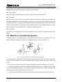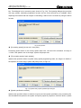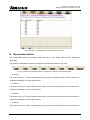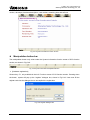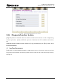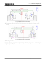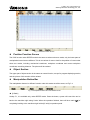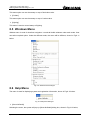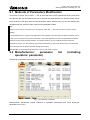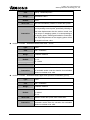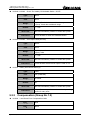
1
Weihong® Four Axes Engraving Machine’s Motion Control System Users’ Manual of Ncstudio V10 (Suitable For PCIMC-75A Control Card) July, 2010 Shanghai Weihong Electronic Technology Co., Ltd. 上海维宏电子科技股份有限公司 Weihong Electronic Technology Co., Ltd. Preface Thank you for choosing our products. This manual will help you acquaint with the product of our company and understand the information of system constitution and configuration and usage. It introduces the process of system installing and various functions. Before using this system, please read this manual in details. You will find it is beneficial for you to use it. For the hardware and software update continuously, it is possible that the software and the hardware you have received differ from the statement of this manual, for which we apology to you. Specialized, Concentrated, Focused i 上海维宏电子科技股份有限公司 Weihong Electronic Technology Co., Ltd. Attention: 1) Please don’t plug or pull out the cable connected with the computer when power on. 2) Please don’t plug or pull out the cable of Manipulation boxes when power on. 3) In order to guarantee safety and reduce disturbance, the shell of computer and engraving machine must be grounded. 4) When machine is not in use, please shut off the power. 5) Please pull out the BNC connector plugs, when the machine is not used for a period of time. 6) The spindle‘s life-span is inversely proportional to its rotation speed. 7) The engraver is very sharp, ban touching it in operation in case of injury .And also don’t contact it with handkerchiefs and scarves, in case of being involved to cause injury or damage equipment. ii Specialized, Concentrated, Focused 上海维宏电子科技股份有限公司 Weihong Electronic Technology Co., Ltd. Fast Master Chapter This chapter applies to the condition that all wires linking to electrical apparatus have been connected and the control card and Ncstudio system has been well installed. ¾ Check if the conjunction is correct. Test whether the communication signal is normal. Join the terminal board to port JP3 of the card with DB37M/F cable, add 24V power supply to the terminal board, and power supply for the machine signal system (proximity switch, etc). Examine signal input indicator LED on the terminal board: If the origin switch is normally closed, three LEDs of X0、Y0、Z0 should be alight. You can touch the origin switch through artificial imitation. (For travel switch, artificial pressure can be used to observe whether signals can be received. For photoelectrical switch, artificially obstruct the light to see if the signals can be gotten. For metal proximity switch, artificially touch it with metal to see if the signals can be gotten.) If the corresponding LED is out when being touched, it indicates that the origin signals have been sent to the terminal board. If the origin switch connected is normally opened, LED should be normally out, and by artificially touching the switch, LED will become light, which shows the origin signals have been received by terminal board. The same method can be taken to test other ports and to make sure the correctness of the wiring between terminal board and machine tool. This method can greatly shorten the debugging time. ¾ Debugging Signals Power on the computer, and then run Ncstudio. Open [Diagnoses]→[I/O Ports] window in which many mapping InPorts and OutPorts will be displayed. Dots in green indicate the signals are valid, while dots in red indicate the signals are invalid. Revise the polarity of the mapping InPorts according to the type of the origin switch, E-STOP buttons, and other selected buttons, etc. Polarity of the normally open InPort is “N”, and that of the normally closed InPort is “P”. After all modification has been finished, exit NcStudio software and restart it. Your modification will become effective. Supply power to the electrical box. Dots which are in front of signals of proceeding start, proceeding stop, tool calibration signal, zero points of the three axes and E-STOP InPort should be in red which indicate all these signals are invalid. If the dots show in green, you must examine the circuitry in electrical box and the polarity of the signals. If there is no problem with the circuitry, you have to revise the corresponding polarity to make sure the dots in front of the signals above show in red. Load processing program, open [AUTO] interface, press [Start] button, and observe if the color of the dots in front of [Program Start] changes. This dot should be in green when being pressed and in red when being released. If no change occurs to this dot, please turn to step one to check if LED on terminal board functions normally, check DB37M/F cable and make sure whether wiring conjunction of DB50M/F cable with the card and the terminal board. Imitate to touch the origin signals according to the first step. Check the reference point signals of X-axis, Y-axis and Z-axis. Once the origin signal is being touched, the signal dot should be in green. ¾ Set Parameters Set parameter [pulse equivalent] of manufacturer parameters. The smaller the pulse equivalent is, the higher the resolution is. But if the pulse equivalent is too small, it will influence the maximum feedrate. Users of model machine can generally set the pulse equivalent as 0.001 mm/P (The Specialized, Concentrated, Focused iii 上海维宏电子科技股份有限公司 Weihong Electronic Technology Co., Ltd. corresponding maximum feedrate is 9600 mm/min); After the pulse equivalent has been confirmed, please compute the electronic gear ratio of servo driver in accordance with value of this pulse equivalent. Electronic gear ration= encoder resolution × pulse equivalent × mechanical deceleration ratio/ pitch; Thereinto, mechanical deceleration ratio= reducer rotation speed input / rotation speed output= driven gear tooth number / driving gear tooth number. Move the machine manually, make sure the correctness of moving direction of each axis, be noted Ncstudio abiding by right-hand coordinates system. That is to say, rightward movement of X-axis is the positive direction, and upward movement of Z-axis is the positive direction, while the positive direction of Y-axis is to moving far away from the operator. (If Y-axis movement is the machine tool movement, the positive direction is the direction of machine tool moving towards the operator). If this direction is not right, you can revise [Axis Direction] parameter or relative servo driver parameter of manufacturer parameters. Set [table travel range] of manufacturer parameters on the basis of the actual machine tool dimension to make the software limit into function. Set [mechanical reference point] of manufacturer parameters on the basis of sensor installation position of the three axes, execute [back to the reference point] action, and carefully observe the moving direction of the axes when backing to the reference point. If moving direction is abnormal, you need to reset the parameters of [back to mechanical reference point]. Set transducer parameters, make it work under 0~10V analogue voltage control mode. Start /stop controlling adopts positive rotation terminal control mode. Press [Start] button in the software, observe in hardware port window whether the color of signal dot in front of spindle turns green, on the terminal board whether the corresponding green signal lamp LED of relay becomes light, and the spindle should start to rotate. If the spindle does not rotate, please examine the conjunction of transducer. Adjust spindle speed in the software and the rotation speed of spindle should be noticeably changed, otherwise, examine the conjunction and the parameters setting of transducer. If the spindle rotates in a wrong direction, please transform the conjunction between spindle and transducer: Usually, there are three wires joining with main spindle. Any two wires of them being exchanged will alter the rotary direction of spindle. ¾ Load processing File and Start Machining (or perform manual Machining) iv Specialized, Concentrated, Focused 上海维宏电子科技股份有限公司 Weihong Electronic Technology Co., Ltd. Contents 1 Summarization ........................................................................................................................... 1 1.1 Software characteristic ................................................................................................................... 2 1.2 Software Update Record ................................................................................................................. 4 2 System Installations .................................................................................................................. 5 2.1 The Basic Configuration of Ncstudio ............................................................................................ 6 2.2 Installation of Ncstudio ................................................................................................................... 6 2.2.1 Ncstudio Software Setup............................................................................................................ 6 2.2.2 Installation of Motion Control Card and Hardware Device ......................................................... 8 2.2.3 Other Installation Problems...................................................................................................... 11 2.2.4 Uninstall Ncstudio System........................................................................................................ 11 2.2.5 Connection between Ncstudio card and driver system............................................................ 11 3 The Basic Concepts of Ncstudio ............................................................................................ 12 3.1 Operation Mode and State ............................................................................................................ 13 3.1.1 Operation Mode........................................................................................................................ 13 3.1.2 Operation State ........................................................................................................................ 13 3.2 Machine’s Coordinate System...................................................................................................... 14 3.2.1 Machine Coordinate System .................................................................................................... 15 3.2.2 Workpiece Coordinate System................................................................................................. 15 4 Operation Interfaces of Ncstudio ........................................................................................... 16 4.1 Holistic Interface ............................................................................................................................ 17 4.2 Title Bar........................................................................................................................................... 17 4.3 Menu Bar......................................................................................................................................... 18 4.4 NC (Numerical Control) State Bar ................................................................................................ 18 4.5 Information Prompt Bar ................................................................................................................ 19 4.6 Function Window ........................................................................................................................... 19 4.7 Manipulation Button Bar ............................................................................................................... 20 4.8 Status Bar ....................................................................................................................................... 20 Specialized, Concentrated, Focused v 上海维宏电子科技股份有限公司 Weihong Electronic Technology Co., Ltd. 4.9 5 Operation Panel ............................................................................................................................. 21 Auto Mode of Ncstudio............................................................................................................ 22 5.1 Operation panel section ................................................................................................................ 23 5.2 Function panel section.................................................................................................................. 27 5.2.1 Position Function Section......................................................................................................... 28 5.2.2 Offset Function Section ............................................................................................................ 42 5.2.3 Program Function Section........................................................................................................ 48 5.2.4 System Function Section ......................................................................................................... 56 5.2.5 Parameter Function Section..................................................................................................... 59 5.2.6 Diagnosis Function Section...................................................................................................... 62 6 Manual Mode of Ncstudio........................................................................................................ 67 6.1 Operation Panel Section ............................................................................................................... 68 6.2 Function Panel Section ................................................................................................................. 71 7 Reference Point Mode of Ncstudio......................................................................................... 79 7.1 Operation Panel Section ............................................................................................................... 80 7.2 Function Panel Section ................................................................................................................. 81 8 Menu system of Ncstudio........................................................................................................ 84 8.1 File Menu ........................................................................................................................................ 85 8.2 Mode Menu ..................................................................................................................................... 88 8.3 Operation Menu.............................................................................................................................. 90 8.4 Machine Tool Menu........................................................................................................................ 94 8.5 Windows Menu............................................................................................................................... 95 8.6 Help Menu....................................................................................................................................... 95 9 Parameters of Ncstudio........................................................................................................... 97 9.1 Methods of Parameters Modification........................................................................................... 98 9.2 Manufacturers’ parameter list (including operators’ parameter) .............................................. 98 9.2.1 vi The general parameters of feed axis (Group No.1.0) .............................................................. 99 Specialized, Concentrated, Focused 上海维宏电子科技股份有限公司 Weihong Electronic Technology Co., Ltd. 9.2.2 Compensation (Group No.1.2) ............................................................................................... 101 9.2.3 Speed/ Acceleration limit (Group No.1.3)............................................................................... 104 9.2.4 The General parameters of spindle (Group No.2.0) .............................................................. 105 9.2.5 Tool magazine (Group No.3.1) ............................................................................................... 106 9.2.6 Tools (Group No.3.2) .............................................................................................................. 106 9.2.7 Lubrication (Group No.4.1)..................................................................................................... 108 9.2.8 Handwheel (Group No.5.2) .................................................................................................... 109 9.2.9 G code option (Group No.6.2)................................................................................................ 112 9.2.10 Track control (Group No.6.3).................................................................................................. 116 9.2.11 Speed control (Group No.6.4) ................................................................................................ 117 9.2.12 File translation (Group No.6.5)............................................................................................... 122 9.2.13 Tool change (Group No.6.6)................................................................................................... 128 9.2.14 Manual (Group No. 7.1) ......................................................................................................... 131 9.2.15 Auto (Group No. 7.2) .............................................................................................................. 133 9.2.16 Pause (Group No.7.3) ............................................................................................................ 135 9.2.17 Reference point (Group No.7.4)............................................................................................. 137 9.2.18 Measure (Group No.7.5) ........................................................................................................ 142 9.2.19 Other operations (Group No.7.9) ........................................................................................... 144 9.2.20 Position interface (Group No.8.1)........................................................................................... 146 9.2.21 Program Interface (Group No.8.3) ......................................................................................... 147 9.2.22 Diagnosis Interface (Group No.8.6) ....................................................................................... 148 10 Appendix of Ncstudio ............................................................................................................ 149 10.1 Appendix of shortcut keys.......................................................................................................... 149 Specialized, Concentrated, Focused vii 上海维宏电子科技股份有限公司 Weihong Electronic Technology Co., Ltd. viii Specialized, Concentrated, Focused 上海维宏电子科技股份有限公司 Weihong Electronic Technology Co., Ltd. 1 Summarization The software of Ncstudio, engraving machine motion control system, is independently designed by Weihong Electronic Technology Co., Ltd.. It can directly support G code, DXF format, PLT code format and ENG code of JDPaint processing file that are created by CAD/CAM applications such as UG, MasterCAM, CASMate, ArtCAM, AutoCAD, CorelDraw, and so on. Ncstudio takes the great advantage of 32-bit computing and multi-tasks. At the same time, its interface is simple and dependable. Apart from functions of auto mode, manual mode, MDI and backing to the reference point, this numeric control system can also do simulation, forecast processing time, load processing track in advance, dynamic track, remembering of breakpoints (program perform with skip segment), and rotor, etc. Specialized, Concentrated, Focused 1 上海维宏电子科技股份有限公司 Weihong Electronic Technology Co., Ltd. 1.1 Software characteristic Ncstudio system includes the following functions: Numerical rotary table control.(It may has difference in the different edition); Process automatically. Support G code, HP plotter (HP PLT format), DXF format and JDPaint (ENG format) of ISO standard; Manual function. You are allowed to control the machine tool not only by external input device, such as manual pulse generator, but also by input device of computer to complete manual operation, for example: keyboard, mouse and so on; Array processing, which can repeatedly perform the processing program according to rows and columns of array that the user selected; The function of incremental feed. It can be helpful for the users to set the amount of feed, and the length of stepping can be adjusted agilely; Special function of Manual Data Input. Users can input G command and execute it at once; Special function of process wizard. In order to complete functions of milling frame and milling bottom, what you need is to input several parameters; Support single block mode. User can set the program selected to be executed as [Single Block], which is a good way to support false diagnose and fault recovery action; Support advanced auto function of breakpoint memory and jump perform of program block; Support save / restore workpiece origin; Support the feed axis accurately returning to the reference point; Auto tool calibration function, which facilitates the users to a better processing procedure; Support feed ratio on-line adjustment. During the machining process, user can adjust the feed ratio at any time. The least value is “0” that indicates the processing is suspended, and the maximum ratio is 120%; New function for high-smooth speed connection algorithm. In a usual numerical control system, connection speed between two G codes commonly is a fixed value (e.g., it may be 0 or a certain small fixed value). However, in new version of NC system, it adopts a particular adaptive prediction algorithm of processing speed. In accordance with speed value, direction and maximum acceleration, and the function of forward prediction, the algorithm adaptively decides the connection speed between the current instruction and the next instruction. It has greatly increased the processing efficiency (efficiency enhancement ranges from 30% to 300%) and improved the processing capability that has eliminated the speed chatter marks left on the processing surface; Particular function of two-dimensional mimic display. By simple operation, you can observe the 2 Specialized, Concentrated, Focused 上海维宏电子科技股份有限公司 Weihong Electronic Technology Co., Ltd. processing result from different angles to understand the processing result more accurately and more intuitionally; New function of loading processing track in advance. After loading the processing file, system will automatically analyze and output the processing tracks. User can directly call out the tracks to view; Simulation function. This application can rapidly simulate the machining process for the program and will finish it in a short time. In the mean time, it can check if there are any mistakes with the program and if the processing result can meet your satisfaction, and can count precisely the actual processing time; Support keyboard operation. To satisfy user’s need, we offer a strong support to the keyboard operation in the new version; Log function. The system has a strong Log function which is very helpful for the user to view the detailed processing information and system diagnoses; Special enclosed processing file manager. And user needs to save the processing file to a specified directory; Ncstudio can administrate the processing file in an enclosed file manager. Support enclosed processing file editor. Any time user can introduce processing file into file editor to edit and modify it; Support to display the file processing information. By simulation or actual processing, [file processing information] window can help users to count some important information, such as processing time, processing range, the amount of finished workpiece, etc; Particular [Parameters Auto backup] function. System can automatically save the parameters setting information which can save a lot of time to set parameters time and time again. Support 8 parameters setting backup in [Parameters Back Up] window. Users can save different parameters setting of different processing file, and can load it at any time; Particular [I/O Port] window can do map simulation, test and regulate polarity. Users can well realize hardware detection, processing supervision, and fault diagnoses; New function of PLC module, by which you can control I/O port; Support intelligent prediction; system will analyze situation in the forward or backward distance, to decide interpolation strategy and improve the integral smoothness of workpiece; Support MPG (Manual pulse generator), user can determine whether to use MPG or not according to their needs; Support multi-language, currently, English and Chinese are embedded in the software, other languages will be added in demands; Proper parameter setting, it can improve machining efficiency on the basis of ensuring accuracy; Support NCE format, it’s simple to make machining files. Specialized, Concentrated, Focused 3 上海维宏电子科技股份有限公司 Weihong Electronic Technology Co., Ltd. 1.2 Software Update Record In order to make it swifter for users to grasp our software update information, we list the update records of all versions of software. With comparison between received software version and this record, users can update software promptly. If users need special customized function, please contact us. Improve the degree and stability of simulation; User can test “Back to Mechanical Origin”, save Mechanical Origin, and also add stroke range, limit position in simulating window during simulating. New Added Function: System maintenance; Users can maintain system by themselves, and also make setup package for steady system with entire parameters. Enhanced Function: Icons in [I/O Port] interface vary with different state; the interface has been further optimized. New Added Function: Under auto mode, some information will be displayed in information window under [Position] section, such as [Workpiece Counting], [Cutting Time] and [Processing Time]. Strengthen Function: We have appended a timer and a counter for advanced user in [PLC] Window Encryption limit on hardware to protect user’s right; Newly add encoder zero signal, servo driver alarm signal and servo driver enabled signal. 4 Specialized, Concentrated, Focused 上海维宏电子科技股份有限公司 Weihong Electronic Technology Co., Ltd. 2 System Installations It is very simple to install Ncstudio application. Advanced users or those who have been familiar with the application can refer to our instruction of fast master installation. Specialized, Concentrated, Focused 5 上海维宏电子科技股份有限公司 Weihong Electronic Technology Co., Ltd. 2.1 The Basic Configuration of Ncstudio Host computer CPU: main frequency 1G or above. Memory: 512 M or above. Hard disk: 20G or above. Display adapter: 1024*768 at least Display: 14" VGA or above CD-ROM: 4X or higher Mainboard Expansion Slot: More than 2 slots of PCI 2.2 Installation of Ncstudio If there is already old version of Ncstudio, please delete it, and then install the new version. Regarding how to delete the old version, please turn to chapter of uninstall procedure. Ncstudio includes two parts: the software and motion control card. So, the setup of the system is also divided into two stages: The software setup and the motion control card setup. Please complete the installation of the software before installing the motion control card. In this way, driver for the motion control card needn’t be separately installed. Following instruction does not include installation of electrical equipments, and please refer to “Manufacturer Manual” for detailed information. 2.2.1 Ncstudio Software Setup Software installation can be divided into several steps as following: Power the computer, start up the computer to enter into the operation system automatically. Put the setup CD of Ncstudio system into the CD-ROM .Double click the “My computer" icon, then double click the CD-ROM icon. Find out the SETUP.EXE file and double click its icon . The first dialogue box that appears is the [Language theme] dialog, see Fig.2-1. In V10 version, you can switch over between English and Chinese. If you click [Chinese], run Ncstudio system after installation, the system will take the Chinese interface as the default interface. For the same reason, if you click [English], the system will take the English interface as the default interface. Besides, users can also switch language in [System] window. If there is already Ncstudio on the computer, the new package will delete the old version and install the new version to update the software. At this time, an update prompt will appear on the screen, shown in Fig.2-2. 6 Specialized, Concentrated, Focused 上海维宏电子科技股份有限公司 Weihong Electronic Technology Co., Ltd. Fig. 2-1 Installation Language Selection Dialogue Box Fig. 2-2 Update Prompt Dialogue Box Click [Yes (Y)]. In order to avoid disturbance, system will ask user to save parameters and delete the old version before going on further installation. Shown in Fig. 2-3 is the prompt to save parameters before installation. Fig. 2-3 Saving Parameters before Installation Click [Yes (Y)]. Installation begins. Ncstudio will be installed to the default directory, C:\Program Files\Naiky. Installation progress bar will show you the installation speed. See Fig.2-4. After installation, prompt will remind user whether to shut down the computer (We recommend to close the computer, and then to install the control card. See Fig.2-5. Specialized, Concentrated, Focused 7 上海维宏电子科技股份有限公司 Weihong Electronic Technology Co., Ltd. Fig. 2-4 Software Installation Interface Fig. 2-5 Whether to close the computer at once (suggest operation: Yes) Here we have finished the software installation. 2.2.2 Installation of Motion Control Card and Hardware Device Installing Ncstudio motion control card is divided into the following steps. Close the host machine’s power supply, open the cover, and insert the motion control card into an empty PCI expansion slot. While installing the motion control card, lightly press two flanks of the motion control card, make sure the motion control card is firmly inserted into the slot, and get in well touch with computer baseboard, dependably without fluttering, then tighten the locknut of the card and finally lid the cover. The installation of control card is completed. 8 Specialized, Concentrated, Focused 上海维宏电子科技股份有限公司 Weihong Electronic Technology Co., Ltd. Similar to the installation of the control card, please insert peripheral equipments into the corresponding slots or ports and make sure it is firmly fixed without fluttering. After the installation of motion control card and other peripheral equipments has been finished, please restart the computer. The operation system will report a new hardware has been found, and pop up a hardware update guide dialog. See Fig.2-6. User should choose [No, not at this time] and click [Next] to go to next page. See Fig.2-7. User should choose [Auto Install the Software] and click [Next]. See Fig.2-8. Then the operation system will install the driver application for Ncstudio software. Then the whole installation of Ncstudio software and the motion control card has been completed. To start Ncstudio software, click [Start] menu on the desktop →click [Applications] →click [Ncstudio]. And you can also start it by other shortcuts. Fig. 2-6 Page one of the Hardware Update Guide Specialized, Concentrated, Focused 9 上海维宏电子科技股份有限公司 Weihong Electronic Technology Co., Ltd. Fig. 2-7 Page Two of Hardware Update Guide Fig. 2-8 Page Three of Hardware Update Guide 10 Specialized, Concentrated, Focused 上海维宏电子科技股份有限公司 Weihong Electronic Technology Co., Ltd. 2.2.3 Other Installation Problems If you don’t obey the above installation procedure and insert the motion control card before software installation. The computer will remind you to install driver for motion control card installation. Please cancel the dialog of installing driver, and directly install Ncstudio software, restart computer and the operation system will request once again to install driver for the motion control card, at this time you can set according to the hardware guide of the last chapter. After all installation has been finished, you can start to use Ncstudio software. 2.2.4 Uninstall Ncstudio System Ncstudio is green software and has the advantage of easy installation and no need to write installation information into registration form. And it’s convenient to uninstall, which is portable and can be copied to floppy disk for running. Besides, to uninstall Ncstudio system, customers only need to directly delete its document folder: C:\Program Files\Naiky, delete [Start] menu→ [Applications] → NcStudio, and also the shortcut on the desktop. When new version of Ncstudio is installed, the old version will be auto refreshed and overlapped. 2.2.5 Connection between Ncstudio card and driver system The mechanical motion control signal of Ncstudio is passed by motion control card inserted in PC expansion slot, communicating with motor driver system in electrical box of Machine tool. Before connection of Ncstudio card and motor driver system, the electrical box should be installed on machine by exclusive cable, connecting the related socket on motion card. Then connection is ended. Notice: Please refer to the card manual of concrete type for wiring diagram between card and electrical system. The working method may be different for different type, and the functions may also vary. Specialized, Concentrated, Focused 11 上海维宏电子科技股份有限公司 Weihong Electronic Technology Co., Ltd. 3 The Basic Concepts of Ncstudio Ncstudio is a comparably complicated system which refers to many concepts, such as workpiece coordinates system, Mechanical Coordinates System, operation mode, operation state and so on; unavoidably the user will use these concepts. Therefore, the user must understand the concepts before using the newest edition. 12 Specialized, Concentrated, Focused 上海维宏电子科技股份有限公司 Weihong Electronic Technology Co., Ltd. 3.1 Operation Mode and State 3.1.1 Operation Mode Regarding users’ operation to the machine tool, there are several operations mode as below. And it’s very important to comprehend operation mode for correct operation. Auto Mode Under automatic operation mode, the machine tool generates motions through the procedure loaded in advance. So the processing procedure must be loaded. Manual mode Manual mode can be divided into [Jog] mode and [Stepping] mode. ¾ Under [Jog] mode, users can control the machine tool by manual operation equipments, such as keyboard, hand impulse generator and hand control panel, etc. when user sends motion signal by these devices, for example, keep pressing the button on software, the machine will keep in motion until the manual button is released. ¾ Under [Stepping] mode, users also use manual operation device to control machine, e.g. impulse generator, keyboard and hand control panel, but the situation is different from [Jog] mode. When users press the key once and the machine will move a specified distance until the manual button is released. So the displacement of the machine can be accurately controlled under this mode. Reference point mode (Back to the reference point) Under reference point mode, [Back to the Reference Point] is available. 3.1.2 Operation State In terms of the motion mode of the machine tool, each operation mode can be divided into the following types of operation states; it is operation mode and operation state that decides the state of a machine. IDLE State Idle state is the most common state. Under this state, the machine has no motion to output, and is always prepared to accept any new task. ESTOP State This is an abnormal state. When there is a hardware fault or when user presses down the [Reset] button, system will enter ESTOP state and implement the predetermined protection actions, such as closing spindle motor and cooling pump. In this state the machine tool is locked and cannot carry out Specialized, Concentrated, Focused 13 上海维宏电子科技股份有限公司 Weihong Electronic Technology Co., Ltd. any new motion. After hardware fault or ESTOP state is obviated, system will automatically implement [Reset] action and make the machine tool return to the IDLE state. Running State When the machine is implementing any action, system enters into Running State. Pause State When a machine tool is running, if user performs [Pause] command, or presses down [Pause] button, or system parses a M01 command (waiting instruction), system will enter into PAUSE state and wait for further instruction. To suspend the current action and let the system enter into IDLE state, several methods can be effective. For example: Perform ‘Start’ command, or press [Start] button, or perform ‘Stop’ command, or press [Stop] button, or press [Auto mode] or [Reset]. LOCK State Lock state is an internal state which occurs in switching states. And User normally won’t meet this state. 3.2 Machine’s Coordinate System Coordinate system is a terminology that is used to describe the motion of the machine tool. For the sake of unification, Standard coordinate system adopts the right-hand rule. See Fig.3-1. Fig. 3-1 The Right Hand Principle of Standard Coordinate System For milling machine, the direction of machine axis is decided by both the type of machine tool and the layout of each component. The basic coordinate axes of milling machine are X-axis, Y-axis, and Z-axis: ——The direction of the cutter moving away from workpiece is the positive direction of Z-axis (Z+). ——X-axis is perpendicular to Z-axis and parallel to the clamped surface of workpiece. For the single column vertical milling machine, if user faces the spindle and looks in the column direction, right moving direction is the positive direction of X-axis (+ X). ——X-axis, Y-axis and the Z-axis constitute the coordinate system adhering to the right-hand rule. 14 Specialized, Concentrated, Focused 上海维宏电子科技股份有限公司 Weihong Electronic Technology Co., Ltd. 3.2.1 Machine Coordinate System Machine coordinate system is a set of fixed right-hand coordinate system. Its coordinate origin is a fixed position that corresponds to the machine tool. Therefore, at any time, a certain point in space can be exclusively fixed by machine coordinate system. The machine coordinate system requires the machine being available of function of [back to origin], or this term will only appears in the software. 3.2.2 Workpiece Coordinate System It is more often to adopt workpiece coordinate system at machining various kinds of workpieces. Generally speaking, the machining position that we mention is a certain point relative to the workpiece, while the position where the workpiece is clamped is always variable corresponding to the machine origin, so it is necessary to introduce a set of more convenient coordinate system for workpiece machining. That is workpiece coordinate system. Workpiece coordinate system adheres to the right-hand rule as well. Its origin is fixed corresponding to a certain point on the workpiece, and is possibly floating corresponding to the reference point. Specialized, Concentrated, Focused 15 上海维宏电子科技股份有限公司 Weihong Electronic Technology Co., Ltd. 4 Operation Interfaces of Ncstudio Operation interfaces of Ncstudio are constituted by seven major sections. They are title bar, menu bar, numerical control state bar, information display bar, function window, status bar, and operation bar. Compared to the previous each version, this version has great changes in the operation interface. z Picture display is more intuitional and detailed. Tracks can be shown under every operation mode. All processing demonstration is visible in the coordinates screen. The accuracy and instantaneity of the processing view is ensured to the highest degree. z The system provides Powerful visual function, friendly interface, distinct style, and stylish interface pattern. You can freely select the theme of interface or design by yourself. z Add the button tip function. When user moves the mouse to a button, a hovering tip will appear to tell you the button’s function or its shortcut key. z Add the simulation operation panel function. The rich modes to be selected can satisfy users’ different requirements. z Single shortcut key mode makes the operation easier. 16 Specialized, Concentrated, Focused 上海维宏电子科技股份有限公司 Weihong Electronic Technology Co., Ltd. 4.1 Holistic Interface The main operation interface of NcStudio is shown in Fig.4-1 below. Function Selection Button Subfunction Switch Button Mode Selection Button Manipulation Button Bar Fig. 4-1 The main operation Interface 4.2 Title Bar The first column of NcStudio software interface is the title bar, shown in Fig.4-2. It is used to show the name of the application and the name of the loaded processing file. The color of title bar indicates whether the corresponding window is activated or not. Fig. 4-2 Title Bar Note: An active window refers to the window which can accept the input of keyboard at present. Anytime only one window can be active, and all the other windows are inactive. Please pay attention to the different color of the title bar between the active window and inactive window. The color of the title bar of an active window is blue, while that of inactive windows is grey. Click the right mouse button or press shortcut “Alt + spacebar”, and a system menu will pop up. This menu can control the position and the size of the window, such as restore, move, and close, maximize, minimize, etc. On the right side of the title bar, there are three control buttons, including button for restoring, button for maximizing and button for minimizing. These buttons are used for quickly setting the size of the window. Specialized, Concentrated, Focused 17 上海维宏电子科技股份有限公司 Weihong Electronic Technology Co., Ltd. 4.3 Menu Bar Under the title bar is the menu bar, see Fig.4-3. Fig. 4-3 Menu Bar The menu bar is composed of several pull-down menus, including multi-menu items; each menu item can realize a special function, action, or state that is relative to a certain procedure. And the menu item can be selected by mouse or keyboard. Inside of the Ncstudio menu bar, there are menu of file, mode, operate, machine tool, windows and help, through which users can conveniently implement the action of processing file, mode selection, machining operation, machine relative operation, windows exchange, getting help information, etc. Mouse operation Firstly, left click the menu on the menu bar, a pull-down menu will pop up, and now once again left click to choose your target item. Keyboard operation Simultaneously press down ‘Alt’ key and hot key of the letter corresponding to the menu selected (For example, there is a line under ‘F’ in the “file” menu, so the combination key is “ALT+F”), after which a relative pull-down submenu will pop up. Regarding the item in the pull-down submenu, you can also take the keyboard operation to choose your target item. For instance, [File] → [Open and Load].When the pull-down menu of [File] appears, directly press the letter ‘O’ to open the process file. Shortcut key operation In the pull-down submenu, there are relative shortcut keys at the right of some menu options. For example, [File] → [Open and Load], the shortcut key is ‘Ctrl + O’. That is to say, you can directly execute the corresponding action which can avoid the trouble to enter into multilayer menu. Some menu option has three dots behind. For example, [File] → [Open and Load…], it indicates that a dialog will automatically pop up. If the item of the submenu shows in grey, it indicates that the item is unavailable under the current state. In addition, right click on different position, a corresponding shortcut menu will pop up, then choose the relative item to perform your command. 4.4 NC (Numerical Control) State Bar Under the menu bar is the NC (Numerical Control) state bar, see Fig.4-4. Fig. 4-4 The NC State Bar 18 Specialized, Concentrated, Focused 上海维宏电子科技股份有限公司 Weihong Electronic Technology Co., Ltd. The embedded prompt boxes on the NC state bar range from operation mode, operation status, other appended information, and configuration information. In the middle-right is the processing time. It gives the user an intuitional way to get the current machine state and the processing time, as Fig.4-4. 4.5 Information Prompt Bar Under the NC (Numerical Control) state bar is the information prompt bar, see Fig.4-5. Fig. 4-5 the information prompt bar On the prompt bar, three kinds of information can be shown. They are normal prompt information, warning prompt information and error prompt information. Note: The normal prompt information is mainly distinguished by color of characters on information prompt bar. In the grey theme, if the color of the prompt bar is the same as the color of the current interface and the inside characters show in black, which indicates the current prompt information is the normal prompt information; If the color of the prompt bar is yellow and the characters show in deep black, the current prompt is the warning prompt information; If the color of the prompt bar is red and the characters show in white, the current prompt is the error prompt information. In the black theme, if the color of the prompt bar is the same as the color of the current interface and the inside characters show in white, the current prompt information is the normal prompt information; If the color of the prompt bar is yellow and the characters show in deep black, the current prompt is the warning prompt information; If the color of the prompt bar is red and the characters show in white, the current prompt is the error prompt information. 4.6 Function Window Function window is the main component of Ncstudio V10 interface. It is used to display different kinds of function screens, including six powerful function section and button column of screen manipulation, such as [Coordinate], [Offset], [Program], [System], [Parameter], and [Diagnose]. And user can press down the [function selection button] (see Fig.4-6) to enter into the corresponding function section. Fig. 4-6 Function Selection Button Each function section has its relative subfunction. For example, under the [Offset] function section, there are subfunctions of [workpiece coordinates], [offset], [save & load]. Under the [Program] function section, there are screens of [HD List], [ProcessWizard] and [History record]. To exchange between function screens, please press the [subfunction exchange button]. See Fig.4-7. Specialized, Concentrated, Focused 19 上海维宏电子科技股份有限公司 Weihong Electronic Technology Co., Ltd. Fig. 4-7 Subfunction exchange button 4.7 Manipulation Button Bar Under the function window is the manipulation button bar, see Fig.4-8. Fig. 4-8 The Manipulation Button Bar What it usually shows is the shortcut button relating to the current function screen or the current mode. For instance, under the function screen of [Program]→ [HD List], the manipulation button column has buttons of [load], [Unload], [breakpoint resume], [simulation], [selected machining], [Handwheel guidance] and [Back to origin], etc. Users can choose the manipulation button to do the relevant operation following the content displayed on the function screen. Note: Unless the conditions are satisfied, some buttons in the manipulation button column is banned to prevent false operation. V10 Ncstudio are specially setting the operation mode of single shortcut key, it will show the single key hint on [subfunction exchange button], [function selection button], [mode selection button] and other operation button. What the user needs to do is to press down the prompt key, and then the system will have a relevant response. [Position (W)] button as an example, what the user needs to do is to press down the [W] key of the keyboard, then it can jump to the corresponding window. The default single shortcut key, [Function selection button], ranges from 1 to 6; The default single shortcut key, [Mode selection button], ranges from 7 to 9; The default single shortcut key, [subfunction exchange button], ranges from left to right order of Q, W, E, R, T, Y; In the [position] function section, there are some parameters settings under [setting] function section, which can adopt system default shortcut keys H、J、K、L、U、I、O. On the operation panel , B, N, M are the single shortcut keys of the ratio slide, these three keys can make the focus transferring to the rate slide button, which can be operated by the button of Page Up /Page Down. If you are familiar with the operation of the single shortcut key, you will not only make the operation process easier but also save much time! 4.8 Status Bar The status bar is at the bottom of the screen. See Fig.4-9. At the lower right of the status bar is a prompt of keyboard lock which is used to show you the current date, the current time, and the current state of the capital lock, the number lock, and the scroll lock. 20 Specialized, Concentrated, Focused 上海维宏电子科技股份有限公司 Weihong Electronic Technology Co., Ltd. Fig. 4-9 The status bar 4.9 Operation Panel According to the mode differences, the operation panel can be divided into automatic mode, manual mode and reference point mode, as Fig.4-10. Above the operation panel, there is coordinates displaying section where you can see the workpiece coordinates and the machine coordinates, the current feed speed, the current spindle rotation speed and the name of the current loaded file. Under the coordinates displaying section is the panel button area. Buttons inside this panel button area will be different under different mode. Fig. 4-10 The Operation Panel Specialized, Concentrated, Focused 21 上海维宏电子科技股份有限公司 Weihong Electronic Technology Co., Ltd. 5 Auto Mode of Ncstudio In auto mode, system can automatically analyze loaded processing program to control the machine tool on machining the object workpiece. The advanced function can be fulfilled that breakpoint resume, selection processing, handwheel guidance. 22 Specialized, Concentrated, Focused 上海维宏电子科技股份有限公司 Weihong Electronic Technology Co., Ltd. The picture of auto mode is shown in the Fig.5-1, including operation panel and function panel, which will be introduced in detail. Function Panel Operation Panel Fig. 5-1 Auto operation mode 5.1 Operation panel section This panel consists of buttons for auto operation of the machine, supporting an alternant operation environment for manipulating machine tool automatically. See Fig.5-2. Specialized, Concentrated, Focused 23 上海维宏电子科技股份有限公司 Weihong Electronic Technology Co., Ltd. Fig. 5-2 Auto Operation Panel Dialogue On the top of the panel, there is a coordinate display zone, which displays the current coordinate of x-axis, y-axis, z-axis and a-axis, feedrate and the name of current file. Under the mini coordinate display area is the panel button area, inside which buttons are different under different modes. Under Auto mode, button zone includes the following contents: [Feedrate ratio sliding button] Shown in Fig.5-3: Fig. 5-3 Feed Ratio Sliding Button Dialogue User can manipulate the feed speed by controlling the feedrate. The formulation is as following: Current feed speed = rated feed value * current feedrate. The least unit of feedrate is 10% (every grid is 10%). Current feedrate percent is displayed beneath the word “Feedrate”. Three ways can be used to revise feedrate percent. Click on the sliding axle; Drag the slide block; Click the slide block to choose it, then press [PageUp], [PageDown] key; Each time press [PageUp] or [PageDown] key, the block moves one case, and the feedrate increases ( decreases) 10%. The range of Feedrate percent is 0% ~ 120%. 24 Specialized, Concentrated, Focused 上海维宏电子科技股份有限公司 Weihong Electronic Technology Co., Ltd. [Spindle rate sliding] Shown in Fig.5-4: Fig. 5-4 Spindle Rate Sliding Button Dialogue User can control the spindle speed by adjusting the current feed rate. Its calculating expression is: current spindle feed speed = current spindle rate * spindle speed. The least unit of feed rate of the sliding axle is 10%, the axle will give prompt about percentage below the word “Feed rate” after adjust. User can control the sliding axle by mouse or keyboard method. Mouse method: click the left key of mouse on the sliding axle, or draggle the block of the sliding axle. Keyboard method: pressing down the Page Up (Page Down) key of function-keyboard, pressing down the key one time, the rate increases (decreases) 10%. The range of spindle ratio is 50%~ 150%. [G00 ratio sliding button] Shown in Fig.5-5: Fig. 5-5 G00 Ratio Sliding Button Dialogue User can manipulate the G00 spindle speed by adjusting the G00 ratio. When G00 ratio is adjusted to 0%, the actual G00 ratio is equal to the feed rate, and the sliding axle will give the prompt “G00 ratio= Feedrate” below the word “G00”. Its calculating expression is: current tool moving speed under G00 instruct = current feed rate * processing speed. When G00 ratio is not equal to 0%, its calculating expression is: current tool moving speed under G00 instruct = G00 rate * dry run speed. The least unit of G00 ratio of the sliding axle is 25%, the axle will give prompt about percentage below the word “Feed rate” after adjusting. User can control the sliding axle by mouse or keyboard method. Mouse method: click the left key of mouse on the sliding axle, or draggle the block of the sliding axle Keyboard method: pressing down the Page Up (Page Down) key of function-keyboard, pressing down the key one time, the rate increase (decrease) 25%, the range of Feed rate sliding axle is 0% ~ 100%. [spindle on], [spindle off], [coolant on], [coolant off], [lubrication on], [lubrication off] Specialized, Concentrated, Focused 25 上海维宏电子科技股份有限公司 Weihong Electronic Technology Co., Ltd. Shown in Fig.5-6: Fig. 5-6 the Start/Stop Button Dialog of Spindle, Coolant Valve, and Lubrication Valve on Operation Panel These buttons respectively control the switch of spindle, coolant valve, and lubrication valve. On the front row is the start button, there are character prompts on the upper of the button, when the button is pressed down, the back ground of the button is green. On the back row is the close button, there are character prompts on the upper of the button, when the button is pressed down, the back ground of the button is red. Under the mode of auto, manual, MDI, and reference point, the operation panel displays all the start / stop buttons, and the function differs from each other under the different mode. [Start] Shown as Fig: . The shortcut key is F9, which is only available under auto mode. ¾ If user doesn’t load the processing file, the button is disabled; ¾ If user loads the processing file and accomplishes the going back to the mechanical origin operation, the button is valid. Pressing down the button, system will start processing automatically. ¾ If user hasn’t finished the reference point operation (“back to mechanical origin” or “directly setting”) in loading the file for the first time, the system will prompt to go back to the mechanical origin after pressing this button. This button has two functions: ¾ First: If a certain processing file has been loaded after finishing reference point operation and the current system state is "idle", pressing down the button, machine tool will carry out the processing procedure automatically from the first section. Once starting the process, the system will enter the status of “Auto/ run”. If the system is in the status of simulation, the system starts to simulate. ¾ The second: If the system is placed in the “auto| pause" state, processing down the button, the system will carry out continuously from the pause into “auto| run". If the system is in the status of simulation, the system starts to simulate. [Pause] 26 Specialized, Concentrated, Focused 上海维宏电子科技股份有限公司 Weihong Electronic Technology Co., Ltd. Shown as: . In automatically processing, the "pause" button is valid. Pressing down the button, the machine tool will pause and raise the cutter and then turn to the state of “Auto/pause”. And then if user wants to keep on processing, you can press down the button “start”. If the system is in the status of simulation, pressing down the button, simulation will be paused and then turn to the state of “Auto/pause”. If user wants to keep on simulating, can press down the button “start”. Shortcut key: F10, only available for AUTO mode Note: System has two ways to enter [Pause] state: 1. When system is executing single block function; 2. User selects [Pause] function during machining process. [Stop] Shown as: . This function is enabled under the auto mode or the input of G code by users. Pressing down the button, the machine will be stopped and raise the tool, and then terminate the whole assignment, the system enters the state of “Auto/idle”. This method is to break off the processing program normal in processing. Shortcut key: F11, only available for AUTO mode or the state that G code is entered and running. [Reset] Shown as: . The button is valid under all circumstance. Pressing down the button, the machine tool will recover the state from warning to idle (if the system is in the state of warning) and terminate the whole assignment peremptorily (if the machine tool is processing). Different from stop function, [Reset] button terminates machining with E-stop, but spindle’s state and cooling will not be changed, there is no deceleration and no spindle uplift. Shortcut key: F12, available for the entire mode. 5.2 Function panel section Under auto mode, the function panel buttons are as following, see Fig.5-7: Fig. 5-7 Coordinate function buttons of auto mode Specialized, Concentrated, Focused 27 上海维宏电子科技股份有限公司 Weihong Electronic Technology Co., Ltd. 5.2.1 Position Function Section Under AUTO mode, [POS] subfunction section includes: Normal, Pos, Track, Prog, Info, and Setting. See Fig 5-8 below: Fig. 5-8 Subfunction exchange button of [position] in Auto mode z Normal function screen Normal function screen, see Fig.5-9 Fig. 5-9 Normal Function Screen In the process track window, the path of the tool is tracked in real time. User can directly check tool’s track and make sure the machining procedure executed accurately. Besides, in two-dimension track mode, NcStudio supports abundant operating method to give user facilities to look over the process figure from different position and scaling, such as zoom in, zoom out, etc. [Icon Button] On the left of the process track window, there are icon buttons, see Fig.5-10. V10 NcStudio adds a tip function for each of these icon buttons. Move mouse onto the button, a tip will display. It tells user the button’s function. ¾ [Move]: By dragging operation of the mouse’s left key can move the tracking figure; Click the icon ( 28 ), Specialized, Concentrated, Focused 上海维宏电子科技股份有限公司 Weihong Electronic Technology Co., Ltd. move mouse to the display window, the mouse shows mouse shows , clicking the left key of the mouse, the , drag the mouse slowly, and loose it after completing the moving of the whole track figure. User can also implement this function by keyboard. When the move icon button was pressed down, press the enter key, and then press the direction key to move the whole track figure. When the mini-keyboard is unlocked, the mini-keyboard can be used as direction key. Note: The operation is very convenient. User can greatly raise their working efficiency if practice perfectly. Fig. 5-10 Shortcut Iron Button on the Left of the Processing Track Window ¾ [Zoom In] Click the and [Zoom Out] [Zoom in] or [Zoom out] button on the left of the process track window, then move the mouse into the display area, when the mouse shows enlarge the figure, when the mouse shows , click the left key of the mouse to , click the left key of the mouse to reduce the figure. Shortcut: on mini-keyboard, [-] key can zoom out the figure and [+] key can zoom in the figure, no matter whether the mini-board is locked or not. Notice: When the track view is zoomed in or out by mouse, it can be partly enlarged or reduced, user only needs to select the area by mouse. Specialized, Concentrated, Focused 29 上海维宏电子科技股份有限公司 Weihong Electronic Technology Co., Ltd. If the track view is enlarged to the limit, the view will be automatically switched to [zoom in] mode. If the track view is reduced to the limit, the view will be automatically switched to [zoom out] mode ¾ [Show Current Processing Point]: Click [Show Current Processing Point] on the left of the process track window. The current processing point will be display in the center of the display window. Shortcut key: [End] key on the keyboard. ¾ [Adjust to Window Size]: Click button [Adjust to Window Size] on the left of the process track window. The process track window will adjust to display all the paths and make path center in its midpoint. With this method, customer can see the whole figure and needn’t drag the scroll bar.Shortcut key: [/] key on the keyboard. ¾ [Clear/Delete]: After a long time of machining, the simulation figure becomes very complex and the temporary folder used to record processing path becomes more and more bulkiness. It will spend a lot of time at redrawing, moving, or revolving the simulation figure. At this time, user needs to clean the tracking window. The actual processing track is cleared after pressing the button. Click the [Clear] button on the left, the simulation figure in the processing track window will be deleted. Shortcut key: [Delete] key on the keyboard. View button group, as shown in Fig.5-11 below: Fig. 5-11 View Button Group This group of buttons is used to observe the angle of view of track, when user moves the mouse to the group of buttons and a hovering tip will appear to tell user the corresponding angle of view. User 30 Specialized, Concentrated, Focused 上海维宏电子科技股份有限公司 Weihong Electronic Technology Co., Ltd. can choose a suitable angle of view to observe the processing track, this can be more convenient for user to observe processing cutter path, and detect processing state. When user moves the mouse to the track window and a hovering tip will pop up—shortcut key: s, when user press down S key, the system will pop up the view navigator, as shown in Fig.5-12 below, at this moment the user can operate it according to the single shortcut key on the navigator. S: front view; W: top view; X: bottom view; A; left view; D: right view; Q: northwest view; E: northeast view; Z: southwest view: C: southeast view. Fig. 5-12 View Navigator Shortcut menu Click the upper track window of the general window with the right key of mouse, and user can execute the related operation on the pop-up menu. As shown in Fig.5-13 below: Specialized, Concentrated, Focused 31 上海维宏电子科技股份有限公司 Weihong Electronic Technology Co., Ltd. Fig. 5-13 the Shortcut Menu of the Track Window The function of these quick menus will be illustrated separately as following (the above icons with the same function will be omitted) ¾ [Clear] There are many methods to clear the tracking window. You can complete it by menu, toolbar button, hot key, and the keyboard. Menu method: choose the menu of "Edit (E)| Clear View (C)" Hot key method: Press down the key of “CTRL+ DEL” to realize the clearance of track window Mouse method: Move the mouse into the manifestation area, click the right key of the mouse, then a menu will pop up, chose the option of “Clear”. Keyboard method: Press the key of Delete while the trace window is current active window. ¾ [Center] Show current machining scope in the center of the machining track window. Menu method: Choose "View|Center View" on menu to perform. Mouse method: right click in the window, a context menu will flip out, choose" in the center" option. Keyboard method: first, activate this window, press "Home" key on the keyboard. Shortcut key method: press “Home” key on keyboard, or right-click to pop up quick menu and then press “N” key 32 Specialized, Concentrated, Focused 上海维宏电子科技股份有限公司 Weihong Electronic Technology Co., Ltd. ¾ [Property] Click [property (M)] button on shortcut menu, the system will pop up [individuation parameter] dialogue, shown in Fig. 5-14 below, this window is used to customize track window to set track mode and color: Fig. 5-14 Property Dialogue Box Click each color button, and you will see the following color selection box, as Fig.5-15. Fig. 5-15 Color Selection Dialogue [Track Color] In the track window, you can allocate each different display elements respectively. Include: Color of G00 instruction: This color indicates the color of G00 instruction’s track. Color of G01 instruction: This color indicates the color of G01 instruction’s track. Color of G02 instruction: This color indicates the color of G02 instruction’s track Color of G03 instruction: This color indicates the color of G03 instruction’s track Another, Jog and manual mode are shown in color of G01. [Background color] Background color of track window has two kinds of colors, and user can collocate two kinds of colors Specialized, Concentrated, Focused 33 上海维宏电子科技股份有限公司 Weihong Electronic Technology Co., Ltd. and realize two kinds of colors changing gradually. [Gridding Color] It indicates the gridding color in track window. [Coordinate Color] It is the color of the coordinate and worktable boundary shown in the Track window. Prompt: If the color of the command you selects is transparent, the command will be concealed. If the background color is set as transparent, the track window will not be rightly shown, so user must be serious to select “transparent” color. [Travel range display] The function means whether the simulation worktable is shown in the trace window. Selecting this item will show the simulation worktable, otherwise it won’t. [Draw gridding] The function means whether the gridding is shown in the track window, select this item will show the gridding, otherwise it won’t. [Delete the tracking view automatically after new files opened] The function means whether the real track is deleted automatically after opening the new files, select this item will clear automatically, otherwise it won’t. [Give current track priority to this file track] When loading processing file and starting machining, real processing trace and advance simulated processing trace will be shown in the trace window. But the [center view function] and [adjust to the window size function] are effective for current trace only. So user can decide which one is current trace. If select the item, it will give the priority to the simulated track, or, give the priority to the real track. ¾ View function System provides 9 kinds of view function; you can switch it quickly by the number key. 1) Southwest View number key 1 2) Bottom View number key 2 3) Southeast View number key 3 4) Left View number key 4 5) Front View number key 5 6) Right View number key 6 7) Northwest View number key 7 34 Specialized, Concentrated, Focused 上海维宏电子科技股份有限公司 Weihong Electronic Technology Co., Ltd. 8) Top View number key 8 9) Northeast View number key 9 ¾ [Load object] This function will load figure information of processed object ¾ [Stop loading object] During loading machining object information, this function will stop loading the rest figure information. ¾ [Clear object] This function will clear figure information of loaded machining object On the lower part of the Normal Function Screen, there are related operation buttons of current operating mode, such as machine status, and running state of processing file. Under auto mode, the lower part of Normal Function Screen displays the loaded processing file. When auto machining begins, the current executed instruction will be emphasized with deep blue as following. The frame in front of the instruction is used to mark the current instruction‘s position in whole processing file. z Position Function Screen See Fig. 5-16. This screen is used for looking over the position of tool, including machine coordinate, workpiece coordinate, and remaining distance. When current G code is executed, the distance between current position and destination’s position is called remained distance, only available under auto mode. Specialized, Concentrated, Focused 35 上海维宏电子科技股份有限公司 Weihong Electronic Technology Co., Ltd. Fig. 5-16 Pos Function Screen z Object function screen The upper part of object function screen and Normal function screen are the same, except for file display zone. See Fig.5-9, please refer to the introduction of Normal function screen. z Program function screen This screen is mainly used for displaying the processing file, and the mark bar is used to mark the related position of current command in whole machining file, as Fig. 5-17. The [edit loading file] button in the lower part of the screen is not available until loading the processing file. Pressing the button when [edit loading file] button is enabled, it will switch to the NcEdtior, NcEditor can edit the processing file. 36 Specialized, Concentrated, Focused 上海维宏电子科技股份有限公司 Weihong Electronic Technology Co., Ltd. Fig. 5-17 program function screen z Information function screen As Fig.5-18, this screen is mainly used for displaying information at the processing procedure: Such as the maximal processing range, processing time, cutting time, and Number of machining workpiece, current executed instruction’s position, and the length of processing file and the path of processing file, cutting length statistic of cutter. There are some differences between processing time and cutting time. Process time also includes time of cut and transverse, but cutting time only include time of cutting. Amount of processing workpiece means the times of completing the processing file. Pressing the button will reset the counter. All the information is clear. Cutting length records the total length of cutter path, and the processing time is shown in state column which is convenient for user to look over. Specialized, Concentrated, Focused 37 上海维宏电子科技股份有限公司 Weihong Electronic Technology Co., Ltd. Fig. 5-18 Information Function Screen z Setting function screen This function screen is mainly used for setting the parameters in auto mode. Such as dry run speed, processing speed, speed setting method, Cycle Times of File Processing Task, cycle interval of file processing task and quality-efficiency adjustment, screen is shown in Fig.5-19. Fig. 5-19 Setting Function Screen [Dry run speed] (Linear axis / rotary axis) This parameter can set the running speed of G00 code, its setting range is 1~99999.999. If beyond the range, system will prompt user. Pressing the button, the system will pop up an inputting dialogue 38 Specialized, Concentrated, Focused 上海维宏电子科技股份有限公司 Weihong Electronic Technology Co., Ltd. box. The dialogue box is commonly used, shown in Fig. 5-20. The inputting dialogue box provides with copy, plaster, calculating expression function and etc. Even shortcut key is available. When disposing the numeral with lots of digits or calculating, it will be more convenient by using the above function. Fig. 5-20 Input Box [Processing speed] (Linear axis / rotary axis) Processing speed refers to the moving speed under G01, G02 and G03 command. Its range is 1~1000. If the speed is out of the range, system will prompt user. [The rotation speed of main spindle] Speed mode specified refers to spindle rotary speed programming value, the range is 0~50000, If the speed is out of the range, system will prompt user, as Fig.5-21. Fig. 5-21 spindle rotary speed specified input dialogue [Speed specification method] Speed mode specified refers to whether to ignore the feed speed specified by the processing file, use the default feed speed in the system and specify speed in proportion. Press the button, system Specialized, Concentrated, Focused 39 上海维宏电子科技股份有限公司 Weihong Electronic Technology Co., Ltd. will pop up an input dialog. User can modify the parameter according to the prompt, as Fig.5-22. Fig. 5-22 Speed Mode Specified Input Dialogue [Cycle Times of File Processing Task] This parameter is to specify the cycle times of execution of loading files. [Interval of time between machining time cycle] This parameter is to specify the interval time between the end of circle processing and the beginning of next circle processing. [Quality-efficiency Regulation] The relationship between quality and efficiency is relative, but no concrete ratio; When the processing efficiency is high, the processing quality is relatively low, and vice versa. z Manipulation Button Bar Under AUTO mode, all of the picture manipulation buttons in the POS function section are the same with each other, shown in Fig. 5-23: Fig. 5-23 Manipulation Buttons of Pos Function Section in AUTO Mode ¾ [Load] Shortcut key: F1, only available under AUTO mode. Pressing down the button will pop up [open and load] dialogue box, user can select needed processing file and load it into parse engine for processing. ¾ [Unload] 40 Specialized, Concentrated, Focused 上海维宏电子科技股份有限公司 Weihong Electronic Technology Co., Ltd. Shortcut key: F2, only available under AUTO mode. Its function is to uninstall the loading processing file from NcStudio system. ¾ [Breakpoint resume] Shortcut key: F3, only available under AUTO mode. This button is not available until power off, E-stop, normal stop by pressing down the stop button. If user can insure accuracy of workpiece coordinate, user can press this button to continue processing. If not, please go back to the origin of mechanical coordinate firstly and restart the processing. The function also can be used in simulation mode. ¾ [Simulation] Shortcut key: F4, only available under AUTO mode. The function of simulating provides a fast but lifelike simulate processing environment for user. If the processing procedure has been loaded, and the current operating mode is "IDLE", pressing down this button and then “start” button, system will carry out simulating at high speed automatically from the first section. Simulation is just like demo function in CNC system, but it’s superior to demo function. Running under the mode of simulating, the system will not drive the machine tool to do the relative actions but to show the processing trace of the cutter in high speed in the trace window. By simulating, the user sees which the moving form the machine tool will do in advance to avoid damaging the machine tool for the reason of mistakes in programming the processing procedure. By simulating, user can also know the additional information. User can look over that information in INFOR function screen under the POS function section. ¾ [Select processing block] Shortcut key: F5, only available under AUTO mode. This function is used for program perform with skip segment. Pressing down the button, system will pop up the [execute (advanced options)] dialogue box, shown in Fig. 5-24, User can execute any block in processing program by inputting the concrete start line number and the end line number for current procedure. When the user selects [file start] or [file end], the detailed position of the file will be disabled. That function can also be used for simulating. Specialized, Concentrated, Focused 41 上海维宏电子科技股份有限公司 Weihong Electronic Technology Co., Ltd. Fig. 5-24 Select Processing block Dialogue Box ¾ [Handwheel guidance] Shortcut key: F6, only available under AUTO mode. Pressing down this button, user can control machine tool only by MPG, and then the buttons on operating panel are invalid. ¾ [Back to origin] Shortcut key: F8, only available under auto mode. Pressing down the button, the system will control tool to go back to the workpiece origin. Please pay attention to the differences among workpiece origin, fixed point and mechanical origin. 5.2.2 Offset Function Section The function section is used for completing the related operation about the offset of workpiece coordinates, detailed introduction as following. Offset function section includes Coor (Coordinate), Offset, S. and L. (Save and Load) function screen and etc. z Coordinate function screen The screen is shown in Fig.5-22. In this screen, user can set the current workpiece coordinate. Click the button in the screen, system will pop up the coordinate input dialog box, then enter the value and click OK button, the system will adjust the coordinate automatically (No actual position movement). 42 Specialized, Concentrated, Focused 上海维宏电子科技股份有限公司 Weihong Electronic Technology Co., Ltd. And then, the screen will give prompt to user the distance and the direction the tool moves. Fig. 5-25 Function Screen of Workpiece Coordinate Setting [Auxiliary function] can adjust slightly to Z-axis, and user can choose the button freely. Press down the button, the prompt about the moving direction and the accurate moving distance of Z-axis will be given in the blank region. [0.01mm deeper] Manipulate Z-axis to move downward 0.01mm [0.1mm deeper] Manipulate Z-axis to move downward 0.1mm [1mm deeper] Manipulate Z-axis to move downward 1mm [Raise 0.01mm] Manipulate Z-axis to move upward 0.01mm [Raise 0.1mm] Manipulate Z-axis to move upward 0.1mm [Raise 1mm] Manipulate Z-axis to move upward 1mm z Offset function section This picture is used to set public offset, workpiece coordinate and workpiece offset of G54, G55, G56, G57, G58, G59, as Fig.5-26. Specialized, Concentrated, Focused 43 上海维宏电子科技股份有限公司 Weihong Electronic Technology Co., Ltd. Fig. 5-26 workpiece coordinate system offset setting function screen Workpiece offset is the mechanical coordinates of X, Y axis in system when cutter moves to workpiece origin, which is the X, Y, Z, A value that workpiece origin is relative to mechanical origin. Public offset: Public Offset: it’s used to record the temporary adjustment value to the workpiece origin. The value can only be revised artificially, not atomically. Whether Public offset exists or not can’t cause any difference to fixed presetting or floating presetting. That’s to say, if public offset exists, after floating presetting finished, the coordinate of workpiece surface are not zero. Supported workpiece coordinate systems of NK300 include G54, G55, G56, G57, G58, G59. Manipulation buttons will be detailed introduced as following Fig.5-27: Fig. 5-27 offset setting picture 44 Specialized, Concentrated, Focused 上海维宏电子科技股份有限公司 Weihong Electronic Technology Co., Ltd. Offset The functions of [workpiece offset] and [public offset] are the same as the ones in [Offset] section. Setting X, Y Set X, Y coordinate of current point, or set X, Y coordinate as workpiece coordinate zero. Workpiece coordinate Record current workpiece coordinate Record and centering Record and center division is used to get the center of two points. When tool goes to the first point, click button “Record X”, system will record the X machine coordinate of the point; when tool goes to the second point, click button “Center Division X”, system will calculate the X machine coordinate of the two point center. The functions of “Record Y” and “Center Division Y” are the same with “Record X” and “Center Division X”. z Save and load function screen See Fig. 5-28, users can save and load the offset value of workpiece coordinate in this screen, there are group No., saving time, name of saved processing file; When saving or loading the record, pressing the corresponding button, system will pop up dialog box to prompt user. Specialized, Concentrated, Focused 45 上海维宏电子科技股份有限公司 Weihong Electronic Technology Co., Ltd. Fig. 5-28 Save & Load Workpiece Coordinates Function Screen z Manipulation Button The manipulation buttons of [offset] section will vary in auto mode, which will be introduced separately. The picture of manipulation buttons in [workpiece coordinate] is shown in Fig.5-29: Fig. 5-29 The Picture Manipulation Button in [workpiece coordinate] under [Offset] section ¾ [X Clear] The shortcut key is F1. After pressing shortcut key, system will modify offset to ensure that the X workpiece coordinate of current point is zero ¾ [Y Clear] The shortcut key is F2. After pressing shortcut key, system will modify offset to ensure that the Y workpiece coordinate of current point is zero. ¾ [Z Clear] The shortcut key is F3. After pressing shortcut key, system will modify offset to ensure that the Z workpiece coordinate of current point is zero. ¾ [A Clear] The shortcut key is F4. After pressing shortcut key, system will modify offset to ensure that the A 46 Specialized, Concentrated, Focused 上海维宏电子科技股份有限公司 Weihong Electronic Technology Co., Ltd. workpiece coordinate of current point is zero. ¾ [Fixed Presetting] The shortcut key is F6, only available under [Offset] section. After returning to mechanical origin, fixed presetting is available, which will be introduced in detail in Chapter 6.2. ¾ [Mobile Presetting] The shortcut key is F7; it’s only available under [Offset] section, which will be introduced in detail in Chapter 6.2. ¾ [Back to origin] Shortcut Key: F8. Press the button, system will control tool to go back to the workpiece origin. Note to distinguish workpiece origin, fixed point and mechanic origin. The picture manipulation button in [offset] function screen is as shown in Fig. 5-30. Fig. 5-30 Manipulation Button under Offset Picture ¾ [Set_X] The shortcut key is F1, which is only available in [Offset] section under [offset] function. After pressing shortcut key, workpiece coordinate of YZ will remain the same, but X workpiece coordinate of current point will be cleared. ¾ [Set_Y] The shortcut key is F2, which is only available in [Offset] section under [offset] function. After pressing shortcut key, workpiece coordinate of XZ will remain the same, but Y workpiece coordinate of current point will be cleared. ¾ [Set_Z] The shortcut key is F3, which is only available in [Offset] section under [offset] function. After pressing shortcut key, workpiece coordinate of XY will remain the same, but Z workpiece coordinate of current point will be cleared. ¾ [Set_A] The shortcut key is F4, which is only available in [Offset] section under [offset] function. After pressing shortcut key, other workpiece coordinates will remain the same, but A axis workpiece coordinate of current point will be cleared. ¾ [Set_XYZA] The shortcut key is F5, which is only available in [Offset] section under [offset] function. After Specialized, Concentrated, Focused 47 上海维宏电子科技股份有限公司 Weihong Electronic Technology Co., Ltd. pressing shortcut key, X,Y, Z, A workpiece coordinates of current point will be cleared. ¾ [Back to Origin] The shortcut key is F3. After pressing this button, X, Y and Z axes will all back to workpiece origin. The picture manipulation button in [S. and L.] function screen is as shown in Fig. 5-31. Fig. 5-31 manipulation button in [offset] function screen ¾ [Save] Hotkey: F1, only available in the [S. and L.] of OFFSET function. It is used for saving offset value. ¾ [Load] Hotkey: F2, only available in the [S. and L.] of OFFSET function. It is used for loading offset value. 5.2.3 Program Function Section The function section is used for completing the related operation about processing file. PROGRAM function section includes HD List (Hard Disk List), Floppy disk list, ProcessWiz (Process Wizard), History function screen and etc. z HD list (Hard Disk list) See Fig. 5-32, in this screen, user can lookup processing files under default file path on the hard disk and execute load, edit, delete, new, rename and etc. Moreover, user can create new machining file under file path “D:\NCFILES” and edit it. Fig. 5-32 Hard Disk List Function Screen 48 Specialized, Concentrated, Focused 上海维宏电子科技股份有限公司 Weihong Electronic Technology Co., Ltd. The upper part is a file list; it displays all of the files under the path “D:\ NCFILES”. Put the processing file under the path is more convenient for user to operate. After clicking the processing file of file list, the lower part will prompt some properties of the file selected. Such as file (program) name, size, and the modification time of the file and the front lines of the file. Note: User can save the processing file to the path of D:\NCFILES, and then can directly find the processing file in the HD list and operate the file. z Floppy disk list Read the files in the floppy disk or U disk, such as, the file of picture is in the Naiky folder of U disk (Drive: G). User can load, copy and select drive and safely remove and so on. See the Fig.5-33. Fig. 5-33 Floppy disk list function window The upper part is a file list; it displays all of the files in floppy disk or external memory storage. And user can execute a series of operation to these files. After clicking the processing file of file list, the lower part will prompt some properties of the file selected. Such as file (program) name, size, and the revised time of the file and the front four lines of the file. z Processing wizard function screen NcStudio supplies four basic processing guides aiming at engraving machine, including circular bottom milling, circular frame milling, rectangular bottom milling, rectangular frame milling. When Specialized, Concentrated, Focused 49 上海维宏电子科技股份有限公司 Weihong Electronic Technology Co., Ltd. using this processing guide, user only needs filling some simple parameters. Then the system will complete the processing function of bottom milling or frame milling automatically. And processing wizard screen will vary according to different manipulation buttons. z History function screen If users need to substitute recent machining file for current machining file, they can switch to this screen, shown in Fig.5-34, which records the history machining files. So users can look up them to process. Fig. 5-34 Processing File History Function Screen z Manipulation Button Bar The manipulation buttons of [Program] zone in auto mode will vary, which will be introduced separately. The manipulation button of HD list is shown in Fig. 5-35: Fig. 5-35 the Picture of Manipulation Button in the HD List Function Screen ¾ [Load] Shortcut key: F1, only available in the HD List function screen of PROG function section. In the first, users need to select the processing file, then press down the button, system will load the processing file into the decoder automatically and decode it. At the same time, the loading progress bar will be displayed in the information column. After loading processing file, system is ready for processing. 50 Specialized, Concentrated, Focused 上海维宏电子科技股份有限公司 Weihong Electronic Technology Co., Ltd. ¾ [Edit] Shortcut key: F2, only available in the HD List function screen of PROG function section. In the first, users need to select the processing file; then press down the button, the loading progress bar will be displayed in the information column. System will jump into Nceditor for editing processing files. ¾ [Delete] Shortcut key: F3, only available in the HD List function screen of PROG function section. In the first, users need to select the processing file in the file list, then press down the button, system will pop up a dialog box to prompt user whether to delete the file, as Fig.5-36. Fig. 5-36 File Delete Confirmation Dialogue Note: When the processing file selected is in the state of loading, editing, and processing. System will forbid user to use delete function. ¾ [New] Shortcut key: F4, only available in the HD List function of PROG function section. Pressing down the button, system will create a new processing file named “Untitle1.nc” under the path “D:\NCFILES”. And user can also rename the selected file by pressing [rename] button, and also edit the file by clicking [edit] button. ¾ [Rename] Shortcut key: F5, only available in the HD List function screen of PROG function section. In the first, users need to select the processing file in the file list, then press down the button, system will pop up a dialog box to prompt user to input the file’s name. User can input file name, and then clicking OK button will complete the function, as Fig.5-37. Specialized, Concentrated, Focused 51 上海维宏电子科技股份有限公司 Weihong Electronic Technology Co., Ltd. Fig. 5-37 Rename Dialogue In the [Program] function section, operation buttons of the floppy disk list is shown in Fig.5-38: Fig. 5-38 the Picture of Manipulation Button in the floppy disk List Function Screen ¾ [Load] Shortcut key: F1, only available in the FD List function screen of PROG function section. When users select processing program from the file list, user can press this button to load the file into the decoder automatically and decode it. At the same time, the loading progress bar will be displayed in the information column. After loading processing file, system is ready for processing. ¾ [Copy to hard disk] Shortcut key: F2, only available in the FD List function screen of PROG function section. When user select processing program from the USB file list, user can press this button to copy the file to hard disk. ¾ [select drive] Shortcut key: F3, only available in the FD List function screen of PROG function section. When there are several external memory storages, User can search for wanted drive by pressing this button. ¾ [Safely remove] Shortcut key: F4, only available in the FD List function screen of PROG section. Use can remove the floppy disk safely by pressing this button, after using the floppy disk. But this function will be unavailable if the file in the device is being used or is loaded into buffer zone. The picture of manipulation button in the [Wizard] function of PROG section is shown in Fig.5-39: Fig. 5-39 the Picture Manipulation Button in Processing Wizard Function Screen 52 Specialized, Concentrated, Focused 上海维宏电子科技股份有限公司 Weihong Electronic Technology Co., Ltd. ¾ [Circular bottom milling] Shortcut key: F1, only available in the Wizard function screen of PROG function section. Pressing down the button, the system will jump into circular bottom milling function picture, shown in Fig.5-40. User can refer to the processing sketch map in the middle of picture and fill some simple parameters, and then start processing. The system will complete the bottom milling function automatically. Fig. 5-40 Circular Bottom Milling Function Screen ¾ [Circular frame milling] Shortcut key: F2, only available in the Wizard function screen of PROG function section. Pressing down the button, the system will jump into circular frame milling function picture, shown in Fig.5-41. User can refer to the processing sketch map in the middle of picture and select frame milling (internal or external), and fill some simple parameters, and then start processing. The system will complete the circular frame milling function automatically. Specialized, Concentrated, Focused 53 上海维宏电子科技股份有限公司 Weihong Electronic Technology Co., Ltd. Fig. 5-41 Circular Frame Milling Function Screen ¾ [Rectangular bottom milling] Shortcut key: F3, only available in the Wizard function screen of PROG function section. Pressing down the button, the system will jump into rectangular bottom milling function picture, shown in Fig.5-42. User can refer to the processing sketch map in the middle of picture and select horizontal or vertical milling to process, and fill some simple parameters, and then click the start button on the operation panel. The system will complete the rectangular bottom milling function automatically. 54 Specialized, Concentrated, Focused 上海维宏电子科技股份有限公司 Weihong Electronic Technology Co., Ltd. Fig. 5-42 Rectangular Bottom Milling Function Screen ¾ [Rectangular frame milling] Shortcut key: F4, only available in the Wizard function screen of PROG function section. Pressing down the button, the system will jump into rectangular frame milling function picture, shown in Fig.5-43. User can refer to the processing sketch map in the middle of picture and select milling operation (processing internal or external frame), and fill some simple parameters, and then click the start button on the operation panel. The system will complete the rectangular frame milling function automatically. Fig. 5-43 Rectangular Frame Milling Function Screen Specialized, Concentrated, Focused 55 上海维宏电子科技股份有限公司 Weihong Electronic Technology Co., Ltd. ¾ [Load] Shortcut key: F5, only available in the Wizard function screen of PROG function section. Pressing down the button, system will load current processing wizard. Users can select wizard first and press this button after finishing setting parameter, and system will load the wizard automatically. ¾ [Save] Shortcut key: F6, only available in the Wizard function screen of PROG function section. If user often use processing wizard with unchanged parameter, then what the user needs to do is to click the button to save the wizard setting. The next processing will be convenient without setting some parameters when processing wizard is open again. 5.2.4 System Function Section The function section is used for related operation about configuration selection, interface selection, language selection, system information and etc. [SYSTEM] function section includes Configuration, Interface, Language, Information function screen and etc. z Configuration management function screen The screen displays the configuration supported by NcStudio, user can select related configuration according to the actual demand by pressing the “select” button to select the function, as Fig.5-44. Fig. 5-44 Configuration Selection function Screen z Interface function screen The screen is shown in Fig.5-45. User can select the theme of interface in this screen. NcStudio currently supports two themes: Gray and Black. Please press the “select” button to select the 56 Specialized, Concentrated, Focused 上海维宏电子科技股份有限公司 Weihong Electronic Technology Co., Ltd. function. Fig. 5-45 Interface function window z Language function screen The screen is shown in Fig.5-46. User can select the language edition in this screen. NcStudio currently supports two language editions: Chinese and English. User can select appropriate language according to the actual demand. Press down “select” button to accomplish the function. Fig. 5-46 Language Edition Function Screen z System Information Function screen The screen is shown in Fig.5-47. User can look over the information of NcStudio system, including Specialized, Concentrated, Focused 57 上海维宏电子科技股份有限公司 Weihong Electronic Technology Co., Ltd. version, developer, hardware description, card number, remaining time and self test. Fig. 5-47 System Information Function Screen z Manipulation button bar The manipulation button only exists under the System Information function screen of SYS function section, as shown in Fig.5-48. Fig. 5-48 System information Manipulation Button ¾ [Hardware registration] Shortcut key: F1, only available in the Info. Function screen of SYS function section. Pressing down the button, system will pop up the “register” dialogue box, shown in Fig.5-49. User must fill the register code into the dialogue box to accomplish the registration. Fig. 5-49 Register Dialogue Box 58 Specialized, Concentrated, Focused 上海维宏电子科技股份有限公司 Weihong Electronic Technology Co., Ltd. 5.2.5 Parameter Function Section The [Parameter] function section is used for parameters setting, parameters backup and auto backup, including general Parameter, parameter Backup, Auto Backup function screen and etc. z General parameter function screen There are three sub-screens in this screen as Fig.5-50. According to the grade of authorities, user can access to different sub-screen to set parameters. Fig. 5-50 Operator’s Parameter Picture of General Parameter Function Screen In V10 NcStudio, user can look up parameter in parameters list according to the types. Please refer to chapter 9 with full list of parameters in numerical order, if they are not familiar with parameter type. V10 NcStudio system adopts a new method by marking the parameters with 5 decimal digits number. The fist digit is main class No (1-9), the second digit is subclass No (0-9), and each subclass has 1000 numbers (000-999). It gives the type name according to the first digit and the second digit Numbers. The button on the left also classifies the parameters according to functions. User can look up parameter needed more easily. [Operation parameter] Operation parameters include parameters related with concrete operation. Clicking the button will display operation parameters list, including N7.1 (manual), N7.2 (auto), N7.3 (pause), N7.4 (reference point), N7.5 (measure), N7.9 (other operations) and etc. [Feed axis parameter] Specialized, Concentrated, Focused 59 上海维宏电子科技股份有限公司 Weihong Electronic Technology Co., Ltd. Feed axis parameters include the parameters related with feed axis setting. Clicking the button will display feed axis parameters list; Operator’s parameter includes N6.4 (speed control), and Manufacturer’s parameter not only includes N6.4 but also N1.0 (feed axis normal parameters), N1.2 (compensation), N1.3 (speed/acceleration limit), etc. [Spindle parameter] Spindle parameters include parameters related with main spindle. Clicking the button will display spindle parameters list, operator’s parameter includes N2.0 (spindle normal parameters), N7.2 (auto), N7.3 (pause), etc. [Controller parameter] Controller parameters include setting parameters connected to external controller. Clicking the button will display controller parameters list, including N5.2 (handwheel). Only the manufacturer and developer have right to modify this type of parameter, so the operator column is blank. [Program parameter] Program parameters include parameters related with processing procedure setting. Clicking the button will display program parameters list, including N6.2 (G code options), N6.3 (track control), N6.4 (speed control), N6.5 (file translation), etc. [Interface parameter] Interface parameters include parameters of interface setting. Clicking the button will display interface parameters list, including N8.0 (user interface), N8.1 (position interface), etc. [Tool parameter] Tool parameters include parameters related with tool. Clicking the button will display tool parameters list, including N3.1 (tool magazine), N3.2 (tool), N6.6 (tool exchange), etc. [other parameter] Regarding this parameter, operators have no right to modify for the moment. Manufacturer’s parameter provides N4.1 (lubrication), N8.6 (Diagnosis) and etc. [All parameters] Under the current authority, all the parameters will be listed, and user can look over all parameters. Because the different authorities, so the system has the parameter setting in the different sub-screen. The related operation functions of each grade are as following. If user wants to look over and modify certain parameter, user needs to log-in the certain grade. Form 1 Authorities and Corresponding Parameter List Grade Operator 60 The parameter which can look over and modify operator’s parameter Specialized, Concentrated, Focused 上海维宏电子科技股份有限公司 Weihong Electronic Technology Co., Ltd. Manufacturer Developer operator’s parameter, manufacturer’s parameter operator’s parameter, manufacturer’s parameter, developer’s parameter Under the screen, the picture manipulation buttons are as below: [operator], [manufacturer], and [developer] button. Shortcut key is F1, F2, and F3. Clicking them can go into the corresponding [general parameter] sub-screen. Detailed parameter list form please refers to Chapter 9. z Parameters backup function screen In the screen as Fig.5-51, user can save and reset the parameters. By backup parameters, it is more convenient for user to avoid set parameters time and time again. When user modified the parameter, enter this screen, and then press down the “save” button, the system will pop up the inputting dialog box to prompt user to name the saving item. NcStudio supplies 8 saving items, and user can load the parameter by clicking [Load] button on the right according to saved item name on the left. Fig. 5-51 Parameters Backup Function Screen z Auto backup function screen The screen is shown in Fig.5-52. NcStudio system supports backup parameters automatically. So if user forgot to backup parameters, enter this screen, this screen includes parameter backup setting from ex-factory date to last saved date. And user can click [load] button on the right to recover according to actual needs. Specialized, Concentrated, Focused 61 上海维宏电子科技股份有限公司 Weihong Electronic Technology Co., Ltd. Fig. 5-52 5.2.6 Auto Parameter Backup Function Screen Diagnosis Function Section [Diagnosis] section is identical under four modes, and the function section is used for diagnosing, such as log function, polarity modification, port test of hardware and PLC simulation test function, etc. [Diagnosis] section includes function windows of [Log], [Hardware port] and [PLC], which will be introduced separately. z Log function screen [Log] section records important operation, system events, etc. In this screen, user not only can browse the log information after starting system each time but also can look over the log of history, as Fig.5-53. 62 Specialized, Concentrated, Focused 上海维宏电子科技股份有限公司 Weihong Electronic Technology Co., Ltd. Fig. 5-53 Log Function Screen z Hardware port function screen The screen is used for displaying information related with control card and mapping of input / output of system, as Fig.5-54, which is useful for system monitoring and false diagnosing. Fig. 5-54 Hardware Port Function Screen z PLC Function screen As Fig.5-55, it is used for PLC debugging, which is generally used by system testers and advanced users. Please refer to V10 Programmer Manual. Specialized, Concentrated, Focused 63 上海维宏电子科技股份有限公司 Weihong Electronic Technology Co., Ltd. Fig. 5-55 PLC Function Screen Dialogue z Manipulation button bar The manipulation buttons of [Diagnosis] will vary under different subfunctions. The manipulation buttons of [Log] are shown in Fig.5-56: Fig. 5-56 the Manipulation Button of [Log] Function Screen ¾ [Refresh] Shortcut key: F1, only available in the Log function screen of DIAG function; Pressing down the button will refresh the log list; keep it in-phase between the log list and the system. ¾ [Clear] Shortcut key: F2, only available in the Log function screen of DIAG function; Pressing down the button will clean all the log information. ¾ [Info], [Warning], [Error], [System],[Recent] Shortcut key in turn: F3, F4, F5, F6, and F7, only available in the Log function screen of DIAG function section; under default situation, the button is pressed down, the corresponding information is displayed, such as [Normal], [Warning], [Error], [System] and [current]. If user doesn’t need certain information, user just needs to press that button again to make it pop up. If [Recent] pops up, system will display all logs since first recorded date. The manipulation button of [Hardware port] is shown in Fig.5-57: 64 Specialized, Concentrated, Focused 上海维宏电子科技股份有限公司 Weihong Electronic Technology Co., Ltd. Fig. 5-57 the Manipulation Button of Hardware Port Function Screen ¾ [Test on], [Test off] Shortcut key in turn: F1, F2, only available in Hardware Port function. It is used for simulating signal of hardware, and for simulation test. Pressing down the two buttons ([Test on],[Test off]), indicator light before the port selected will be shift between green and red. Green light means the port test starts; red light means the port test closes. Note: When in the test mode, the indicator light showed as below: Green light in test mode: Red light in test mode: When in practice, the indicator light showed as below: Green light in practice: Red light in practice: ¾ [Cancel test] Shortcut key: F3, only available in Hardware Port function. It is used to cancel the simulation test and analog signal. And the real hardware signal will replace the simulating signal. ¾ [Cancel all] Shortcut key: F4, only available in Hardware Port function. It is similar to the button cancel. The only difference is “cancel” can only abolish the simulating test of one port, but cancel all can abolish all of the ports and replace them with actual hardware signals. ¾ [Modify polarity] Shortcut key: F5, only available in Hardware Port function. User can decide the polarity of port selected (N ”Negative” or P ”Positive”). ¾ [Show all] Shortcut key: F6, only available in Hardware Port function. The hidden ports will be displayed after pressing down this button and the button will keep pressed. Pressing the button again, all the unused ports will be hidden, and the button will pop up. ¾ [Port attribute] Shortcut key: F7, only available in Hardware Port function. Pressing down this button, the screen will display the detail information of port and modify the relative port information as Fig.5-58. User can set port sampling time, use filter and port enabled function, and can modify port name and description. Specialized, Concentrated, Focused 65 上海维宏电子科技股份有限公司 Weihong Electronic Technology Co., Ltd. Fig. 5-58 Input Ports Sampling Setting Dialogue The manipulation buttons of [PLC] are shown in Fig.5-59: Fig. 5-59 PLC Picture Manipulation Button Click three buttons on manipulation buttons bar, three related dialogues will pop up, and user can input needed No. into the dialogues. After pressing “yes”, related port information will be displayed in [PLC]. 66 Specialized, Concentrated, Focused 上海维宏电子科技股份有限公司 Weihong Electronic Technology Co., Ltd. 6 Manual Mode of Ncstudio In manual mode, user can control the machine tool by manual operation facility, such as manual pulse generator, manual operation panel. The manual operation facility can be subdivided into jog, stepping (also called incremental) and handwheel and so on. Specialized, Concentrated, Focused 67 上海维宏电子科技股份有限公司 Weihong Electronic Technology Co., Ltd. As Fig.6-1, manual mode is shown, which includes two panels-operation panel and function panel that will be introduced in detail. Function Panel Fig. 6-1 Manual operation mode screen 6.1 Operation Panel Section On manual operation panel, there are many buttons for controlling the machine manually. See Fig. 6-2. It provides user with a manual alternant operation environment. 68 Specialized, Concentrated, Focused 上海维宏电子科技股份有限公司 Weihong Electronic Technology Co., Ltd. Fig. 6-2 Manual operation panel On the top of the panel, there is a coordinate display zone, which displays the current coordinate of the tool, spindle speed, machining cutter No., current feed speed and the name of the current file. Under the mini coordinate display area is the panel button area, inside which buttons are different under different modes. Under the manual mode, the panel button section includes these buttons: [X+], [X-], [Y+], [Y-], [Z+], [Z-] manual coordinate adjustment buttons are shown as: They are respectively corresponding to X positive, X negative, Y positive, Y negative, Z positive and Z negative; User can make machine move in related direction by clicking these buttons or number key “6, 4, 8, 2, 9, 1” in mini-keyboard. [A+], [A-] manual button is shown as: They are corresponding to A-axis; Hotkey: number key “7, 3” of mini-keyboard. [~] manual high speed button is shown as: Specialized, Concentrated, Focused 69 上海维宏电子科技股份有限公司 Weihong Electronic Technology Co., Ltd. Acceleration button; It is used together with X, Y, Z direction keys for speeding up cutter, only available under “Series” state. For instance, X-axis will reach manual high speed in X negative direction when pressing simultaneously number key “4, 5” of mini-keyboard. [Series], [Handwheel], [0.01], [0.1], [1], [10], [>>], see Fig.6-3. Fig. 6-3 Manual Moving Buttons There are totally three manners to manipulate the machine under manual mode. They are series manner, handwheel manner (MPG), and jog manner, which will be introduced separately. Series manner: pressing down the button, user can manually make the machine tool move continuously. When the manual screen is the current active window, clicking the direction key of the panel, or pressing down the corresponding Shortcut key will make the machine move continuously. Loosening it will stop the moving. Note: Manual screen must be active, which can be distinguished from the color of the title bar. When manual screen is active, number lock is not taken into consideration, number key is active all the time. Handwheel (MPG): to support handwheel (Manual Pulse Generator), we add the button [Handwheel] in V10 Ncstudio. After installing a handwheel and pressing this button under manual mode, users can manipulate the machine tool by handwheel. At this time, the X, Y, Z and A direction keys are invalid. Stepping Manner (0.01, 0.1, 1, 10, >>): also called step-manner or increment-manner. Jog manner is different from stepping-manner, which can control the machine’s feed distance more accurately. Every time trigger the direction key, the machine will move a distance of a specified step-size. Press down one button of [0.01], [0.1], [1], [10], each time trigger the direction key, system will move 0.01 mm, 0.1 mm, 1 mm, and 10 mm respectively. Moreover, V10 NcStudio also supports custom step-size. Press down [>>] button, an “Input Box” dialogue will pop up, input a step-size, click [OK], value of the custom step-size will be displayed behind [>>] button; E.g. if user inputs 500.0 after pressing [>>] button, the step size will automatically change to 500.0. Pressing down [500.0] button will make related axis move 500.0mm. 70 Specialized, Concentrated, Focused 上海维宏电子科技股份有限公司 Weihong Electronic Technology Co., Ltd. [Stop] Shown as: This function is enabled under the auto mode or the input of G code by users. press the button, the machine will stops and uplifts the cutter to pause all machining tasks, then system enters “Auto | Idle” state. This button is to breaking off the machining procedure normally. Hotkey: F11, Only available under AUTO mode or input of G code under running state; [Reset] Shown as: It is enabled under any situation. Press the button, the machine will stop the current machining task (if it is machining) and restore from warning (if it is in E-stop status) state to “Idle” state. Using [Reset] button to stop is different from using [Stop] button. [Reset] button terminates machining with E-stop, and spindle’s state and cooling will not be changed, there is no deceleration and no cutter uplift. Hotkey: F12, valid under all modes and states. 6.2 Function Panel Section Note: as shown in the picture, the function button of manual mode is different from that in the auto mode; the others are the same as the buttons in auto mode. Under manual mode, subfunction section includes: Normal (Q), Setting (E), Measure (W) and UserCom (R). z Normal Function Screen Normal Function Screen under Manual mode is as following, see Fig.6-4. Specialized, Concentrated, Focused 71 上海维宏电子科技股份有限公司 Weihong Electronic Technology Co., Ltd. Fig. 6-4 normal function screen under manual mode [Record X] Press the button , system will record X-coordinate of the current position. [Record Y] Press the button Buttons, , system will record Y-coordinate of the current position. and are corresponding to the X Centering and Y centering functions. 72 Specialized, Concentrated, Focused 上海维宏电子科技股份有限公司 Weihong Electronic Technology Co., Ltd. z Measurement Screen Measurement Screen under Manual mode is as following, see Fig.6-5. Fig. 6-5 Measurement screen under manual mode Measurement Screen is used for tool calibration, including normal calibration and special calibration. Normal calibration can be divided to fixed presetting and mobile presetting (illustrated in manipulation button bar); Special calibration includes 8 special calibration of X inner / outer center, Y inner / outer center, XY inner / outer center, left / right boundary. Special calibration is used for moving cutter to workpiece center. And inner center calibration is for cavity shape workpiece center. Before center calibration, the cutter head must be in predicted center position, and the value of center distance, down distance and tool diameter must be specified. In inner center calibration, the tool down distance should be less than distance from cutter head to workpiece surface, while it should be more than distance from cutter head to workpiece surface in outer center calibration. Besides, User can set operation parameter according to the buttons in picture. X center distance: the preestimated distance from workpiece center to X boundary, depended on concrete situation. Y center distance: the preestimated distance from workpiece center to Y boundary, depended on concrete situation. Tool Down distance: tool descending / lifting distance when executing center calibration Tool diameter: tool’s actual diameter. X inner center calibration is as Fig.6-6. (It’s the same as inner calibration of Y center and XY Specialized, Concentrated, Focused 73 上海维宏电子科技股份有限公司 Weihong Electronic Technology Co., Ltd. center) Fig. 6-6 Calibration Process of X Inner Center X outer center calibration is as Fig.6-7. (It’s the same as outer calibration of Y center and XY center) Fig. 6-7 Calibration Process of X Outer Center Boundary calibration Boundary calibration includes left / right boundary calibration, being used to set boundary as workpiece origin, as Fig.6-8. 74 Specialized, Concentrated, Focused 上海维宏电子科技股份有限公司 Weihong Electronic Technology Co., Ltd. Fig. 6-8 Calibrating Process of Boundary calibration z Setting Function Screen Setting function screen under manual mode is as Fig 6-9. In this screen, user can set the common parameters under MANUAL mode, such as manual low speed, manual high speed, etc. Manual low speed refers to the moving speed when user doesn’t press the manual high speed key, with range: 1 mm/min ~ Manual High Speed. Manual high speed refers to the moving speed when user presses the manual high speed key, with range: Manual Low Speed ~ Dry running speed. Fig. 6-9 Setting Function Screen of POS Function Section under Manual Mode z Manual Date Input Manual Date Input screen is as Fig. 6-10. In this screen, user can input G instruction manually and execute the instruction. The screen supplies ten instruction input items, and every item supports inputting instruction many times. If no instruction is input into the item, the [Execute] button is disabled. Specialized, Concentrated, Focused 75 上海维宏电子科技股份有限公司 Weihong Electronic Technology Co., Ltd. Click [Edit] button, system will pop a dialog “Input Box” below. Input instruction into the dialog, click [Ok] button, [Execute] button will be available. Click [Execute] button, system will execute this instruction. Moreover, the instructions input will be remembered in the screen, which provides user with a very convenient way to look over the instructions. Fig. 6-10 User Command Function Screen under manual mode z Manipulation Button Bar Under MANUAL mode, manipulation button column in the Normal function screen of POS function section is the same, as Fig. 6-11. Fig. 6-11 Manipulation Button Column of Manual Mode The [clear] action is like the one under [offset] of auto mode, please refer to Chapter 5.2.2 in detail. [Fixed presetting] Fixed presetting is used to revise z coordinate of workpiece origin after tool change. When calibrating, at first, ensure workpiece surface artificially, set workpiece surface as Z coordinate of workpiece origin, then click button “First Time”, system will automatically record current Z workpiece coordinate. If meeting tool change or tool break, click button “After Switching Tool”, system will resume previous z coordinate of workpiece origin before tool change or tool break. Attention: Fixed presetting will be invalid after NcStudio is closed, each time to start NcStudio system, user needs to reset fixed presetting. 76 Specialized, Concentrated, Focused 上海维宏电子科技股份有限公司 Weihong Electronic Technology Co., Ltd. Operate as following prompt: First calibration ¾ First, please click : Fig. 6-12 First Calibration ¾ Calibration after tool change or tool break, click again : Fig. 6-13 Calibration after Tool Change Specialized, Concentrated, Focused 77 上海维宏电子科技股份有限公司 Weihong Electronic Technology Co., Ltd. Mobile presetting Press the button , system will execute mobile presetting. With mobile presetting, it is more convenient for user to ensure the workpiece origin of z-axis. Mobile presetting requires putting the tool presetter on workpiece surface, manipulate the tool to the top of Z-axis to touch the tool presetter, pressing [begin measurement] button, system will execute tool calibration automatically and confirm Z coordinate of workpiece origin. User can operate accordingly as prompts. Fig. 6-14 Mobile Presetting [Back to origin] is the same as the one under auto mode, which will not be introduced any more. 78 Specialized, Concentrated, Focused 上海维宏电子科技股份有限公司 Weihong Electronic Technology Co., Ltd. 7 Reference Point Mode of Ncstudio [Back to the Reference Point] mode is the process to unify the internal coordinates and the machine actual coordinates. Therefore, during activation process, it is inevitable to back to the reference point. After starting the system each time, the default operation mode is the reference point mode, which is convenient for user to perform the operation of “back to origin”. Specialized, Concentrated, Focused 79 上海维宏电子科技股份有限公司 Weihong Electronic Technology Co., Ltd. The software picture under reference point is as Fig.7-1. Function Panel Operation Mode Fig. 7-1 Reference operation panel Dialogue The operation panel of reference point displays the operation button related with mechanical point and also supports an alternant interface for manipulating machine to the origin of mechanical coordinate system. Its function selection buttons and subfunction switch buttons are the same as that in manual and auto operation panels. 7.1 Operation Panel Section The operation panel section is shown as following, see Fig.7-2. Fig. 7-2 Operation panel Dialogue 80 Specialized, Concentrated, Focused 上海维宏电子科技股份有限公司 Weihong Electronic Technology Co., Ltd. The operation panel of reference point displays the operation button related with mechanical point and it also supports an alternant interface for manipulating machine to back to the origin of mechanical coordinates system. [All Back] Shown as: As the mechanical coordinate system zero, Machine origin (the reference point) is a fixed position on the machine, which is positioned by both mechanical switch and electrical system. Regarding the Mechanical Coordinate system, please refer to chapter 3.2. Operation of backing to the reference point requires the support of machine hardware, so some type of machine doesn’t have this function. Reference point is the benchmark of whole machine, so it calibrates the coordinate of the current point. To avoid inaccurate coordinate caused by power-off, E-stop and etc, please execute operation of backing to the reference point after E-stop or program start or program stop. [All Back] button is used to call both X-axis and Y-axis (used for two axes) to back to the reference point. V10 Ncstudio also supports single-axis back and direct setting. Please refer to chapter 7.2 in details. [Reset] This function has already been introduced in auto mode, please refer to auto mode for reference. 7.2 Function Panel Section Note: as the picture, the function button of REFER mode is different from that in the auto mode and Manual mode, the rest are the same. Under REFER mode, z subfunction section includes: Normal (Q), Pos (W), and Track (E). Normal Function Screen The normal function screen is the same as that in auto and manual mode, only the lower parts of manipulation button bar are different. Therefore, we will no long introduce here. Please refer to the picture as Fig.7-3: Specialized, Concentrated, Focused 81 上海维宏电子科技股份有限公司 Weihong Electronic Technology Co., Ltd. Fig. 7-3 Normal Function Screen z Position Function Screen The POS function under REFER mode is the same as what under auto mode, only the lower parts of manipulation button bar are different. This is convenient for user to look for the position of cutter under these two modes, including mechanical coordinate, workpiece coordinate and current workpiece coordinate, remaining distance. The picture will be omitted. z Object Section The upper part of object section is the same as normal function, except for program displaying section, and the picture of this section will be omitted z Manipulation Button Bar The manipulation buttons in different function under this mode are all the same, as Fig.7-4: Fig. 7-4 Manipulation Button Bar under REFER mode [X Back] Hotkey: F1, it is available only under REFER mode. Press the button, system will control the tool to back to the machine origin along X-axis. When the operation finished, there will be a mark ( ) of completing backing to the machine origin behind [X-axis] in operation panel. 82 Specialized, Concentrated, Focused 上海维宏电子科技股份有限公司 Weihong Electronic Technology Co., Ltd. [Y Back] Hotkey: F2, it is available only under REFER mode. Just like [X Back], Press the button, system will control the tool to go back to the machine origin along Y-axis. When the operation finished, there will be a mark ( ) of completing backing to the machine origin behind [Y-axis] in operation panel. [Z Back] Hotkey: F3, it is available only under REFER mode. Just like [X Back], press the button, system will control the tool to go back to the machine origin along Z-axis. When the operation finished, there will be a mark ( ) of completing backing to the machine origin behind [Z-axis] in operation panel. [A Back] Hotkey: F4, it is available only under REFER mode. Just like [X Back], press the button, system will control the tool to go back to the machine origin along Y-axis. When the operation finished, there will be a mark ( ) of completing backing to the machine origin behind [A-axis] in operation panel. [DirectSet / Direct Setting] Hotkey: F5, it is available only under REFER mode. If user can make sure the current position is consistent with its machine coordinate and there is no abnormal state, such as “E-stop”, user can click the button to directly set the current machine coordinate as the accurate machine coordinate. When the operation finished, there will be a mark ( ) of completing backing to Mechanical origin before [X-axis], [Y-axis] and [Z-axis]. Specialized, Concentrated, Focused 83 上海维宏电子科技股份有限公司 Weihong Electronic Technology Co., Ltd. 8 Menu system of Ncstudio Menu operation, keyboard operation, and shortcut key operation constitute the entire operation framework for Ncstudio. Menu operation is one of the most important manners to operation Ncstudio and provides user with various menu commands, which you will have a profound witness in the following contents. 84 Specialized, Concentrated, Focused 上海维宏电子科技股份有限公司 Weihong Electronic Technology Co., Ltd. 8.1 File Menu [File] menu includes the operation commands related to processing files, shown in Fig.8-1 below: Fig. 8-1 File Menu Dialogue ¾ [Open and load] Shortcut key: Ctrl + O. The menu is used for opening the processing file saved in hard disk and loading it into the decoder of the system. Then the parse engine will parse the file into G instructions, and transfer these instructions to digital motion control card. Choose the menu item; system will flip out the "Open and Load" dialog box, show in Fig.8-2. After loading the processing file, the title bar and the mini-coordinate display zoom will display the name of processing file loaded. Once a processing file is loaded into NcStudio system, it can not be modified. So if user wants to modify the processing file loaded, user must unload the file first in Ncstudio system. Fig. 8-2 Open and Load Dialogue Specialized, Concentrated, Focused 85 上海维宏电子科技股份有限公司 Weihong Electronic Technology Co., Ltd. Note: When the menu item with symbol “…” behind is chosen, the system will pop up a dialog box or an input box. ¾ [Unload] This menu item is the same with the “unload” button in POS function section under AUTO mode. After loading processing file in system, user can choose “Unload” to close the current loading file. Then the parse engine buffer will release the loaded file. Note: If the loaded file is processing, the file loaded in parse engine buffer zone can’t be closed. ¾ [New] User can create processing file and edit it instantaneously. Choose this menu item; the system will create a new file and switch to editing window for code editing, besides, the file can be saved instantaneously in editing window. ¾ [Open and edit] This menu item is used for opening processing file saved in disk and loading it into editing window. User can edit the processing file in it. Clicking the menu option will pop up [open and edit] dialogue box. User can operate it according to the prompt of the dialogue box. ¾ [Edit current machine program] That function can load the procedure file that has already been in parse engine buffer into the editing window. That menu item is valid only when there are procedure files in parse engine buffer. ¾ [Load track] The menu item is used for analyzing the related processing track of loaded processing file previously. When processing in practice, the Pos function screen will also display the simulating trace, but it is simulated according to executing the instruction step by step. These two tracks can be distinguished by color. Select the option will load the processing track previously, and the opposite one is [clear tracks]. ¾ [Suspend loading track] This menu item is used for suspending loading processing track in system. If the track is too huge in the process of loading, it will lead to system running slow. And then there are two options: select this item to suspend loading track or select [Clear track] to clear loaded track and forbid continuing loading track. ¾ [Clear track] This item is used for clearing the loaded track and forbidding continuing loading track. After clicking 86 Specialized, Concentrated, Focused 上海维宏电子科技股份有限公司 Weihong Electronic Technology Co., Ltd. this option, it will clear out the selection state of [load track] menu option. ¾ [Recent loaded processing file] This menu item will open a new submenu; the submenu can display the recent loaded processing file. If user needs to load these files, they can click the file name directly, it is more convenient for user to load processing file fleetly. ¾ [System maintenance] This menu item is mainly used for making a backup, recovering, installing and repackaging, etc. Select this menu item will close the NcStudio for a while. Shown in Fig.8-3 below, then system will pop up an option selecting dialogue box after selecting operation language. And the dialogue includes 4 items: [key data backup], [Key data resume], [system installation], and [generate installation packet]. Fig. 8-3 System Maintenance Dialogue Fig. 8-4 language selection dialogue Specialized, Concentrated, Focused 87 上海维宏电子科技股份有限公司 Weihong Electronic Technology Co., Ltd. z z z z Under the “Backup Key Data” option card, user can backup key files in default directory, including controlling parameters, sub program of common-G code, lead screw error data, PLC program, etc. If there is backup file under the default directory, they will be displayed in the window below. User can delete or preserve them, also can check the backup file property in the window below by clicking the file name. The backup button is on the lower part of panel. User can select whether to save the files under the default directory. If not, user can appoint another directory for files backup. Under the “Key data backup” option card, user can resume the key files according to backup. If there are backup files under the default directory, they will be displayed in the window below. Clicking the file in the window, its attribute will be displayed below the window. User can execute [delete] and [start resume] function. User can look up the backup files in other appointed directory. If the former backup file exists and is saved in other position, user can click [Browse] to search for backup file. Click the “Start Resume” button, the system will resume automatically. Under the “System installation” option card, user can install NcStudio system over again. But the installation will delete all former files under the installation directory and the new version won’t keep any data of the old version. So it’s recommended to do backup before the installation. If there is installation package under the default directory, they will be displayed in the window below. Clicking the package in the window, its attribute will be displayed below the window. User can execute [delete] and [start installation] or select other package by direction key. Click the “Start Installation” button, the system will start setup automatically Under the “Generate installation packet” option card, user can create a new installation package on the basis of current system data, which is useful to save a system of stable version. If there are packages under the default directory, they will be displayed in the window below. Clicking the “generate to default path…” below, the system will create the package under the default path. Clicking the package in the window, its attribute will be displayed below the window. User can execute [delete] and [start installation] or check the attribute of other packages by direction key. Click the “generate to appointed path”, the system will create the package under the defined path. Click the “Generate installation packet“, the system will start generation automatically. ¾ [Restart system] Exit and restart the system ¾ [Shut down system] Exit and close current system ¾ [Exit] The menu item is used for closing NcStudio system. If user does not save the processing file edited, the system will prompt user to save first. User can operate as the prompts. 8.2 Mode Menu [Work Mode] menu includes the related operation command of mode selection, shown in Fig.8-5 88 Specialized, Concentrated, Focused 上海维宏电子科技股份有限公司 Weihong Electronic Technology Co., Ltd. below: Fig. 8-5 Mode Menu Dialogue ¾ [Auto Mode] It is corresponding to the AUTO button of operating panel. Select the menu item will shift the mode to AUTO, shortcut key is Ctrl + F1. ¾ [Manual Mode] It is corresponding to the Manual button of operating panel. Select the menu item will shift the mode to Manual mode, shortcut key is Ctrl + F2. ¾ [Series] It is corresponding to the Series button of operating panel. Select the menu item will appoint the current manual manner as series. ¾ [Handwheel] It is corresponding to the Handwheel button of operating panel. Select the menu item will appoint the current manual manner as handwheel. ¾ [Stepping* 0.01],[Stepping*0.1],[Stepping*1],[Stepping*10] It is corresponding to the stepping length selecting button of manual operating panel. Select this item will appoint the current manual manner as stepping, and user can select related stepping length. ¾ [Customize stepping length] It is corresponding to button on manual operation panel. Select the menu item will enable users to customize stepping length. ¾ [Back to reference point mode] It is corresponding to the REFER button of operating panel. Select the menu item will shift the mode to REFER mode, the shortcut button is Ctrl + F4. Specialized, Concentrated, Focused 89 上海维宏电子科技股份有限公司 Weihong Electronic Technology Co., Ltd. 8.3 Operation Menu [Operation] menu mainly includes related items of important manipulation, as shown in Fig. 8-6. Fig. 8-6 Operation Menu Dialogue ¾ [Single block] The menu item is only available under AUTO mode. User can set the processing assignment as a single step mode thereby it will provide a good support for mistake diagnosis and malfunction restoring. Once in the single block mode, after running an instruction each time, when resultant velocity of each axis is zero, the system will stop. ¾ [Handwheel guidance] If users need to use handwheel in machining, they need to connect handwheel first before selecting this option. And then system will execute machining by handwheel. ¾ [Set the current point as workpiece origin] This item is used to set current position as workpiece origin. It will not cause any movement to actual position. User can also set workpiece origin in [WorkCoor] of [OFFSET] section or [Offset] screen. ¾ [Save workpiece origin] This function is used for saving the current workpiece origin into the processing system file. User can save the workpiece origin used frequently as original value and it can save 10 groups of coordinate data in all. If user wants to rapidly position the workpiece origin set at the first time in the future work, then this function can be used for saving the coordinate value of workpiece origin. ¾ [Load workpiece origin] This function is used for loading the preset original coordinate value of workpiece origin and also can go back to it. After loading the workpiece origin, you can use [back to the workpiece origin] 90 Specialized, Concentrated, Focused 上海维宏电子科技股份有限公司 Weihong Electronic Technology Co., Ltd. command to go back to the original workpiece origin. ¾ [Start] [Pause] [Stop] They are corresponding to the [Start], [Pause], [stop] button of operating panel in the auto mode. This menu option is valid only in the auto mode, and can also be used for the simulation function. ¾ [Simulation mode] The menu option is corresponding to [simulation] button of [Pos] function domain under the [auto] mode. If the processing procedure has been loaded, and the current operating mode is "IDLE", pressing down this button, system will carry out simulating with high speed automatically from the first section. Simulation function is similar to demonstration function, but more superior. Simulation function provides user with a fast and vivid simulating machining environment. Running under the mode of simulating, the system will not drive the machine tool to do the relative actions but to show the processing trace of the cutter in high speed in the trace window. By simulating, the user sees which moving form the machine tool will do in advance to avoid damaging the machine tool for the reason of mistakes in weaving the processing procedure. By simulating user can also know the additional information. Once simulation starts, this item will change into “Stop and Exit Simulation”, select this item again, system will exit simulation. ¾ [Selected Machining] This item corresponds to button [SelWork] of [POS] function under [AUTO] mode, which is available only under AUTO mode. The shortcut key is Ctrl + F9. It’s used for jumping section executing and also in simulation mode. Selecting the menu item, the system will pop up a “execute (advance options)” dialogue, as Fig.8-7. Use can handle it with prompt. Specialized, Concentrated, Focused 91 上海维宏电子科技股份有限公司 Weihong Electronic Technology Co., Ltd. Fig. 8-7 Execute (Advanced Options) Dialogue Box ¾ [Breakpoint resume] The item is corresponding to the “continue” button of [Pos] function screen under [AUTO] mode, which is available only under AUTO mode. The shortcut key is Shift + F9. Selecting this item, system will execute the processing file sequentially from the breakpoint last time. It can also be used in simulation. ¾ [Mirror Machining] This function is used for executing mirror machining, setting workpiece origin as center. And the following dialogue will pop up, as Fig.8-8. 92 Specialized, Concentrated, Focused 上海维宏电子科技股份有限公司 Weihong Electronic Technology Co., Ltd. Fig. 8-8 Mirror Machining Dialogue ¾ [Back to Workpiece Origin] Workpiece origin is the origin of workpiece coordinate system and the origin of workpiece dimension programming; generally speaking, it is a start-point of workpiece machining. Programmer can set workpiece origin freely. The position relation between workpiece origin and reference point can be set by [Set Workpiece Origin]. Select the menu item, tool head will go back to the workpiece origin automatically from current position. [Back to Workpiece Origin] have same function with button [Back to origin] of [Coordinate] function screen under AUTO and MANUAL mode. ¾ [Back to Fixed Point] User can set a fixed point in advance, when there is any damage to the cutter or need to change cutter, after selecting this item, system will uplift the cutter and back to the fixed point for you to change tool. ¾ [All Back to Reference Point] This item is used to call all axes to go back to reference point. We suggest user to use this function before machining starting or when E-stop occurs. ¾ [Reset] The menu item corresponds to button [Reset] on operation panel, with shortcut key F12. Select this menu item, the machine will stop current machining task (If it is machining), and restore from warning state (If warning occurs) to IDLE state. Using [Reset] button to stop is different from using [Stop] button. [Reset] terminates machining with E-stop, and spindle’s state and cooling won’t be changed, there is no deceleration and no cutter Specialized, Concentrated, Focused 93 上海维宏电子科技股份有限公司 Weihong Electronic Technology Co., Ltd. lifting. ¾ [Graduate Process] Graduate Processing is mainly for rotary axis to execute equiangular array machining within a circle in the source program. Fig. 8-9 Graduate Process Graduate Processing angle refers to rotary angle of workpiece in machining, and the setting of degree of angle depends on the machining demands. User can load the processing program by “Browse” button (by mouse or letter key “B”), and then click “Generate File” button (or letter key “G”) to eject “Save As” dialogue. After entering file save path, new generated graduate processing file will be loaded immediately. Then processing is available for user. 8.4 Machine Tool Menu [Machine Tool] menu includes the relative menu options of spindle start/stop, Lubrication start/stop, and Coolant start/stop. It can implement the start and stop function of spindle, lubrication valve, and cooling valve, shown in Fig.8-10. Fig. 8-10 Machine tool menu ¾ [Spindle] This menu option can set the startup of spindle. ¾ [Lubrication] 94 Specialized, Concentrated, Focused 上海维宏电子科技股份有限公司 Weihong Electronic Technology Co., Ltd. This menu option can set the startup or stop of lubrication valve. ¾ [Coolant] This menu option can set the startup or stop of coolant valve. ¾ [Lighting] This menu is used to control startup of lighting. 8.5 Windows Menu Window menu is used for interface navigation. It marks all visible windows under each mode. User can select required option. Under the different mode, the menu will be different, shown in Fig.8-11 below. Fig. 8-11 Windows Menu Dialogue 8.6 Help Menu The menu is used for displaying system and registration information, shown in Fig.8-12 below. Fig. 8-12 Help Menu Dialogue ¾ [About NcStudio] Selecting the menu, the system will pop up [About NcStudio] dialog box, shown in Fig.8-13 below, Specialized, Concentrated, Focused 95 上海维宏电子科技股份有限公司 Weihong Electronic Technology Co., Ltd. Fig. 8-13 “About Ncstudio” Dialogue User can look up version, control card and manufacturer information in this dialogue. Clicking the “Register…” button under [Ok] button of the dialogue box, the system will pop up a register dialog box; user can accomplish the function after enter the register code, shown in Fig.8-14 below. Fig. 8-14 REGISTER Dialogue 96 Specialized, Concentrated, Focused 上海维宏电子科技股份有限公司 Weihong Electronic Technology Co., Ltd. 9 Parameters of Ncstudio Ncstudio has abundant processing parameters. Because of these parameters, the system is competent for various processing tasks. This chapter will specialize in introducing the parameters involved in Ncstudio system. According to the different authorities, General parameters of Ncstudio system can be subdivided into operator parameters, manufacturer parameters and developer parameters. To look over or modify certain type of parameters, you must have enough authority to do it Specialized, Concentrated, Focused 97 上海维宏电子科技股份有限公司 Weihong Electronic Technology Co., Ltd. 9.1 Methods of Parameters Modification Use mouse, or press ‘Tab’ or ‘Shift + Tab’ to move the focus onto the parameter list box, and press the ‘direction key’ (up and down arrow key) to choose the parameter that you want to modify, at last press ‘enter key’ and input value into the parameters frame; Another way, you can also double click the parameter line, and then input value into the parameters frame. Note: ‘Tab key’ can be used to move the focus on the interface, while ‘Tab + Shift’ will move the focus in the reverse direction; In the parameter list box, only part of the parameters can be displayed. The following two methods will teach you how to look over the complete content of the parameters: Look at the description window of the parameters information under the low part of the parameter interface. This window will show you the complete information about the parameter you chose. The other method, press down the ‘direction key’ (left or right direction key) in the parameter list box and look over the whole information through the scroll bar. All modification to the parameters must be done under the “idle” state of system. 9.2 Manufacturers’ parameter operators’ parameter) list (including Please look at operators’ parameter first, as Fig.9-1. Fig. 9-1 the Operators’ Parameters Manufacturers’ Parameters include collection of operators’ parameters and some factory-set parameters, as Fig.9-2: 98 Specialized, Concentrated, Focused 上海维宏电子科技股份有限公司 Weihong Electronic Technology Co., Ltd. Fig. 9-2 Manufacturers’ Parameters The parameters in V10 Ncstudio adopt 5-bit decimal numerical coding. Bit 1 is the main category (1~9), and bit 2 is the subcategory (0~9). Each subcategory has 1000 numbers (000~999). We have named some of subcategories according to the numbers in bit 1 and bit 2. In the following, we list the operators’ parameters and the entire manufacturers’ parameters according to the code number of the parameter. User can look up the parameters according to its code number. 9.2.1 The general parameters of feed axis (Group No.1.0) N10000~N10003 Axis direction (X\Y\Z\A) Type: INT Unit: None Range: 1: Positive Direction -1: Negative Direction Default: -1 Valid Time: Instruction: N10010~ N10013 Be valid after restarting the system. It specifies the incremental direction of machine coordinates of the specified axis: “1” is the positive increment, and “-1” is the negative increment. Pulse Equivalent(X\Y\Z\A) Type: Specialized, Concentrated, Focused Float 99 上海维宏电子科技股份有限公司 Weihong Electronic Technology Co., Ltd. Unit: Range: 0.0000009~999.0 Default: 0.001 Valid Time: Be valid immediately. Needn’t to restart the system. Instruction: It is the displacement or angle on the related axis corresponding to each pulse, specifically referring to the least displacement that the motion control card can output. In stepping system, it is corresponding to a stepping pulse, following transmission connection, the angle displacement of the stepping pulse will be changed into linear value N10020~ N10022 Worktable Stroke Lower Limit(X\Y\Z) Type: Float Unit: mm(millimeter) Range: -99999.0~99999.0 Default: X: 0.0 Y: 0.0 Z: -10000 Valid Time: Need to restart the software after modification. Instruction: It refers to the lower limit machine coordinate value of worktable stroke under the situation that worktable stroke is checked to be valid. N10030~ N10032 100 mm/p(millimeter/pulse) Worktable Stroke Upper Limit (machine coordinates) (X\Y\Z) Type: Float Unit: mm(millimeter) Range: -99999.0~99999.0 Default: X: 3600.0 Y: 2600.0 Z: 0.0 Valid Time: Need to restart the system after modification. Instruction: It refers to the upper limit machine coordinate of worktable stroke under the situation that worktable stroke is checked to be valid. Specialized, Concentrated, Focused 上海维宏电子科技股份有限公司 Weihong Electronic Technology Co., Ltd. N10040~ N10042 9.2.2 Type: BOOL Unit: None Range: 0 (false):Don’t check the workbench range. 1 (true): Check the workbench range. Default: 1(true) Valid Time: Be valid immediately. Needn’t to restart the system. Instruction: It sets whether to check the worktable stroke. N10050~ N10053 N10073 Check The Validity Of Worktable Stroke(X\Y\Z) Axis Output Valid (X\Y\Z\A) Type: BOOL Unit: None Range: 0 (false): Invalid 1(true): Valid Default: 1(true) Valid Time: Be valid immediately. Needn’t to restart the system. Instruction: It sets whether the each axis output is valid or not. Rotary axis control radius (A) Type: Float Unit: mm (millimeter) Range: 0~99999 Default: 50 Valid Time: Be valid immediately. Needn’t to restart the system. Instruction: It specifies rotary radius and controls dry running speed of rotary axes Compensation (Group No.1.2) N12000 Lead Screw Error Compensation Valid Type: Bool Unit: None Specialized, Concentrated, Focused 101 上海维宏电子科技股份有限公司 Weihong Electronic Technology Co., Ltd. Range: 0(false):The screw error compensation is invalid 1(true): The screw error compensation is valid Default: 1(true) Valid Time: Instruction: N12001 Type: Bool Unit: None Range: 0(false): Only backlash compensation is invalid. 1(true): Only backlash compensation is valid. Default: 1(true) Instruction: N12010~ N12013 Float Unit: mm(millimeter) Range: 0.0~1.0 Default: 0.0 Need to restart the system after modification. It sets the backlash of each axis when [only the reverse space compensation is valid] is true. Across Quadrant_ Errors _ compensate _valid Type: Bool Unit: None Range: 0(false): invalid. 1(true): valid. Default: 0(false) Valid Time: 102 It specified if only backlash compensation is valid Type: Instruction: N12020 Need to restart the system after modification. Backlash (X\Y\Z\A) Valid Time: It sets whether the lead screw error compensation is valid or not. Only Backlash Compensation Valid Valid Time: Be valid after restarting the system. Need to restart the system after modification. Specialized, Concentrated, Focused 上海维宏电子科技股份有限公司 Weihong Electronic Technology Co., Ltd. Instruction: It sets whether the across quadrant compensation is valid or not. Across Quadrant Compensation Parameters ( Group 0\Group 1\Group 2\Group 3\Group 4…Group11) Across Quadrant Compensation Parameters are used as the compensation parameters of the sharp-angle when the processing arc goes across the quadrant. Settings of the parameters are the same on X-axis, Y-axis and Z-axis. N12030\N12040\N12050\N12060\N12070\N12080\N12090\N12100\N12110\N12120\N12130\ N12140 Time (Across Quadrant Compensation Parameter) Type: Float Unit: Sec(second) Range: 0.0~0.1 Default: 0.0 Valid Time: Be valid immediately. Needn’t to restart the system. Instruction: The larger the value is, the larger the range is influenced by the compensation. It is recommended to set this parameter as 0.02 second. N12031\N12041\N12051\N12061\N12071\N12081\N12091\N12101\N12111\N12121\N12131\ N12141 Compensation Quantity (Across Quadrant Compensation Parameter) Type: Float Unit: Mm(millimeter) Range: 0.0~999.0 Default: 0.0 Valid Time: Be valid immediately. Needn’t to restart the system. Instruction: The larger the value is, the more obvious the compensation effect is. But be noted, If the value is too large, the curve will be projected inward, and if the value is too small, it won’t reduce the height of curve effectively; Recommend measuring the actual height of sharp-angle with the laser interferometer when debugging the machine. The parameter is usually set as 0.3~3 times of the sharp-angle height (Compensation effect and compensation time are relative to compensation intension). Specialized, Concentrated, Focused 103 上海维宏电子科技股份有限公司 Weihong Electronic Technology Co., Ltd. N12032\N12042\N12052\N12062\N12072\N12082\N12092\N12102\N12112\N12122\N12132\ N12142 Delay (Across Quadrant Compensation Parameter) Float Unit: Sec(second) Range: 0.0~0.1 Default: 0.0 Valid Time: Be valid immediately. Needn’t to restart the system. Instruction: Owing to the different mechanical properties of different machine, the position that the sharp-angle appears may not be at the quadrant conversion point, but some distance far away from the quadrant conversion point. Therefore, please estimate the time corresponding to this distance and set this distance as the value of the parameter. N12033\N12043\N12053\N12063\N12073\N12083\N12093\N12103\N12113\N12123\N12133\ N12143 Intensity (Across Quadrant Compensation Parameter) 9.2.3 Type: Type: FLOAT Unit: None Range: 0.01~0.99 Default: 0.75 Valid Time: Be valid immediately. Needn’t to restart the system. Instruction: Value of the parameter has an influence on the compensation effect. The larger the value is, the more obvious the compensation is effected. Speed/ Acceleration limit (Group No.1.3) N13000~N13003 104 Maximum Acceleration of Each Axis (X\Y\Z\A) Type: FLOAT Unit: mm/min(millimeter/minute) Range: 0.01~1000000.0 Default: X\Y\Z: 48000 A: 600 Specialized, Concentrated, Focused 上海维宏电子科技股份有限公司 Weihong Electronic Technology Co., Ltd. 9.2.4 Valid Time: Be valid immediately. Needn’t to restart the system. Instruction: It appoints the max speed available of each feed axis The General parameters of spindle (Group No.2.0) N20001 N20002 N20003 The Maximum Rotate Speed Of Spindle Type: FLOAT Unit: rpm Range: 0~100000 Default: 50000 Valid Time: Be valid immediately. Needn’t to restart the system. Instruction: The allowable max rotate speed of the specified spindle should be accord with the setting speed of the transducer. The rotate speed of spindle Type: FLOAT Unit: rpm Range: 0.0~100000.0 Default: 3500 Valid Time: Be valid immediately. Needn’t to restart the system. Instruction: If the processing program has not been clearly specified, the rotary speed of the main spindle will use the setting value. The Spindle Start / Stop Delay Type: FLOAT Unit: sec Range: 0.0~60.0 Default: 5 Valid Time: Specialized, Concentrated, Focused Be valid immediately. Needn’t to restart the system. 105 上海维宏电子科技股份有限公司 Weihong Electronic Technology Co., Ltd. Instruction: 9.2.5 Tool magazine (Group No.3.1) N31000 Tool Magazine Capacity Type: INT Unit: None Range: 0~256 Default: 10 Valid Time: Instruction: 9.2.6 It means the delay time after the spindle receives the demand of start or stop, which can let the spindle get a setting rotary speed at the time of receiving the start demand or let the spindle completely stop at the time of receiving the stop demand. Be valid immediately. Needn’t to restart the system. It specifies the maximum capacity of holding tools Tools (Group No.3.2) Tools group includes tool 1, tool 2, and tool 3…tool 8, and the following parameters are included. N32020\ N32040 \N32060\ N32080\ N32100\ N32120\N32140\N32160 Type: Character Unit: none Range: The maximum length is 127 letters or 63 Chinese characters Default: “” Valid Time: Instruction: Be valid immediately. Needn’t to restart the system. It specifies the tool’s name. N32021\N32041 \N32061\ N32081\ N32101\ N32121\ N32141\N32161 106 Name (tool) Type: Float Unit: mm Range: none Default: 0 Diameter (tool) Specialized, Concentrated, Focused 上海维宏电子科技股份有限公司 Weihong Electronic Technology Co., Ltd. Valid Time: Instruction: Type: Float Unit: mm Range: none Default: 0 Instruction: It specifies the tool’s diameter N32022 \N32042 \N32062\ N32082\ N32102 \N32122 \ N32142\N32162 Valid Time: Be valid immediately. Needn’t to restart the system. Length (tool) Be valid immediately. Needn’t to restart the system. It specifies the tool’s length N32023 \N32043 \N32063\ N32083\ N32103\ N32123\ N32143\N32163 Diameter (tool) Type: Float Unit: mm Range: none Default: 0 The Wear Extent Of Valid Time: Be valid immediately. Needn’t to restart the system. Instruction: It specifies the predicted diameter wear extend in the tool processing. N32024 \N32044 \N32064\ N32084\ N32104\ N32124\ N32144\N32164 length (tool) Type: Float Unit: mm Range: none Default: 0 The wear extent of Valid Time: Be valid immediately. Needn’t to restart the system. Instruction: It sets the predicted length wear extend in the tool processing. Specialized, Concentrated, Focused 107 上海维宏电子科技股份有限公司 Weihong Electronic Technology Co., Ltd. N32030-32033\N32050-32053\N32070-32073\N32090-32093\N32110-32113\N32130-32133\ N32150-32153\N32170-N32173 Position offset (Tool X\Y\Z\A) 9.2.7 Type: Float Unit: mm Range: none Default: 0 Valid Time: Be valid immediately. Needn’t to restart the system. Instruction: It sets the tool’s offset amount on the direction of x-axis, y-axis, z-axis and A-axis. Lubrication (Group No.4.1) N41000 N41001 N41002 Automatically Start Lubricating Pump At A Fixed Time Type: BOOL Unit: none Range: 0(false):invalid 1(true):valid Default: 0(false) Valid Time: Be valid immediately. Needn’t to restart the system. Instruction: It indicates whether the lubricating pumps start to lubricate at a fixed time. The Interval Of Starting Lubricating Pump Type: Float Unit: sec Range: 3.6~3.6 e +006 Default: 18000 Valid Time: Be valid immediately. Needn’t to restart the system. Instruction: It indicates the time interval between the certain startup of lubricating pump and the next time The Starting Time Of Lubricating Pump Type: 108 Float Specialized, Concentrated, Focused 上海维宏电子科技股份有限公司 Weihong Electronic Technology Co., Ltd. Unit: 9.2.8 Range: 0.0~100.0 Default: 5 Valid Time: Be valid immediately. Needn’t to restart the system. Instruction: It indicates the startup time of the lubricating pump. Handwheel (Group No.5.2) N52001 Strict Count_of_Handwheel Pulse Type: Bool Unit: None Range: 0(false): The count is invalid. 1(true): The count is valid. Default: 1 (True) Valid Time: Instruction: sec N52002 Be valid after restarting the system. If it is valid, the machine moving distance will be strictly corresponding to the count of the handwheel pulse. But if the handwheel runs too fast, the machine will go on moving for a while even if the handwheel has stopped. If it is invalid, the system may has a rapid respond to the handwheel running, but if the handwheel runs too fast, the machine moving distance may not be accordance with the moving distance of the handwheel. Handwheel Direction Type: INT Unit: None Range: 1: Maintain the original moving direction of the machine during the motion of handwheel. -1: Maintain the original moving direction of the machine during the reverse motion of handwheel. Default: -1 Valid Time: Specialized, Concentrated, Focused Be valid after restarting the system. 109 上海维宏电子科技股份有限公司 Weihong Electronic Technology Co., Ltd. Instruction: N52003 Handwheel Pulse Raio×1 Type: Float Unit: None Range: 0.001~10.0 Default: 0.001 Valid Time: Instruction: N52004 110 Under the circumstance of X1 ratio, the system will take the pulse quantity produced by the handwheel as the actual pulse quantity that has been received. Type: Float Unit: None Range: 0.001~10.0 Default: 0.01 Instruction: N52005 Be valid after restarting the system. Handwheel Raio×10 Valid Time: During the motion of the handwheel, the parameter can specify the moving direction of the machine, such as positive direction and negative direction. Specifically, if the parameter is set as ‘1’ and the handwheel runs clockwise, the machine will move in the positive direction. If the parameter is set as ‘-1’ and the handwheel runs clockwise, the machine will move in the negative direction. Be valid after restarting the system. Under the circumstance of X10 ratio, the system will take the pulse quantity produced by the handwheel as the actual pulse quantity that has been received. Handwheel Raio×100 Type: Float Unit: None Range: 0.001~10.0 Default: 0.1 Specialized, Concentrated, Focused 上海维宏电子科技股份有限公司 Weihong Electronic Technology Co., Ltd. Valid Time: Instruction: N52006~N52007 Type: INT Unit: None Range: 1~1000 Default: 1 Introduction: N52010 When using handwheel to control the machine, the ratio specifies the magnification of the feed speed of the machine tool. User needs to set the value of the numerator and the denominator. If the numerator is small and denominator is big, the value of numerator / denominator will be small, and the relative machine feed speed will be small too. On the contrary, If the numerator is big and denominator is small, the value of numerator / denominator will be big, and the relative machine feed speed will be big too. Type: Bool Unit: None Range: 0(false): The reverse function isn’t forbidden. 1(true): The reverse function is forbidden. Default: 1 (True) Instruction: N52012 Be valid after restarting the system. Forbid reverse function in handwheel guidance Valid Time: Under the circumstance of X100 ratio, the system will take pulse quantity produced by the handwheel as the actual pulse quantity that has been received. HandWheel Guide Ratio (Numerator / Denominator) Valid Time: Be valid after restarting the system. Be valid after restarting the system. It specifies whether to forbid reverse function in handwheel guidance. HandWheel Acceleration Type: Float Unit: mm/s2(millimeter/second²) Range: Specialized, Concentrated, Focused 1.0~1000.0 111 上海维宏电子科技股份有限公司 Weihong Electronic Technology Co., Ltd. Default: Valid Time: Instruction: N52020 Bool Unit: None Range: 0: None 1: Mini keyboard 2: extend keyboard Default: 0 Bool Unit: None Range: 0(False):Not Install 1(True):Install Default: 1(true) Be valid after restarting the system. It indicates whether to install extend keyboard hook. G code option (Group No.6.2) N62000 Deceleration Distance Type: Float Unit: mm(millimeter) Range: 0.0~999.0 Default: 5.0 Valid Time: 112 It specifies the type of extend keyboard Type: Instruction: Be valid after restarting the system. Install extend keyboard hook Valid Time: 9.2.9 It sets the value of acceleration in using handwheel Type: Instruction: N52021 Be valid after restarting the system. Extend keyboard style Valid Time: 200.0 Be valid immediately. Needn’t to restart the system. Specialized, Concentrated, Focused 上海维宏电子科技股份有限公司 Weihong Electronic Technology Co., Ltd. Instruction: N62001 N62020 N62021 To protect the cutter, the machine will decelerate when approaching a target position (at approach speed). This parameter indicates the distance away from the target position when the machine begins to decelerate. Approach Speed Type: Float Unit: mm/min(millimeter /minute) Range: 0.001~99999 Default: 300.0 Valid Time: Be valid immediately. Needn’t to restart the system. Instruction: In the process of positioning, it indicates the feed speed when the cutter approaches the workpiece. (Distance between the cutter and the workpiece is smaller than the distance of deceleration) Arc_ IJK_ Increment Manner_ Valid Type: Bool Unit: None Range: 0 (False): Invalid 1 (True): Valid Default: 1 (True) Valid Time: Be valid immediately. Needn’t to restart the system. Instruction: It indicates that increment manner of IJK is adopted in arc programming. The value of the arc command address under incremental manner is the increment corresponding to the centre of the circle; please refer to the programming manual for this point. Arc Radius Tolerance Type: Float Unit: mm(millimeter) Range: 0.0~9999.0 Default: 1 Specialized, Concentrated, Focused 113 上海维宏电子科技股份有限公司 Weihong Electronic Technology Co., Ltd. Valid Time: Be valid immediately. Needn’t to restart the system. Instruction: In the IJK increment manner of G02 and G03, it will count twice the arc radius. Generally speaking, the two values of the arc radius are different and the difference is called the tolerance of the arc radius. Usually, the tolerance of the arc command is not big. We recommend the tolerance is 100 micron. N62090~N62093 G09 Allowance(X\Y\Z\A) Type: Float Unit: Mm Range: 0.0~99.0 Default: 0.001 Valid Time: Be valid immediately. Needn’t to restart the system. Instruction: It can mate with the accurate stop command of G09 and with the parameter of pulse equivalent, etc. Regarding the detailed instruction, please refer to the additional introduction of parameter. N62090~N62091 G09 Allowance(X\Y)Additional Introduction of Parameter G09 Accurate stop, modeless The command is effective only to the specified procedure block. To execute this command, the cutter will decelerate at the end of the procedure block, and implement the arriving check. Then execute the next block. If user is critical of the accuracy and the machine is equipped with the device of grating measure or encoder, please connect the device of grating measure (encoder) with the port of the Ncstudio motion control card. When the system implements the accurate stop, the cutter will decelerate to stop at the end point of the procedure block. In the meantime, the system will compare the cutter actual position transmitted back by the device of grating measure (encoder) with the target position, if the difference is larger than the allowance, the system will make fine adjustment and check again the position difference until the position difference is within allowance. If the serial motions have not been complemented within the limited time, the system will report error. To this point, you need to regulate the following parameters or properly increase the allowance: N11302 [Maximum accurate time], N11320 ~ N11321[Direction of the accurate stop encoder], N11330 ~ N11331 [Pulse equivalent of the accurate stop encoder], N11340~N11341[Gain of the accurate stop encoder]. 114 Specialized, Concentrated, Focused 上海维宏电子科技股份有限公司 Weihong Electronic Technology Co., Ltd. N62410 N62730 N62760 Cutter Compensation_ Valid Type: Bool Unit: None Range: 0 (False): Invalid 1 (True): Valid Default: 0(false) Valid Time: Be valid immediately. Needn’t to restart the system. Instruction: It specifies whether to adopt the cutter compensation G73_G83 The Value Of Retract Type: Float Unit: Mm Range: -99999.0~99999.0 Default: 0 Valid Time: Be valid immediately. Needn’t to restart the system. Instruction: The parameter can be used to specify the distance of retract after each sumping processing in the G73_G83 cycle drilling demand G76_G87 The Direction When Aiguilles Stopped Type: INT Unit: None Range: 0, 1, 2, 3 Default: 0 Valid Time: Be valid immediately. Needn’t to restart the system. Instruction: It specifies the direction that the aiguilles pointed to when the processing of G76_G87 cycle boring stopped. Set G17 for example, 0: G17 the positive direction of X-axis 1: G17 the negative direction of X-axis 2: G17 the positive direction of Y-axis 3: G17 the negative direction of Y-axis Specialized, Concentrated, Focused 115 上海维宏电子科技股份有限公司 Weihong Electronic Technology Co., Ltd. 9.2.10 Track control (Group No.6.3) N63001 N63002 N63006 Turning Angle Allowance Type: Float Unit: mm(millimeter) Range: 0.0~0.1 Default: 0.0 Valid Time: Be valid immediately. Needn’t to restart the system. Instruction: For the fine finish of the whole workpiece, at the connection point between two procedure blocks, the cutter may not move to the specified position accurately. When the difference between the actual position of cutter and the specified position is equal to the value of this parameter, the system will deem the complement of this procedure block. Accurate Stop Time Type: Float Unit: s(second) Range: 0.0~999.0 Default: 0.0 Valid Time: Be valid immediately. Needn’t to restart the system. Instruction: During the processing, because of the different inertia of each axis, the servo system may output lag phenomenon. This parameter is used to overcome the lag phenomenon produced by the servo system. Track Smooth Time Type: Float Unit: S(Second) Range: 0~0.064 Default: 0.01 Valid Time: 116 Be valid immediately. Needn’t to restart the system. Specialized, Concentrated, Focused 上海维宏电子科技股份有限公司 Weihong Electronic Technology Co., Ltd. Instruction: The larger the value of the parameter is, the smoother the surface of the workpiece is. But if the value is too large, it will influence the dimension of the workpiece. The value ”0.05” is recommended. 9.2.11 Speed control (Group No.6.4) N64000 N64020 N64021 Start-up Speed Type: Float Unit: mm/min(millimeter/minute) Range: 0.0~ 100000.0 Default: 0.0 Valid Time: Be valid immediately. Needn’t to restart the system. Instruction: It is relative to the jump frequency of the servo motor, which is the minimum speed of the machine motion. Linear Axis Rapid Transverse Speed Type: Float Unit: mm/min(millimeter/minute) Range: 0.0~100000.0 Default: 5000.0 Valid Time: Be valid immediately. Needn’t to restart the system. Instruction: It is the default running speed (not the processing speed) of the machine tool in positioning (under G00 command) Linear Axis Machining Speed Type: Float Unit: mm/min(millimeter/minute) Range: 0.0~100000.0 Default: 3000.0 Valid Time: Be valid immediately. Needn’t to restart the system. Instruction: It is the default machining speed (not the positioning speed) of the machine tool Specialized, Concentrated, Focused 117 上海维宏电子科技股份有限公司 Weihong Electronic Technology Co., Ltd. N64100 N64101 N64120 N64150 Linear Axis Machining Acceleration Type: Float Unit: mm/s2(millimeter / second2) Range: 0.001~100000.0 Default: 400.0 Valid Time: Be valid immediately. Needn’t to restart the system. Instruction: It is the maximum acceleration of each feed axis in machining Linear axis dry run acceleration Type: Float Unit: Mm/s2(millimeter/second2) Range: 0.001~100000.0 Default: 4000.0 Valid Time: Be valid immediately. Needn’t to restart the system. Instruction: It’s the maximum acceleration of each feed axis in positioning Linear Axis Turing Acceleration Type: Float Unit: Mm/s2(millimeter/second2) Range: 0.001~100000.0 Default: 3000.0 Valid Time: Be valid immediately. Needn’t to restart the system. Instruction: It is the max acceleration of the feed motion on the adjacent axes. We recommend to set the value as 1~2 times of the acceleration of the single axis. Linear Axis Plus The acceleration Type: Float Unit: Mm/s3(millimeter/second3) Range: 118 0.001~10000000000.0 Specialized, Concentrated, Focused 上海维宏电子科技股份有限公司 Weihong Electronic Technology Co., Ltd. Default: Valid Time: Instruction: N64203 N64208 5000.0 Be valid immediately. Needn’t to restart the system. It describes the growth rate of the acceleration. (acceleration’s acceleration) Interpolation algorithm selection Type: INT Unit: None Range: 0: Trapezoidal Algorithm 1: S Type Algorithm 2: LEP Algorithm Default: 1 Valid Time: Be valid immediately. Needn’t to restart the system. Instruction: Please choose the suitable interpolation algorithm to reduce the error and debug before selecting Maximum Speed_ of_ the_ Reference Circle Type: Float Unit: Mm/min(millimeter/minute) Range: 0.001~100000.0 Default: 1800.0 Valid Time: Be valid immediately. Needn’t to restart the system. Instruction: The reference circle is a sample when the machine makes a workpiece of arc type. The maximum speed of the reference circle refers to the biggest tolerant speed when the machine is doing a circle processing without strenuous vibration. In the circle processing afterwards, the system will automatically count out the max centripetal acceleration on the arc according to the value of this parameter to make sure no strenuous vibration produced by the machine. The larger the value of this parameter is, the larger the corresponding error of the circle is. Please fill in here the measured speed that can be accepted. Specialized, Concentrated, Focused 119 上海维宏电子科技股份有限公司 Weihong Electronic Technology Co., Ltd. N64209 N64210 N64211 Minimum Speed_ of_ the_ Arc Motion Type: Float Unit: Mm/min(millimeter/minute) Range: 0.001~100000.0 Default: 100.0 Valid Time: Be valid immediately. Needn’t to restart the system. Instruction: When machining a circle of a small radius, even if a very small arc feed speed can produce a very big centripetal acceleration, while the arc speed limit will result in a lower processing speed. To guarantee the processing efficiency, When the speed counted out by the system is lower than the setting value of the parameter, the system will take this setting value as the processing speed. Stable Processing_ Valid Type: Bool Unit: None Range: 0:invalid 1:valid Default: 0 Valid Time: Be valid immediately. Needn’t to restart the system. Instruction: It specifies whether the system will take stable processing. When this parameter is set as valid, the machine will be more stable during processing, but the processing speed will be slowed down. Current efficiency strategy group Type: Bool Unit: None Range: 0-4 Default: 0 Valid Time: Instruction: 120 Be valid immediately. Needn’t to restart the system. It is used to specify efficiency strategy group. Specialized, Concentrated, Focused 上海维宏电子科技股份有限公司 Weihong Electronic Technology Co., Ltd. N64212 ~N64234 Efficiency strategy (Group 0-Group 4): N64212\N64217\N64222\N64227\N64232 Type: Float Unit: None Turning acceleration regulatory factor Range: Default: Group 0: 1 Group 1: 1.5 Group 2: 2 Group 3: 2.5 Group 4: 3 Valid Time: Be valid immediately. Needn’t to restart the system. Instruction: It specifies the Turning acceleration regulatory factor N64213\N64218\N64223\N64228\N64233 factor Type: Float Unit: None single axis processing acceleration regulatory Range: Default: Group 0: 1 Group 1: 1.1 Group 2: 1.2 Group 3: 1.3 Group 4: 1.5 Valid Time: Be valid immediately. Needn’t to restart the system. Instruction: This parameter is used to specify single axis processing acceleration regulatory factor N64214\N64219\N64224\N64229\N64234 Type: Float Unit: None Arc speed limitation regulatory factor Range: Specialized, Concentrated, Focused 121 上海维宏电子科技股份有限公司 Weihong Electronic Technology Co., Ltd. Default: N64240 Group 0: 1 Group 1: 1.2 Group 2: 1.6 Group 3: 2 Group 4: 999 Valid Time: Be valid immediately. Needn’t to restart the system. Instruction: It specifies the arc speed limitation regulatory factor smooth time unit factor Type: Float Unit: None Range: 0.01-10 Default: 1 Valid Time: Be valid immediately. Needn’t to restart the system. Instruction: It specifies the ratio of unit processing time to control periodic time, when the speed is smooth. 9.2.12 File translation (Group No.6.5) N65000~N65003 PLT File Translation Parameter PLT file translation parameters are used for the translation of PLT file. PLT, is a processing file format of 2 dimension defined by America HP company. It is usually used on the embossment and advertising carving, constituting the following parameters: cutter lifting height of dry run movement, PLT unit, the space between cutters in PLT area processing, the processing depth of 2D file, and so on. N65000 Cutter Lifting Height (PLT File Translation Parameter) Type: Float Unit: Mm Range: 0.0~99999.0 Default: 1 Valid Time: 122 Be valid after loading processing procedure again. Specialized, Concentrated, Focused 上海维宏电子科技股份有限公司 Weihong Electronic Technology Co., Ltd. Instruction: N65001 PLT Unit(PLT File Translation Parameter) Type: Float Unit: mm/plu(millimeter/plu) Range: 0.001~99999.0 Default: 40 Valid Time: Instruction: N65002 PLT is a 2-dimension processing file format defined by America HP company. It is usually used on the embossment or advertising carving. This parameter specifies the cutter lifting height of dry run. Be valid after loading processing procedure again. PLT is a processing file format of 2 dimension defined by America HP company. It is usually used on the embossment or advertising carving. PLT is also one kind of unit. Normally, 1plt=40.195mm. To set this parameter can zoom in or zoom out it. Space_ between_ Cutters _in_ PLT Area(PLT File Translation Parameter) Type: FLOAT Unit: Mm(millimeter) Range: 0.0001~99999.0 Default: 0.025 Valid Time: Instruction: Specialized, Concentrated, Focused Be valid after loading processing procedure again. The space between cutters needs to be confirmed by the diameters of cutters. To fulfill the processing, parts of the adjacent cutters must be overlapped. The overlapping path is the space between cutters in PLT area. 123 上海维宏电子科技股份有限公司 Weihong Electronic Technology Co., Ltd. N65003 Processing Depth(PLT File Translation Parameter) Type: FLOAT Unit: Mm(millimeter) Range: -99999.0~0.0 Default: -1 Valid Time: Be valid after loading processing procedure again. Instruction: It is used to specify the processing depth of 2D file. N65100~N65105 DXF File Translation Parameter DXF file translation parameters are used for the translation of DXF file. It includes the following parameters: cutter lifting height of dry run movement, the processing depth of 2D file, processing mount of each time, taking the starting point as the zero point, the shape separate processing valid, bottom processing valid, and so on. N65100 Cutter Lifting Height(DXF File Translation Parameter) Type: FLOAT Unit: Mm Range: 0.0~99999.0 Default: 1 Valid Time: Instruction: N65101 124 Be valid after loading processing procedure again. It specifies the cutter lifting height of dry running Processing Depth (DXF File Translation Parameter) Type: FLOAT Unit: Mm(millimeter) Range: -99999.0~0.0 Default: -1 Valid Time: Be valid after loading processing procedure again. Instruction: It is used to specify the processing depth of 2D file. Specialized, Concentrated, Focused 上海维宏电子科技股份有限公司 Weihong Electronic Technology Co., Ltd. N65102 N65103 Processing Amount Of Each Time(DXF File Translation Parameter) Type: FLOAT Unit: Mm(millimeter) Range: -99999.0~0.0 Default: 0 Valid Time: Be valid after loading processing procedure again. Instruction: It specifies the cutting depth of 2D file processing. Taking_ Starting Point_ as_ Zero Point(DXF File Translation Parameter) Type: Bool Unit: None Range: 0(false):Not take the starting point as the zero point. 1(true):Take the starting point as the zero point. Default: 1(true) Valid Time: Instruction: N65104 Be valid after loading processing procedure again. It specifies whether to set the first coordinate point as zero point when using the DXF processing file. Shape Separate Processing_ Valid(DXF File Translation Parameter) Type: Bool Unit: None Range: 0(False): invalid 1(True): valid Default: 0(False) Valid Time: Specialized, Concentrated, Focused Be valid after loading processing procedure again. 125 上海维宏电子科技股份有限公司 Weihong Electronic Technology Co., Ltd. Instruction: N65105 Bottom processing valid(DXF file translation parameter) Type: BOOL Unit: None Range: 0(false): invalid 1(true): valid Default: 0(false) Valid Time: Instruction: N65200~N65203 When doing processing of DXF file, the system will deem the action of cutter lifting as the separating mark between the adjacent shapes. If no cutter lifting has been implemented, the system will deem there is only one processing of shape. Once the cutter lifting is implemented, it indicates that the processing has been finished. E.g., processing several adjacent circles on one workpiece, the depth of the circle is 10 mm, each feed depth of Z-axis is 2 mm, if the parameter is set to be effective, the machine will operate 5 times before cutter lifting, then one circle is completed, the machine will go to the next circle; if the parameter is set to be ineffective, the machine will operate only once and go to the next circle, When all circles have been machined one time, the system will re-implement the previous process four times until all the processing has been finished. Be valid after loading processing procedure again. It only enables threshold manipulation on the surface of workpiece (two-dimensional cutting) ENG File Translation Parameter ENG file translation parameters are used for the translation of the ENG file. It includes cutter lifting height of dry run movement, pause when meeting cutter exchange and reminding cutter exchange, etc. N65200 126 Cutter Lifting Height(ENG File Translation Parameter) Type: FLOAT Unit: Mm Range: 0.0~99999.0 Default: 1 Specialized, Concentrated, Focused 上海维宏电子科技股份有限公司 Weihong Electronic Technology Co., Ltd. Valid Time: Instruction: N65201 Type: Bool Unit: None Range: 0(False):invalid 1(True):valid Default: 1(true) Instruction: N65202 If it is set to be effective, the machine will suspend when meeting command of tool exchange. Z-axis will uplift, and the system will remind you to do tool exchange in the suggesting column and the users can now implement the action of tool exchange; Otherwise, if it is set to be ineffective, the machine will not suspend when meeting command of tool exchange, but the system will still remind you to do tool exchange in the suggesting column. Type: INT Unit: None Range: 1~9999 Default: 1 Instruction: N65203 Be valid after loading processing procedure again. Cycling time _of_ ENG Processing Valid Time: It specifies the cutter lifting height of dry running. Tool change reminding (ENG File Translation Parameter) Valid Time: Be valid after loading processing procedure again. Be valid after loading processing procedure again. It indicates the cycling processing times when doing processing of ENG file. Use_ ENG_ File_ to_ Select_ Tool _for _Processing Type: Bool Unit: None Range: 0(False):not in use 1(True):under use Default: 0(false) Specialized, Concentrated, Focused 127 上海维宏电子科技股份有限公司 Weihong Electronic Technology Co., Ltd. Valid Time: Instruction: Be valid after loading processing procedure again. When using tool selection function, once you open a ENG file, a dialogue will pop up and require the user to select a tool to do processing (The tool used in Eng file is not the default tool in system settings) 9.2.13 Tool change (Group No.6.6) N66000 N66001 Tool Exchange Prompt_ Valid Type: Bool Unit: None Range: 0(False):invalid 1(True):valid Default: 0(false) Valid Time: Be valid immediately. Needn’t to restart the system. Instruction: It will pause and prompt tool change in encountering tool change command Tool Exchange Upper Position Type: FLOAT Unit: Mm(millimeter) Range: 0.001~100000.0 Default: 0 Valid Time: Instruction: N66002 It specifies the safe position in tool change Tool Exchange Lower Position Type: FLOAT Unit: Mm(millimeter) Range: 0.001~100000.0 Default: 0 Valid Time: Instruction: 128 Be valid immediately. Needn’t to restart the system. Be valid immediately. Needn’t to restart the system. It specifies the cutter position in tool change Specialized, Concentrated, Focused 上海维宏电子科技股份有限公司 Weihong Electronic Technology Co., Ltd. N66003-N66005 N66006 Type: Float Unit: Mm (X/Y/Z) Range: -99999.0~99999.0 Default: 10000 Valid Time: Be valid immediately. Needn’t to restart the system. Instruction: It specifies the targeted spindle position during tool change, mainly used in circular tool magazine Spindle position in tool change (A) Type: Float Unit: Deg Range: -99999.0~ 99999.0 Default: 10000 Valid Time: Be valid immediately. Needn’t to restart the system. Instruction: It specifies the targeted spindle position during tool change, mainly used in circular tool magazine N66009-N66011 N66012 Spindle position in tool change Position before tool change Type: Float Unit: Mm (X/Y/Z) Range: -3.40282e+038~3.40282e+038 Default: 0 Valid Time: Be valid immediately. Needn’t to restart the system. Instruction: This parameter sets the position before tool change; Spindle can’t directly enter tool magazine, it must go to the ahead position before entering tool magazine Position before tool change (A) Type: Float Unit: deg Range: Specialized, Concentrated, Focused -99999.0~100000.0 129 上海维宏电子科技股份有限公司 Weihong Electronic Technology Co., Ltd. Default: N66015 Valid Time: Be valid immediately. Needn’t to restart the system. Instruction: This parameter sets the position before tool change; Spindle can’t directly enter tool magazine, it must go to the ahead position before entering tool magazine Tool change travel speed Type: Float Unit: Mm/min Range: 0-100000 Default: 3000 Valid Time: Instruction: N66016 Be valid immediately. Needn’t to restart the system. It specifies spindle travel speed in changing tool. Speed of CTup and CTdown of Z axis Type: Float Unit: Mm/min (millimeter/minute) Range: 0~48000.0 Default: 1800 Valid Time: Be valid immediately. Needn’t to restart the system. Instruction: This parameter is used to specify the speed of CTup, CTdown of Z axis in changing tool N66017-N66019 130 0 Tool Inspection Position (X\Y\Z) Type: Float Unit: Mm (millimeter) Range: -99999~99999 Default: 0 Valid Time: Be valid immediately. Needn’t to restart the system. Instruction: It sets the time-lag in checking whether spindle has cutter or not. Specialized, Concentrated, Focused 上海维宏电子科技股份有限公司 Weihong Electronic Technology Co., Ltd. N66024 N66025 Tool Inspection Delay Type: Float Unit: Ms Range: 0~100000.0 Default: 1000 Valid Time: Be valid immediately. Needn’t to restart the system. Instruction: It sets the delay time in checking whether spindle has cutter or not Z Down Distance Type: Float Unit: Mm (millimeter) Range: -99999~99999 Default: 0 Valid Time: Be valid immediately. Needn’t to restart the system. Instruction: It checks if there is down distance of cutter in Z direction 9.2.14 Manual (Group No. 7.1) N71000 N71001 Manual mode low speed Type: Float Unit: mm/min(millimeter/minute) Range: 0.001~100000.0 Default: 3000.0 Valid Time: Be valid immediately. Needn’t to restart the system. Instruction: It specifies the max default system moving speed in pressing the direction keys under manual mode Manual mode high speed Type: Float Unit: mm/min(millimeter/minute) Specialized, Concentrated, Focused 131 上海维宏电子科技股份有限公司 Weihong Electronic Technology Co., Ltd. N71002 N71003 N71020 Range: 0.001~100000.0 Default: 5000 Valid Time: Be valid immediately. Needn’t to restart the system. Instruction: This parameter specifies the default running speed of system when user presses down both direction keys and acceleration key under manual mode. Manual mode low speed of Rotary axis Type: Float Unit: rpm Range: 0~100000 Default: 30 Valid Time: Be valid immediately. Needn’t to restart the system. Instruction: It specifies the default speed of rotary axis under manual mode Manual mode high speed of Rotary axis Type: Float Unit: rpm Range: 0~100000 Default: 200 Valid Time: Be valid immediately. Needn’t to restart the system. Instruction: This parameter specifies the high speed of rotary axis under manual mode Prohibit _Moving_ in_ Limit Direction_ when _Limit _Effects Type: Bool Unit: None Range: 0(False):not Prohibit 1(True):Prohibit Default: 1(true) Valid Time: 132 Be valid immediately. Needn’t to restart the system. Specialized, Concentrated, Focused 上海维宏电子科技股份有限公司 Weihong Electronic Technology Co., Ltd. Instruction: It prohibits the spindle to move towards limit direction when the limit effects. And machine will be damaged if machine moves towards limit direction during limit. 9.2.15 Auto (Group No. 7.2) N72001 Select feed speed style Type: INT Unit: None Range: 0: select file speed 1: select default speed 2: specify speed in proportion Default: 0 Valid Time: Instruction: N72002 N72004 Be valid immediately. Needn’t to restart the system. It sets the selection of style of feed speed Neglect the spindle rotary speed in the program Type: Bool Unit: None Range: 0 (False): Valid 1 (True): Invalid Default: 0(false) Valid Time: Be valid immediately. Needn’t to restart the system. Instruction: If this parameter is set as “True”, the specified rotary speed in file will be invalid The Spindle Stops Rotating When Pressing Down The Stop Button Type: Bool Unit: None Range: 0 (False): Not stop 1 (True): Stop Default: 1(True) Valid Time: Be valid immediately. Needn’t to restart the system. Instruction: It specifies whether the spindle will stop rotating automatically when suspending the processing. Specialized, Concentrated, Focused 133 上海维宏电子科技股份有限公司 Weihong Electronic Technology Co., Ltd. N72005 Processing depth Type: Float Unit: mm(millimeter) Range: -99999-0 Default: -1 Valid Time: Instruction: N72006 Type: Float Unit: mm(millimeter) Range: -3.40282e+038~3.40282e+038 Default: 5 Instruction: N72010~N72012 Be valid immediately. Needn’t to restart the system. It sets the cutter lifting height of dry running Check _the_ Workpiece Coordinates_ Valid(X\Y\Z) Type: Bool Unit: None Range: 0(False):invalid 1(True):Valid Default: 0(False) Valid Time: Be valid immediately. Needn’t to restart the system. Instruction: It specifies whether to use the workpiece coordinates range check. The range is constituted by the upper limit and the lower limit of the workpiece coordinates. N72020~N72022 134 It sets the processing depth of two-dimension file Cutter lifting height Valid Time: Be valid immediately. Needn’t to restart the system. Lower Limit _of_ the_ Workpiece Coordinates(X\Y\Z) Type: FLOAT Unit: mm(millimeter) Range: -99999.0~99999.0 Specialized, Concentrated, Focused 上海维宏电子科技股份有限公司 Weihong Electronic Technology Co., Ltd. Default: -10000.0 Valid Time: Be valid immediately. Needn’t to restart the system. Instruction: It is used to specify the lower limit of the workpiece coordinates in each direction. N72030~N72032 Upper Limit_ of_ the_ Workpiece Coordinates(X\Y\Z) Type: FLOAT Unit: mm(millimeter) Range: workbench stroke lower limit (Machine Coordinate) ~99999.0 Default: 10000.0 Valid Time: Be valid immediately. Needn’t to restart the system. Instruction: It is used to specify the upper limit of the workpiece coordinates in each direction. 9.2.16 Pause (Group No.7.3) N73000 N73001 The_ Speed _for _Lowering _of _ Roll When Continues Type: FLOAT Unit: mm/min(millimeter/minute) Range: 0.001~100000.0 Default: 600 Valid Time: Be valid immediately. Needn’t to restart the system. Instruction: It sets the speed of Z axis in processing after pause when lowering at cutting point before pause The_ speed_ of_ Cutter Lifting_ when_ pausing Type: FLOAT Unit: Mm/min(millimeter/minute) Range: 0.001~100000.0 Default: 600 Valid Time: Instruction: Specialized, Concentrated, Focused Be valid immediately. Needn’t to restart the system. It sets the speed of Cutter Lifting when pausing 135 上海维宏电子科技股份有限公司 Weihong Electronic Technology Co., Ltd. N73002 Positioning Mode Of Z-axis When Pausing Type: INT Unit: None Range: 0: specified cutter lifting amount 1: specified workpiece coordinate 2: specified mechanical coordinate Default: 0 Valid Time: Instruction: N73003 N73004 N73005 136 Be valid immediately. Needn’t to restart the system. It sets Positioning Mode Of Z-axis When Pausing The_ position_ of_ Z-axis when pausing Type: FLOAT Unit: Mm(millimeter) Range: 0-9999 Default: 10 Valid Time: Be valid immediately. Needn’t to restart the system. Instruction: Be valid when setting the parameter N73002 to “1”. It appoints the workpiece coordinate of the position of Z-axis when pausing. The specified cutter lifting distance of the Z-axis when pausing Type: FLOAT Unit: Mm(millimeter) Range: 0-500 Default: 10 Valid Time: Be valid immediately. Needn’t to restart the system. Instruction: Be valid when setting the parameter N73002 to “0”. It appoints the cutter lifting height of Z-axis referring to the position before pausing. The Spindle Stops Rotating When Pausing Type: Bool Unit: None Specialized, Concentrated, Focused 上海维宏电子科技股份有限公司 Weihong Electronic Technology Co., Ltd. Range: 0 (False):not Stop 1 (True): Stop Default: 1 (True) Valid Time: Be valid immediately. Needn’t to restart the system. Instruction: It specifies whether the spindle will stop rotating automatically when suspending the processing. 9.2.17 Reference point (Group No.7.4) N74000 N74001 ESTOP_ Cancel_ Back To Reference Point Mode Type: Bool Unit: None Range: 0(False):Not cancel 1(True):cancel Default: 1(true) Valid Time: Be valid immediately. Needn’t to restart the system. Instruction: If this parameter is set to be “True” to cancel the reference point, once there is ESTOP, the current symbol reference point will be canceled. Back_ to_ Mechanical Origin _before_ Processing Type: Bool Unit: None Range: 0(False): Needn’t to back to the reference point 1(True): Need to back to the reference point Default: 1(True) Valid Time: Specialized, Concentrated, Focused Be valid immediately. Needn’t to restart the system. 137 上海维宏电子科技股份有限公司 Weihong Electronic Technology Co., Ltd. Instruction: N74010~N74012 N74013 138 Servo system adopts incremental coding machine, but the system can only recognize the previous corresponding position. In order to let an arbitrary point have a fixed coordinates, we need to select a reference point, which is the mechanical origin. During the processing, if an ESTOP occurs or power off, an error of displacement may arise when to restart the machine. With the function of backing to the mechanical origin, the system can retrieve the coordinates of the workpiece and can ensure the accuracy to continue the processing. Position_ of_ the_ Reference Point(X\Y\Z) Type: FLOAT Unit: mm(millimeter) Range: Worktable stroke lower limit (Machine Coordinate) ~Worktable stroke upper limit (Machine Coordinate) Default: 0.0 Valid Time: Be valid immediately. Needn’t to restart the system. Instruction: The mechanical coordinates of the mechanical origin position are fixed according to the setting of [worktable stroke lower limit] (Machine Coordinate) and [worktable stroke upper limit] (Machine Coordinate) Mechanical Origin Position (A) Type: FLOAT Unit: mm(millimeter) Range: Worktable stroke lower limit (Machine Coordinate) ~Worktable stroke upper limit (Machine Coordinate) Default: 0.0 Valid Time: Be valid immediately. Needn’t to restart the system. Instruction: The mechanical coordinates of the mechanical origin position are fixed according to the setting of [worktable stroke lower limit] (Machine Coordinate) and [worktable stroke upper limit] (Machine Coordinate) Specialized, Concentrated, Focused 上海维宏电子科技股份有限公司 Weihong Electronic Technology Co., Ltd. N74020~N74023 Type: INT Unit: None Range: 1:Positive direction -1:Negative direction Default: X/Y/A : -1 Z: 1 Valid Time: Be valid immediately. Needn’t to restart the system. Instruction: It can be used for the rough positioning of stage direction during backing to the reference point. N74030~N74032 N74033 Rough_ Positioning _Phase Direction(X\Y\Z\A) Rough_ Positioning_ Stage Speed(X\Y\Z) Type: Float Unit: mm/min(millimeter/minute) Range: 0.001~10000.0 Default: 1800 Valid Time: Be valid immediately. Needn’t to restart the system. Instruction: It can be used for the rough positioning of stage feed speed during backing to the reference point. Rough_ Positioning_ Stage Speed (A) Type: Float Unit: rpm Range: 0.001~10000.0 Default: 1800 Valid Time: Be valid immediately. Needn’t to restart the system. Instruction: It can be used for the rough positioning of stage feed speed during backing to the reference point. N74050~N74053 Exact _Positioning_ Stage Direction(X\Y\Z\A) Type: INT Unit: None Specialized, Concentrated, Focused 139 上海维宏电子科技股份有限公司 Weihong Electronic Technology Co., Ltd. Range: 1:positive direction -1:negative direction Default: X/Y/A: 1 Z: -1 Valid Time: Be valid immediately. Needn’t to restart the system. Instruction: It can be used for the exact positioning of stage direction during backing to the reference point. N74060~N74062 N74063 Exact_ Positioning_ Stage Speed(X\Y\Z) Type: Float Unit: mm/min(millimeter/minute) Range: 0.001~10000.0 Default: 60 Valid Time: Be valid immediately. Needn’t to restart the system. Instruction: It can be used for the exact positioning of stage feed speed during backing to the reference point. Exact_ Positioning_ Stage Speed (A) Type: Float Unit: rpm Range: 0.001~10000.0 Default: 60 Valid Time: Be valid immediately. Needn’t to restart the system. Instruction: It can be used for the exact positioning of stage feed speed during backing to the reference point. N74080~N74082 Trace Back_ Distance(X\Y\Z) Type: Float Unit: mm(millimeter) Range: -1000.0~1000.0 Default: X\Y: 2.0 Z: -2.0 Valid Time: 140 Be valid immediately. Needn’t to restart the system. Specialized, Concentrated, Focused 上海维宏电子科技股份有限公司 Weihong Electronic Technology Co., Ltd. Instruction: N74083 N74090 N74091 It refers to the additive moving distance after the complement of the exact stage positioning. Its value can be positive or negative. If the value is 0, it needn’t to move, and if the value is not 0, the mechanical origin will be located on the tracking back distance of the corresponding coordinates besides the zero switch. Trace Back_ Distance (A) Type: Float Unit: deg Range: -1000.0~1000.0 Default: 0 Valid Time: Be valid immediately. Needn’t to restart the system. Instruction: It refers to the additive moving distance after the complement of the exact stage positioning. Its value can be positive or negative. If the value is 0, it needn’t to move, and if the value is not 0, the mechanical origin will be located on the tracking back distance of the corresponding coordinates besides the zero switch. Times _of_ Exact Positioning (Back_ to_ Mechanical Origin) Type: INT Unit: None Range: None Default: 1 Valid Time: Be valid immediately. Needn’t to restart the system. Instruction: It can be used for counting the times of exact positioning during backing to the reference point. Method of backing to mechanical origin Type: INT Unit: None Range: Specialized, Concentrated, Focused 1: Three axes backing to mechanical origin (X\Y\Z) 2: All axes backing to mechanical origin 141 上海维宏电子科技股份有限公司 Weihong Electronic Technology Co., Ltd. Default: N74101 2 Valid Time: Be valid immediately. Needn’t to restart the system. Instruction: It specifies the method of backing to mechanical origin Automatically Back to Mechanical Origin Type: Bool Unit: None Range: 0 (False): Auto 1 (True): Manual Default: 0 (False) Valid Time: Be valid immediately. Needn’t to restart the system. Instruction: It specifies whether to back to mechanical origin automatically or not. If it is set “true”, system will back to mechanical origin after start-up. 9.2.18 Measure (Group No.7.5) N75001 N75002 Tool Calibration Exact Positioning Speed Type: Float Unit: mm/min Range: None Default: 60 Valid Time: Be valid immediately. Needn’t to restart the system. Instruction: When calibrating the tool, the tool speed is almost equal to the speed on the surface of tool presetter. The Times_ of_ Tool Calibration Exact Positioning Type: INT Unit: None Range: None Default: 1 Valid Time: 142 Be valid immediately. Needn’t to restart the system. Specialized, Concentrated, Focused 上海维宏电子科技股份有限公司 Weihong Electronic Technology Co., Ltd. Instruction: N75020 N75100 N75201 This parameter is used to count the times of the exact positioning for tool approaching the surface of tool presetter during the tool calibration. The Maximum Tool Calibration Allowance Type: Float Unit: None Range: 0.0~10.0 Default: 0.1 Valid Time: Be valid immediately. Needn’t to restart the system. Instruction: This parameter is used to specify the maximum allowable error during several tool calibrations. The_ Thickness_ of _Mobile Tool Calibrator Type: Float Unit: Mm Range: -1000.0~1000.0 Default: 0 Valid Time: Be valid immediately. Needn’t to restart the system. Instruction: It is used to specify the depth from the surface of the tool presetter to the workpiece origin in mobile presetting. The Depth _of _the _fixed Tool Calibrator Type: INT Unit: Mm Range: Default: 10 Valid Time: Be valid immediately. Needn’t to restart the system. Instruction: This parameter specifies the height from the surface of tool presetter to the surface of worktable in fixed presetting. Specialized, Concentrated, Focused 143 上海维宏电子科技股份有限公司 Weihong Electronic Technology Co., Ltd. N75203 Rapid Speed_ of_ Fixed Tool Calibration Type: Float Unit: Mm/min Range: Default: Valid Time: Be valid immediately. Needn’t to restart the system. Instruction: It specifies the rapid traverse speed from the highest point to initial position of tool calibration in fixed presetting. N75210~N75212 N75213 300 Fixed Tool Calibrator Position(X\Y\Z) Type: Float Unit: Mm Range: -99999.0~99999.0 Default: X: 0 Y: 0 Z: -1 Valid Time: Be valid immediately. Needn’t to restart the system. Instruction: It specifies the mechanical coordinate corresponding to the position of tool presetter in fixed presetting. Fixed Tool Calibrator Position (A) Type: Float Unit: deg Range: -99999.0~99999.0 Default: 0 Valid Time: Be valid immediately. Needn’t to restart the system. Instruction: It specifies the mechanical coordinate corresponding to the position of tool presetter in fixed presetting. 9.2.19 Other operations (Group No.7.9) N79000 Z-axis Down Feedrate Speed Selection Type: 144 Bool Specialized, Concentrated, Focused 上海维宏电子科技股份有限公司 Weihong Electronic Technology Co., Ltd. Unit: N79001 Range: 0:not available 1:available only the processing speed downwards z-axis 2:available when the z-component of the processing speed downwards z-axis Default: 0 Valid Time: Be valid immediately. Needn’t to restart the system. Instruction: 0:not available 1:available only the processing speed downwards z-axis 2:available when the z-component of the processing speed downwards z-axis The Down Feedrate Speed _of _Z-axis Type: Float Unit: Mm/min (millimeter/minute) Range: 0.0~100000.0 Default: 480.0 Valid Time: Instruction: N79003 N79100 None Be valid immediately. Needn’t to restart the system. It specifies the down feedrate speed of Z-axis Safety Height Type: Float Unit: Mm Range: 0.0~1000.0 Default: 10.0 Valid Time: Be valid immediately. Needn’t to restart the system. Instruction: It is used for counting corresponding to the origin of workpiece coordinate. The system deems it is safe for the horizontal movement on the specified height. It is generally used to perform the operation of backing to the origin and breakpoint resuming. Back to fixed point after finishing machining valid Type: Specialized, Concentrated, Focused Bool 145 上海维宏电子科技股份有限公司 Weihong Electronic Technology Co., Ltd. Unit: Range: 0(False): Not Back 1(True): Back Default: 1 (True) Valid Time: Be valid immediately. Needn’t to restart the system. Instruction: It sets whether to back to fixed point after finishing processing N79110~N79112 N79200 None Mechanical Coordinates_ of_ the _Fixed Point(X\Y\Z) Type: Float Unit: mm(millimeter) Range: -99999.0~99999.0 Default: 0.0 Valid Time: Be valid immediately. Needn’t to restart the system. Instruction: This parameter is only valid on condition that the [AutoBack_to_the_FixedPoint_Valid_after_Processi ng] is valid. It indicates the machine coordinates of the fixed position. Displaying the limitation of simulation Type: Bool Unit: None Range: 0(false):not clew 1(true):clew Default: 1(true) Valid Time: Be valid immediately. Needn’t to restart the system. Instruction: It is used to specify whether to clew in the situation of out of mechanical stroke in simulation mode 9.2.20 Position interface (Group No.8.1) N81000 146 Auto Track Loading Type: BOOL Unit: None Specialized, Concentrated, Focused 上海维宏电子科技股份有限公司 Weihong Electronic Technology Co., Ltd. N81001 Range: 0(False):invalid 1(True):valid Default: 1(true) Valid Time: Be valid immediately. Needn’t to restart the system. Instruction: After file loading, this parameter sets whether to analyze the processing track automatically in order to facilitate users to load the track in advance. Auto Track Loading File Limit Type: INT Unit: KB Range: 0~100000 Default: 1000 Valid Time: Be valid immediately. Needn’t to restart the system. Instruction: When the processing file size is smaller than the value of this parameter, the system will automatically analyze the track of processing file, while if the processing file size is larger than the value of this parameter (The processing file size is too large), the system won’t analyze the track of processing file. 9.2.21 Program Interface (Group No.8.3) N83009 N83014 Work space of Y-axis of machine tool Type: INT Unit: None Range: 1:positive direction 2:negative direction Default: 1 Valid Time: Be valid immediately. Needn’t to restart the system. Instruction: It sets the Work space of Y-axis of machine tool Mode of Backing to origin Type: INT Unit: None Specialized, Concentrated, Focused 147 上海维宏电子科技股份有限公司 Weihong Electronic Technology Co., Ltd. Range: 0: Three Axes Backing to origin 1: Four Axes Backing to origin Default: 0 Valid Time: Be valid immediately. Needn’t to restart the system. Instruction: It sets the mode of backing to origin 9.2.22 Diagnosis Interface (Group No.8.6) N86002 Output port No. of disconnecting calibration wire Type: INT Unit: None Range: Default: 148 -1 Valid Time: Be valid after restarting the system. Instruction: It sets output port No. of calibration wire Specialized, Concentrated, Focused 上海维宏电子科技股份有限公司 Weihong Electronic Technology Co., Ltd. 10 Appendix of Ncstudio 10.1 Appendix of shortcut keys Most of those following are global shortcut keys, the local shortcut keys will be identified with “★”, offering the precondition of enabling. z z Num button can select function and current mode, following the order from the left to the right: 1 Position function section 2 Offset function section 3 Program function section 4 System function section 5 Parameter function section 6 Diagnosis function section 7 Auto mode 8 Manual mode 9 Reference point mode Select current function picture under the function section by key combination Q、W、E、R、T、 Y, following the order from the left to the right: z z Q First function picture W Second function picture E Third function picture R Forth function picture T Fifth function picture Y Sixth function picture Ctrl + F* (* represents figure) Select the mode by key combination: Ctrl + F2 Manual mode Ctrl + F4 Reference point mode Other short-cut keys: F1~ F7 Function picture operation button (available in function mode) ★F9 Start (available in auto mode) ★F11 Stop (available in auto mode) Ctrl + O Open and load Ctrl + U Unload Ctrl + N New processing program (non-automatic) ★Ctrl + F9 Select processing (available in auto mode) Specialized, Concentrated, Focused 149 上海维宏电子科技股份有限公司 Weihong Electronic Technology Co., Ltd. 150 Shift + F6 Set current point as workpiece origin Shift + F9 Breakpoint resume Specialized, Concentrated, Focused