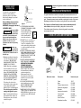
1
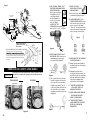
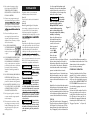
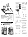
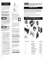
!
CAUTION
Si el motor del guinche se atasca, no continue energizando
el motor.
SERVICIO INTERMITENTE
Un guinche electrico es similar a cualquier otra herramienta electrica, tal
como un taladro o una sierra. No debe permitirse que el motor se sobrecaliente. Tomanado precauciones normales se prolongara la vida util del motor.
Mantenaga la duracion de la traccion con el guinche lo mas corta posible
Si el motor se calienta hasta el punto en que esta demasiado caliente al tacto, interrumpa el trabajo y deje que el moto se enfrie.
Para obtener mas informacion y datos de la garantia, conectese a
www.superwinch.com
!
10.
8.
6.
2.
CAUTION
READ AND UNDERSTAND THIS GUIDE BEFORE
INSTALLATION AND OPERATION.
5.
7.
11.
LT3000 ATV 3,000 lb (1361 kg)
LT4000 ATV 4,000 lb (1814 kg)
12 Volt DC Electric Winch
LT4000 ATV LISTA DE REPUESTOS
1.
OWNER’S GUIDE
Superwinch, LTD.
Union Mine Road
Pitts Cleave
Tavistock, Devon UK
PL19 0NS
tel: +44 (0) 1822 614101
fax: +44 (0) 1822 615204
[email protected]
www.superwinch.com
Superwinch, LLC.
359 Lake Road
Dayville, CT
06241 USA
tel: 1.800.323.2031
fax: 1.860.963.0811
[email protected]
www.superwinch.com
Throughout this manual, you will find notations with the following headings:
Indicates an imminently hazardous situation which, if not avoided,
will result in death or serious injury.
! DANGER
12.
Reference número.
24
9.
Description
4.
3.
Numero de parte
1Cable1511F
2Motor
.87-24078
3
Tambor y barras de unión
87-24075
4Reductor de engranajes87-24079
5Solenoide87-12893
6Interruptor de manubrio87-12894
7Control remoto87-12895
8Interruptor87-22873-16
9Gancho con reten87-42615
10
Dyneema® sintético europa
87-24076
11Guiacabos de rodillos87-12911
12Aluminio Hawse87-24077
!
WARNING
!
CAUTION
Indicates a potentially hazardous situation which, if not avoided,
could result in death or serious injury.
Indicates a potentially hazardous situation which, if not avoided,
may result in minor or moderate injury. This notation is also used
to alert against unsafe practices.
The following symbols on the product and in the Owner's manual are used:
Read Owner's
Manual
Always Use
Handsaver
Keep clear of winch,
wire rope and hook
while operating
Never use winch
to lift or move
people
Never use
winch to hold
loads in place
Note: Indicates additional information in the installation and operation procedures of your winch.
Correct installation of your winch is a requirement for proper operation.
Please Note: Winch is designed primarily for intermittent applications. This winch is not designed to
be used in industrial or hoisting applications and Superwinch does not warrant it to be suitable for
such use.
87-10994 Rev A 4/8/2014
1
GENERAL SAFETY
INFORMATI ON
Your winch is a very powerful
machine. If used unsafely or
improperly, there is a possibility
that property damage or personal
injury could result.
!
SERVICIO INTERMITENTE
Single Line
Note; all Safety references in this
Double Line
manual that refer to the use of,
Figure 2
WIRE ROPE, also apply to the use of,
2. AFTER READING AND UNDERSYNTHETIC ROPE.
STANDING THIS MANUAL, LEARN
The responsibility
TO USE YOUR WINCH.
! WARNING for safe installaAfter installing the winch,
tion and operation of the winch and
practice using it so you
prevention of personal injury and
will be familiar with it
property damage ultimately rests
when the need arises.
with you, the operator. There is no
3. DO NOT“move” your vehicle to
substitute for the use of good
assist the winch in pulling the
judgement and caution in operating
load. The combination of the
a winch.
winch and vehicle pulling together could overload the wire rope
The wire rope
! WARNING
and the winch.
may break before
4. ALWAYS STAND CLEAR OF WIRE
the winch stalls. For heavy loads, use
ROPE, HOOK AND WINCH. IN THE
a pulley block to reduce the load on
UNLIKELY EVENT OF ANY COMthe wire rope.
PONENT FAILURE IT‘S BEST TO BE
1. Maximum working load capacity
OUT OF HARM‘S WAY.
is on the wire rope layer closest
5. INSPECT WIRE ROPE AND EQUIPto the drum. DO NOT OVERMENT FREQUENTLY. A FRAYED
LOAD. DO NOT ATTEMPT PROWIRE ROPE WITH BROKEN
LONGED PULLS AT HEAVY
STRANDS SHOULD BE
LOADS..Overloads can damage
REPLACED IMMEDIATELY.
the winch and/or the wire rope
Always replace wire rope with
and create unsafe operating conthe manufacturer‘s identical
replacement part (see
ditions. FOR LOADS OVER 1,000
Replacement Parts List).
POUNDS (454 kg), WE RECOMPeriodically check the winch
MEND THE USE OF THE OPTIONinstallation to ensure that all
AL PULLEY BLOCK TO DOUBLE
bolts are tight.
LINE THE WIRE ROPE (Figure2).
6.
USE HEAVY LEATHER GLOVES
This reduces the load on the
when handling wire rope. DO
winch and the strain on the wire
NOT LET WIRE ROPE SLIDE
rope by approximately 50%.
THROUGH YOUR HANDS.
Attach hook to load bearing part.
7.
NEVER WINCH WITH LESS THAN 5
The vehicle engine should be
TURNS of wire rope AROUND THE
running during winch operaWINCH DRUM since the wire rope
tion. If considerable winching is
end fastener may NOT withstand
performed with the engine off,
full load.
the battery may be too weak to
restart the engine.
2
Si el motor del guinche se atasca, no continue energizando
el motor.
CAUTION
Un guinche electrico es similar a cualquier otra herramienta electrica, tal
como un taladro o una sierra. No debe permitirse que el motor se sobrecaliente. Tomanado precauciones normales se prolongara la vida util del motor.
Mantenaga la duracion de la traccion con el guinche lo mas corta posible
Si el motor se calienta hasta el punto en que esta demasiado caliente al tacto, interrumpa el trabajo y deje que el moto se enfrie.
Para obtener mas informacion y datos de la garantia, conectese a
www.superwinch.com
LT3000 ATV LISTA DE REPUESTOS
7
1
5
8
10
6
2
9
3
4
Referencia número Descripcion
Numero de parte
1
2
3
4
5
6
7
8
9
10
Cable
Motor
Tambor y barras de unión
Reductor de engranajes
Solenoide
Interruptor de manubrio
Control remoto
Interruptor
Gancho Con Reten
Guiacabos de rodillos
1511F
87-12890
87-12891
87-12892
87-12893
87-12894
87-12895
87-22873-16
87-42615
87-12911
23
Figura 8
Fig ure 6
8. KEEP CLEAR OF WINCH, TAUT
WIRE ROPE AND HOOK WHEN
OPERATING WINCH.
Never put your finger
through the hook. If
your finger should
become trapped in
the hook, you could
lose your finger.
ALWAYS USE THE
HANDSAVER when guiding the
wire rope in or out (See Figure 3 .
CIRCUITO MAESTRO DEL VEHÍCULO
21
Rojocalibre
6
Yellow
6 ga.
GUINCHE
WINCH
CIRCUITO MAESTRO
DEL
ATV M
ASTVEHÍCULO
E R WIRING S
12
Interruptor
AT V main
principal
switch
del vehículo
Blue
6 ga. calibre 6
Negro-
Negro
Green
Fuse
Fusible
Red
Marrón/Azul
Brown/Blue
Negro
Black
BATERÍA
BATT
ERY
Blac kcalibre
6 ga. 6
Negro-
Verde
Azul
Black
Rojo
Red
control
remoto
optiona
lremote
control
ATconexión
V wiring
al circuito
connection
SOLENOIDE
SOLENOID
del vehículo
Green
Negro
optional
CIRCUIT
INTERRUPTOR
BREAKER
" +"
tao solenoide
sol enoi d
Rojo-Red
calibre6 6ga.
se monta
Figur e 7desde
– Socketafuera
hacia
adentro
Assembly
mount s
Ø.86”
Ø 21.8mm
12.Your winch is not intended for
overhead hoisting operations
.
13. AVOID CONTINUOUS PULLS
FROM EXTREME ANGLES a s this
will cause the wire rope to pile
up on one end of the drum
(Figure 6). This can jam the wire
rope in the winch, causing damage to the rope or the winch.
Figure 6
to al
circuit
breaker
interruptor
Figura9 9: El receptáculo
11. NEVER USE YOUR
WINCH FOR LIFTING OR
MOVING PEOPLE.
1.95”
49.5mm
Figure 3
fr om outside/in
MONTAJE DE RECEPTÁCULO DE COMANDO A DISTANCIA
1. Determine la ubicación del receptáculo remoto.
f
.18”
4.6mm
3. Con el receptáculo montado, lleve el cable (con conductores
verde y negro) hasta la solenoide. Conecte el cable rojo a un
conductor que reciba electricidad de la llave de arranque
del vehículo.
.98”
24.8mm
9. NEVER HOOK THE WIRE ROPE
BACK ONTO ITSELF because you
could damage the wire rope.
Use a nylon sling (Figure 4).
embrague cuando el tambor está en movimiento.
Desacoplado
Acoplado
(polea loca)
Figura 10
Desacoplado
Acoplado
(polea loca)
14. NEVER OBSCURE THE WARNING
INSTRUCTION LABELS.
Wrong
Right
Figure 4
10. I t is a good idea to lay a heavy
blanket or jacket over the wire
rope near the hook end when
pulling heavy loads (Figure 5). If
a wire rope failure should occur,
the cloth will act as a damper
and help prevent the rope from
whipping.
16. Equipment such as tackle,
hooks, pulley blocks, straps, etc.
should be sized to the winching
task and should be periodically
inspected for damage that
could reduce their strength.
17..NEVER RELEASE FREESPOOL
CLUTCH WHEN THERE IS A
LOAD ON THE WINCH.
18..NEVER WORK ON OR AROUND
THE WINCH DRUM WHEN
WINCH IS UNDER LOAD.
19.DO
NOT OPERATE WINCH
.
WHEN UNDER THE INFLUENCE
OF DRUGS, ALCOHOL OR
MEDICATION.
20
Figure 5
Figura 10
22
Right
15. A lways operate winch with an
unobstructed view of the winching operation.
EMBRAGUE DE CARRETE LIBRE MANDO
El embrague debeElestar
acoplado
antes
embrague
debe
estarde usar el guinche. Nunca
! PRECAUCIÓN
de colocar laacoplado
perilla del
embrague
el tambor esta en
! PRECAUCION tratar
antes
de usarcuando
el
movimiento.
guinche. Nunca tratar de colocar la perilla del
Wrong
3
20..ALWAYS DISCONNECT WINCH
POWER LEADS TO BATTERY
BEFORE WORKING IN OR
AROUND THE WINCH DRUM so
that the winch cannot be turned
on accidentally.
21. .When moving a load, slowly
take up the wire rope slack until
it becomes taut. Stop, recheck
all winching connections. Be
sure the hook is properly seated.
If a nylon sling is used, check the
attachment to the load.
22 ..When using your winch to move
a load, place the vehicle transmission in neutral, set vehicle
brake, and chock all wheels.
23..DO NOT USE THE WINCH TO
HOLD LOADS IN PLACE.
Use other means of
securing loads such
as tie down straps.
24..USE ONLY FACTORY APPROVED
SWITCHES, REMOTE CONTROLS
AND ACCESSORIES. Use of nonfactory approved components
may cause injury or property
damage and could void your
warranty.
25..DO NOT MACHINE OR WELD
ANY PART OF THE WINCH. Such
alterations may weaken the
structural integrity of the winch
and could void your warranty.
26..DO NOT CONNECT WINCH TO
EITHER 110V AC HOUSE CURRENT OR 220V MAINS AS WINCH
BURNOUT OR FATAL SHOCK
MAY OCCUR.
27. .Never allow shock loads to be
applied to winch or wire rope.
28..Use caution when pulling or
lowering a load up and down a
ramp or incline. Keep people,
pets and property clear of the
path of the load.
4
INSTALLATION
Correct installation of your winch is
required for proper operation.
Step (1)
Disconnect the vehicle battery leads
from the battery.
Step (2)
Secure winch
winchFigure
(Figure)
mounting
Secure
7 totomounting
plate or structural support using the
M8 x 1.25 x 30mm mount bolts, flat
washers, and lock washers provided.
Typical mount is to a flat secure
surface capable of handling the
required loads.
Step (3)
Remove bottom roller from the roller
fairlead. Turn the freespool knob to
disengage and pull a few inches of
wire rope from the drum. Pass the
wire end under the remaining roller,
and then replace the bottom roller.
Next secure the roller fairlead
( Figure 7) to the mounting roller
plate or structural support using the
M8 x 1.25 x 20mm bolts, flat washers,
and lock washers provided.
!
Do not substitute
WARNING any strength grade
weaker than ISO grade 8.8
!
Be sure that both
WARNING the mounting plate
and winch hardware have been properly tightened.
No part of the vehicle
! CAUTION
(skid plates, wiring,
auxiliary lights, tires, ect.) should
impede the operation of your Superwinch®. When mounting, check all
vehicle and winch parts for free operation. Be sure that the winch
mounting location does not significantly
reduce ground clearance.
This winch MUST be
! WARNING
mounted with the
wire rope in the underwind direction.
Improper mounting could damage
your winch and void your warranty.
Utilice los accesorios y ménsulas suministrados para instalar el interruptor de
manubrio. Instale la solenoide cerca de
la batería, en la caja de almacenamiento
bajo el asiento o el chasis.
El interruptor no
debe interferir
con la conducción normal del vehículo.
El cableado NO DEBE estar en
contacto con ninguna parte
Figura 7
como el motor, la suspensión,
los frenos, el escape o la dirección.
! ! ADVERTENCIA
Lleve el cable rojo desde el
interruptor de manubrio
hasta la llave de encendido y conéctelo al
cable que queda
bajo voltaje
cuando se gira
la llave de
contacto a la
posición ON
SOLO.
Lleve los dos cables de la solenoide al
motor (Figura 8) y conéctelos a la batería. Conecte al interruptor al cable rojo.
Envuelva el interruptor con cinta aislante
para evitar cortocircuitos accidentales.
Aplique varias capas de cinta aislante en
los lugares donde los cables puedan entrar
del vehículo.
Conecte el conductor del interruptor al
terminal positivo de la batería y vuelva a
conectar el borne de la batería. El cable
negro de la solenoide debe conectarse al
negativo de la batería antes de volver a
conectar el borne negativo.
Paso (4)
Ponga la perilla del embrague en la posición Desacoplado (tal como se muestra
en la Figura 10). Desenrolle varios pies de
cable del tambor y vuelva a dejar el embrague acoplado. Mueva un momento el
guinche en la dirección de salida de cable
tambor. Si el tambor gira en sentido incorrecto, revise las conexiones eléctricas.
FUNCIONAMIENTO CON POLEA LOCA
Ponga la perilla del embrague en la
posición Desacoplado (tal como se
muestra en la Figura 10). Si hubiera una
carga tirando del cable, la perilla podría
no salir con facilidad. NO FUERCE LA
sión en el cable para aliviar la carga en
el embrague.
Suelte el embrague y tire del cable para
al menos cinco (5) vueltas de cable en el
tambor. Ponga la perilla en la posición de
embrague acoplado (véase la Figura 10).
21
20. Para evitar el arranque accidental del guinche, CUANDO ESTÉ
TRABAJANDO EN EL TAMBOR,
DESCONECTE LOS CABLES DE CONEXIÓN A LA BATERÍA.
21. Al mover una carga mantenga el
cable tirante. Deténgase y revise la
que el gancho esté bien asentado.
Si está usando una eslinga de nylon,
la carga.
22. Al usar el vehículo para mover
una carga, deje la transmisión en
el punto neutral (punto muerto),
aplique el freno de mano y coloque
cuñas en las ruedas.
23. NO USE EL GUINCHE PARA
SOSTENER CARGAS EN
SU LUGAR. Utilice otros
medios, tal como correas
o sogas.
24. USE ÚNICAMENTE INTERRUPTORES,
CONTROLES REMOTOS Y ACCESORIOS APROBADOS POR FÁBRICA. El
uso de componentes no aprobados
por fábrica podría causar accidentes
personales y daños materiales,
además de anular la garantía del
equipo.
25. NO SUELDE NI MAQUINE NINGUNA
PARTE DEL GUINCHE. Estas alteraciones pueden debilitar el guinche
y anular los términos de la garantía.
INSTALACIÓN
El guinche debe ser correctamente
instalado para que funcione bien.
Paso (1)
Desconecte los cables de la batería del
vehículo.
Paso (2)
Monte el guinche Figura 7 en la placa
de montaje o estructura de soporte con
los pernos M8 1.25 x 30 mm, arandelas planas y arandelas de seguridad
suministradas. El montaje típico es sobre
The location
of the switch
MUST not interfere with safe
operation of the vehicle.
Wiring MUST NOT come in
contact with any moving
parts or sharp edges, such
as engine, suspension, brakes,
exhaust, or steering.
soportar la carga.
Paso (3)
Desmonte el rodillo inferior de la guía del
cable, gire la perilla de la polea loca para
desacoplarla y tire algunas pulgadas de
cable del tambor. Pase el extremo del
cable bajo el rodillo guía y vuelva a colocar
Route the Red wire from
the handlebar switch to
the ignition switch and
connect to the wire
that is powered
when ignition
is in the ON
position ONLY.
guía del cable (Figura 7) a la placa de montaje o el soporte estructural con los pernos
M8 x 1.25 x 20 mm, arandelas planas y
arandelas de seguridad suministradas.
No sustituya ningún componente
con otro de resistencia menor a ISO 8.8.
! ADVERTENCIA
! ADVERTENCIA
placa de montaje
y los accesorios del guinche estén
26. NO CONECTE EL GUINCHE A 120 NI
220 VOLTIOS DE CA, YA QUE PODRÍA
QUEMARSE E INCLUSO CAUSAR
UNA ELECTROCUCIÓN LETAL.
N PELIGRO
inguna parte del
!
v
ehículo (patines,
cables, luces auxiliares, neumáticos,
etc.) debe impedir el funcionamiento
normal del Superwinch®. Inspeccione
todas las partes del vehículo y del
27. No deje que el guinche ni el cable
se vean sometidos cargas repentinas de impacto.
que el guinche no reduzca considerablemente la altura libre del vehículo
sobre el suelo.
28. Tome precauciones al tirar o bajar
una carga en una rampa o terreno
inclinado. Mantenga el paso de la
carga despejado de objetos, animales y personas.
E l guinche debe
m ontarse con la
salida y entrada del cable por debajo
del tambor. El montaje incorrecto del
cable dañará el guinche y anulará la
garantía.
20
Use the supplied hardware and
brackets to mount the handlebar
switch. Mount the solenoid close
to the battery, in the storage box,
under the seat or frame.
! ADVERTENCIA
!
WARNING
Figure 7
Route the two
wires from the
solenoid to the motor Figure 8. Route
the two wires from the solenoid to
the battery. Attach the circuit breaker
to the end of the red wire. Wrap the
circuit breaker with electrical tape to
prevent accidental short circuits.
Apply several layers of electrical tape
where wiring may come into contact
with sharp metal parts of the vehicle
to prevent insulation abrasion or cutting.
winch in Cable Out momentarily to
check drum rotation direction. If the
drum rotates in the wrong direction, recheck your wiring.
FREESPOOL OPERATION
Turn the clutch knob to the, Disengaged “Free” position as shown in
Figure 10. If there is a load on the
wire rope, the clutch knob may not
pull out easily. DO NOT FORCE THE
CLUTCH KNOB. Release tension on
Attach the short circuit breaker wire to
the clutch by jogging out some of
the battery positive terminal and reatthe wire rope.
tach the terminal to the battery. ConRelease the clutch and pull out the
nect the remaining black solenoid wire
wire rope and secure to anchor or
to the battery negative terminal and
load. Check that there are at least
connect the terminal to the battery.
five (5) turns of wire rope left on
the drum. Re-engage the drum by
STEP (4)
returning the clutch knob to the,
Turn the clutch knob to, Disengage d
“Engaged”
position. (See Fiqure 10).
“Free” position as shown in Figure 10.
Pull several feet of wire rope off the
drum. Return the clutch knob back to
the, “Engaged” position. Activate the
5
Figure 8
Figure 6
8. MANTÉNGASE ALEJADO DEL CABLE
TENSIONADO Y EL GANCHO. Nunca
ponga los dedos en el
gancho ya que podría
perderlos si le queda la
mano atrapada. USE
SIEMPRE UN GUIADOR
EXTERNO DEL CABLE
(véase Figura 3).
21
Yellow – 6 ga.
Red
WINCH
ATV MASTER WIRINGS
2
1
ATV main
switch
Blue
– 6 ga. 6 ga.
Black-
Black
Green
Fuse
Red
Brown/Blue
Black
Black
BATTERY
Black – 6 ga.
Green
Blue
Black
Red
optional remote
control
ATV wiring
connection
SOLENOID
to solenoid
Green
Black
optional
CIRCUIT
BREAKER
"+"
11. NO USE EL GUINCHE
PARA LEVANTAR NI
MOVER PERSONAS.
12. El guinche no es para levantamiento
vertical de cargas.
13. EVITE LA TRACCIÓN CONTINUA
EN ÁNGULOS MUY ABIERTOS ya
que podría empujar las vueltas de
cable hacia un extremo del tambor
(Figura 6) y se atascará, causando
daño al cable y al guinche.
Red – 6 ga.
to circuit breaker
Figura 6
9
REMOTE SOCKET MOUNTING
Figure 7 – Socket
Assembly mounts
from outside/in
1.95”
49.5mm
Ø.86”
Ø 21.8mm
Figura 3
1. Detemine the mounting location for the remote socket.
2. Drill three holes using the included dimensions as a guide.
3. Once the remote socket is mounted, route the jacketed
green and black leads back to where the solenoid is
mounted. Splice the red lead to a key controlled
electrical wire on the ATV.
.18”
4.6mm
9. NUNCA HAGA UN LAZO CON EL
CABLE ya que podría dañarse. Utilice
una eslinga de nylon (Figura 4).
.98”
24.8mm
FREESPOOL CLUTCH CONTROL KNOB
Clutch must be fully
!
CAUTION
while drum is turning.
Disengaged
(Freespool)
Engaged
Figure 10
Disengaged
Engaged
(Freespool)
Correcto
14. NO OCULTE NI CUBRA LAS ETIQUETAS DE INSTRUCCIONES.
15. Use el guinche con total visibilidad
del área de trabajo.
Incorrecto
CAUTION
Clutch! must
be fully engaged
engagedbefore
beforewinching. Never
engage
clutch Never
knob while
drum
is turning.
winching.
engage
clutch
knob
Incorrecto
Correcto
Figura 4
10. Es aconsejable colgar una lona
pesada sobre el cable, cerca del
gancho, para tirar de cargas pesadas
(Figura 5). Si el cable se cortara, la
lona actuará como amortiguador
para evitar el rebote del cable.
16. Los equipos auxiliares tales como
ganchos, poleas, correas, etc.
ciente para trabajar con el guinche.
Inspeccionarlos periódicamente
encuentran.
17. NUNCA DESACOPLE EL EMBRAGUE
CUANDO HAYA UNA CARGA ACOPLADA AL GUINCHE.
18. NO SE ACERQUE AL TAMBOR DEL
GUINCHE CUANDO LO ESTÁ
USANDO.
6
6
Figure 10
Figura 5
19. NO USE EL GUINCHE CUANDO ESTÉ
BAJO LA INFLUENCIA DE ALCOHOL,
DROGAS O MEDICAMENTOS.
19
INFORMACIÓN GENERAL
DE SEGURIDAD
El guinche es una máquina muy potente
que, si se utiliza de manera insegura o
incorrecta presenta la posibilidad de
causar daños materiales o accidentes
personales.
Tenga en cuenta, todas las referencias en este manual de seguridad que se refieren al uso de,
CABLE DE ALAMBRE, aplica a la
utilización de, cuerda sintética.
Es responsabilidad del usuario
instalar y usar el guinche con seguridad y tomar precauciones para evitar
daños materiales y accidentes personales. No hay reemplazo del sentido
común y la prudencia para usar un
guinche.
! ADVERTENCIA
E l cable podría
romperse incluso
antes de que el guinche se atasque.
Para tirar de cargas pesadas, use un
aparejo de poleas para reducir la
carga en el cable.
! ADVERTENCIA
1. La máxima capacidad de carga está
en la parte del cable enrollada más
cerca del tambor. NO SOBRECARGUE
EL GUINCHE NI INTENTE PROLONGAR LA TRACCIÓN DE CARGAS MUY
PESADAS. La sobrecarga puede
dañar el guinche y/o el cable y crear
condiciones riesgosas de uso. PARA
CARGAS DE MÁS DE 1.000 LIBRAS
(454 Kg) RECOMENDAMOS EL USO
DE UNA POLEA (OPCIONAL) PARA
REDUCIR LA CARGA SOBRE EL CABLE
(Figura 2). Esto reducirá la carga sobre
el guinche y aproximadamente el 50%
de la carga sobre el cable. Acoplar el
gancho a una parte con capacidad de
soportar carga. El motor del vehículo
debe estar en marcha durante el uso
del guinche. Si se usa intensamente
el guinche con el motor detenido, la
batería podría perder mucha carga
para volver a arrancar el vehículo.
18
Línea simple
Línea doble
Figura 2
2. LEA ATENTAMENTE ESTE MANUAL
Y APRENDA A USAR EL GUINCHE.
Después de instalar el guinche,
practique para aprender a
usarlo y estar preparado
cuando llegue la necesidad
de hacerlo.
CAUTION
If the winch motor stalls, do not continue to apply power
If the end of the motor becomes uncomfortably hot to touch, stop
winching and allow the motor to cool down.
!
INTERMITTENT DUTY
An electric winch is like any other motor driven power tool such as an
electric drill or saw. The electric motor should not be allowed to become
excessively hot. Normal precautions will extend the life of your motor.
Keep the durations of pulls as short as possible.
For further information and complete warranty, visit our website
www.superwinch.com
LT3000 ATV REPLACEMENT PARTS LIST
3. NO mueva el vehículo para tratar
de ayudar al guinche. La tracción
conjunta del vehículo y del guinche
podría sobrecargar el cable y también el guinche.
4. M ANTENGASE ALEJADO DEL CABLE,
DEL GANCHO Y DEL GUINCHE. EN
CASO DE FALLA DE ALGÚN COMPONENTE ES MEJOR ESTAR A DISTANCIA.
5. I NSPECCIÓN EL CABLE Y EL EQUIPO
FRECUENTEMENTE. SI EL CABLE
TIENE HEBRAS CORTADAS, DEBE SER
CAMBIADO INMEDIATAMENTE. Use
el cable original del fabricante del
equipo (véase la Lista de repuestos). Inspeccione periódicamente el
pernos estén bien ajustados.
6. Maneje el cable CON GUANTES
GRUESOS DE CUERO. NO DEJE QUE
EL CABLE SE DESLICE EN SUS
MANOS.
7. NO USE EL GUINCHE CON MENOS
DE VUELTAS de cable EN ELTAMBOR,
podría NO soportar la carga total.
7
1
5
8
10
6
2
9
3
4
Reference No.DescriptionPart Number
1Wire Rope Assy.1511F
2
Motor Assy.
87-12890
3Drum and Tie Bars87-12891
4Gearbox Assy.87-12892
5Solenoid Assy.87-12893
6Handlebar Rocker Switch87-12894
7Hand Held Remote87-12895
8Circuit Breaker Assy.87-22873-16
9Clevis Hook Assy.87-42615
10Roller Fairlead87-12911
7
CAUTION
If the winch motor stalls, do not continue to apply power
If the end of the motor becomes uncomfortably hot to touch, stop
winching and allow the motor to cool down.
!
INTERMITTENT DUTY
An electric winch is like any other motor driven power tool such as an
electric drill or saw. The electric motor should not be allowed to become
excessively hot. Normal precautions will extend the life of your motor.
Keep the durations of pulls as short as possible.
For further information and complete warranty, visit our website
www.superwinch.com
! PRECAUCIÓN
5.
7.
10.
8.
11.
6.
2.
LT3000 ATV 3,000 lb (1361 kg)
LT4000 ATV 4,000 lb (1814 kg)
12 Volt DC Cabrestante eléctrico
LT4000 ATV REPLACEMENT PARTS LIST
1.
INSTRUCCIONES DE USO
LEA ATENTAMENTE ESTAS INSTRUCCIONES ANTES
DE INSTALAR Y USAR EL EQUIPO.
Superwinch, LTD.
Union Mine Road
Pitts Cleave
Tavistock, Devon UK
PL19 0NS
tel: +44 (0) 1822 614101
fax: +44 (0) 1822 615204
[email protected]
www.superwinch.com
Superwinch, LLC.
359 Lake Road
Dayville, CT
06241 USA
tel: 1.800.323.2031
fax: 1.860.963.0811
[email protected]
www.superwinch.com
En este manual encontrará notas con los siguientes encabezamientos:
12.
9.
3.
Reference No.DescriptionPart Number
1Wire Rope Assy.1511F
2Motor Assy.87-24078
3
Steel Drum and Tie Bars
87-24075
4Gearbox Assy.87-24079
5Solenoid Assy.87-12893
6Handlebar Rocker Switch87-12894
7Hand Held Remote87-12895
8Circuit Breaker Assy.87-22873-16
9Clevis Hook Assy.87-42615
10
Dyneema® Synthetic Rope
87-24076
11Roller Fairlead87-12911
12Hawse87-24077
8
4.
Indica una situación de peligro inminente que si no se evita podría
causar un accidente grave o incluso la muerte.
Indica una situación potencialmente peligrosa que si no se evita
! ADVERTENCIA podría causar un accidente grave o incluso la muerte.
Indica una situación potencialmente peligrosa que si no se evita
! PRECAUCIÓN podría causar un lesión leve o moderada. Esta nota se utiliza para
advertir sobre el uso de métodos inseguros.
!
PELIGRO
En el producto y en el manual de instrucciones también se utilizan los siguientes símbolos:
Lea las instrucciones de uso
Use siempre un
guiador manual
Manténgase alejado
del guinche, del
cable y del gancho
mientras lo usa
No use el guinche
para levantar ni
mover personas
No use el
guinche para
sostener cargas
en su lugar
Nota: Indica información adicional para la instalación y el uso del guinche.
Para que el guinche funcione normalmente debe instalarse correctamente.
Nota: El guinche está diseñado principalmente para uso intermitente. Este guinche no está diseñado
para aplicaciones industriales o como grúa, y Superwinch no lo garantiza para dichos usos.
17
! ATTENTION Si le moteur du treuil cale, cessez son utilisation.
Si l extremite du moteur devient difficlea toucher, arretez le treuillage et laissez le moteur se refroidir.
SERVICE INTERMITTENT
Un treuil electrique se comporte comme un autre outil tel qu une scie ou
une perceuse electrique. Le moteur electrique ne doit pas devenir trop
chaud. De precautions normales etendront la duree de vie de votre
moteur. La duree des tractions doit etre aussi courte que possible.
Pour de plus amples informations et une garantie complete, rendez-vous
sur www.superwinch.com
LT4000 ATV LISTE DE PIECES DE RECHANGE
1.
LT3000 ATV 3,000 lb (1361 kg)
LT4000 ATV 4,000 lb (1814 kg)
12 Volt DC treuil électrique
! ATTENTION
5.
7.
10.
8.
11.
MANUEL DU PROPRIÉTAIRE
6.
2.
VEUILLEZ LIRE ET COMPRENDRE CE GUIDE AVANT
TOUTE UTILISATION OU FONCTIONNEMENT
Superwinch, LTD.
Union Mine Road
Pitts Cleave
Tavistock, Devon UK
PL19 0NS
tel: +44 (0) 1822 614101
fax: +44 (0) 1822 615204
[email protected]
www.superwinch.com
Superwinch, LLC.
359 Lake Road
Dayville, CT
06241 USA
tel: 1.800.323.2031
fax: 1.860.963.0811
[email protected]
www.superwinch.com
Tout au long de ce manuel, vous trouverez des annotations avec les en-têtes suivants :
Indique un danger imminent qui, s’il est ignoré, peut provoquer des
blessures graves, voire mortelles.
Indique une situation potentiellement dangereuse qui, si elle est
! AVERTISSEMENT
ignorée, peut provoquer des blessures graves, voire mo
rtelles.
Signale une situation dangereuse éventuelle qui, si elle est ignorée,
! ATTENTION
peut causer des blessures légères. Cette notation est aussi utilisée
pour vous alerter contre des pratiques dangereuses.
!
12.
Reference
9.
4.
3.
numéroter
DescriptionNo
Piece
1Cable 1511F
2Moteur87-24078
3Tambour et tirants87-24075
4Boite de vitesses87-24079
5Solenoide87-12893
6Contacteur bascule guidon87-12894
7Telecommande87-12895
8Disjoncteur87-22873-16
9Crochet a chape87-42615
10
Dyneema® synthétique corde
87-24076
11rouleau Chaumard87-12911
12Hawse87-24077
16
DANGER
Les symboles suivants sur le produit et dans le manuel du propriétaire sont utilisés :
Lisez le Manuel
du Propriétaire
Utilisez toujours
un système de
protection des
mains
Tenez-vous à l’écart
du treuil, du câble et
du crochet pendant
le fonctionnement
N’utilisez jamais
le treuil pour
soulever ou déplacer
une personne
N’utilisez jamais
le treuil pour
maintenir des
charges en place
Remarque : Indique des informations complémentaires sur l’installation et sur les procédures de
fonctionnement de votre treuil.
L’installation correcte de votre treuil est impérative pour un bon fonctionnement.
Veuillez noter : Le treuil est principalement conçu pour des applications intermittentes. Ce treuil
n’est pas conçu pour être utilisé dans des applications industrielles ou de levage, et Superwinch ne
le garantit pas comme étant adapté à une telle utilisation.
9
! ATTENTION Si le moteur du treuil cale, cessez son utilisation.
Si l extremite du moteur devient difficlea toucher, arretez le treuillage et laissez le moteur se refroidir.
INFORMATIONS GÉNÉRALES
DE SÉCURITÉ
Votre treuil est une machine très puissante. S’il n’est pas correctement utilisé en
sécurité, des dommages matériels ou un
accident peuvent se produire.
Remarque, toutes les références dans ce manuel
de sécurité qui se réfèrent
à l'utilisation de, CÂBLE,
s'applique également à
l'utilisation d'un câble
synthétique.
L a responsa-
! AVERTISSEMENT bilité d’une
installation et d’un fonctionnement
Câble double
Figure 2
2. APRÈS AVOIR LU ET COMPRIS CE
MANUEL, APPRENEZ À UTILISER VOTRE
TREUIL. Après avoir installé
le treuil, exercez-vous sur
3. NE DÉPLACEZ PAS votre véhicule pour
aider le treuil à tracter une charge. La
traction du winch ajoutée à celle du
véhicule peuvent surcharger le câble
et le treuil.
L e câble peut
! AVERTISSEMENT
s e rompre avant
que le treuil ne cale. Avec de lourdes
4. TENEZ-VOUS TOUJOURS À L’ÉCART DU
CÂBLE, DU CROCHET ET DU TREUIL.
DANS LE CAS PEU PROBABLE DE LA
PANNE D’UN COMPOSANT, IL EST TOUJOURS PRÉFÉRABLE D’ÊTRE EN DEHORS
DE LA ZONE DANGEREUSE.
1. La charge maximum de travail se
trouve sur l’enroulement de câble le
plus proche du tambour. NE SURCHARGEZ PAS LE TREUIL. N’EFFECTUEZ
PAS DE LONGUES TRACTIONS SUR DES
CHARGES ÉLEVÉES. Les surcharges
peuvent endommager le treuil et/ou le
câble, et créer des conditions de fonctionnement dangereuses. POUR DES
CHARGES SUPÉRIEURES À 1000 LIVRES
(454 kg), NOUS RECOMMANDONS
L’UTILISATION D’UN PALAN OPTIONNEL POUR DOUBLER LE CÂBLE (FIGURE
2). Ceci réduit la charge sur le treuil et
la contrainte sur le câble d’environ 50
%. Fixez le crochet à la partie portant
la charge. Le moteur du véhicule doit
être en fonctionnement pendant le
treuillage. Si un grand nombre de
treuillages est réalisé avec le moteur à
l’arrêt, la batterie peut être trop faible
pour redémarrer le moteur.
10
Un treuil electrique se comporte comme un autre outil tel qu une scie ou
une perceuse electrique. Le moteur electrique ne doit pas devenir trop
chaud. De precautions normales etendront la duree de vie de votre
moteur. La duree des tractions doit etre aussi courte que possible.
Pour de plus amples informations et une garantie complete, rendez-vous
sur www.superwinch.com
LT3000 ATV LISTE DE PIECES DE RECHANGE
familiariser à son utilisation lorsque le besoin se
présentera.
accident et des dommages matériels
vous incombent en dernier lieu, à vous,
l’opérateur. Rien ne vaut l’utilisation du
bon sens et d’être précautionneux en
faisant fonctionner un treuil.
la charge sur le câble.
SERVICE INTERMITTENT
Câble unique
5. INSPECTEZ FRÉQUEMMENT LE CÂBLE
ET L’ÉQUIPEMENT. UN CÂBLE EFFILOCHÉ AVEC DES TORONS BRISÉS DOIT
ÊTRE IMMÉDIATEMENT REMPLACÉ.
Vous devez toujours le remplacer par
un câble de remplacement identique
du fabricant (reportez-vous à la liste
de vous assurer que tous les boulons
sont serrés.
6. UTILISEZ DES GANTS ÉPAIS EN CUIR en
manipulant le câble. NE LAISSEZ PAS LE
CÂBLE FILER ENTRE VOS MAINS.
7. LE TREUILLAGE DOIT TOUJOURS
S’EFFECTUER AVEC 5 TOURS DU CÂBLE
AUTOUR DU TAMBOUR dans la mesure
où le système de serrage de l’extrémité
du câble peut ne pas supporter une
pleine charge.
7
1
5
8
10
6
2
9
3
4
Reference numéroter
DescriptionNo Piece
1Cable 1511F
2Moteur87-12890
3Tambour et tirants87-12891
4Boite de vitesses87-12892
5Solenoide87-12893
6Contacteur bascule guidon87-12894
7Telecommande87-12895
8Disjoncteur87-22873-16
9Crochet a chape87-42615
10Rouleau Chaumard87-12911
15
Figure 8
Figu re 6
8. É LOIGNEZ-VOUS DU TREUIL, DU CÂBLE
SOUS TENSION ET DU CROCHET EN
FAISANT FONCTIONNER LE TREUIL.
Ne mettez jamais vos
doigts dans le crochet.
Si un de vos doigts était
pris dans le crochet, vous
pourriez le perdre. UTILISEZ
TOUJOURS LE SYSTÈME
DE PROTECTION DES MAINS
lorsque vous guidez le câble
pour le sortir ou l’enrouler
CIRCUITO MAESTRO DEL VEHÍCULO
21
RougeYellow 6–ga.
6 ga.
TREUIL
WINCH
CÂBLAGE
ATV
ATV PRINCIPAL
MASTE R WIRINGS
12
Contacteur
ATV main
ATV
switch
principal
Blue
– 6 ga.
6 ga.
Noir-
Noir
Black
Noir
Green
Fuse
Fuse
Rouge
Red
Brun/Bleu
Brown/Blue
BATTERIE
BATTE
RY
Black
ga.
Noir-–66ga.
Vert
Bleu
Black
Rouge
Red
Télécommande
optional
remote
control
Connexion
ATV
wiring
câblage ATV
connection
SOLÉNOÏDE
SOLENOID
Green
Noir
optional
9
Le support
se monte
l’extérieur
Figur e 7de
– Socket
versAssembly
l’intérieur
mount s
Ø.86”
Ø 21.8mm
Figure 6
Figure 3
fr om outside/in
1. Déterminez l’emplacement de montage de la douille de
la commande à distance.
2. Percez trois trous en utilisant les dimensions incluses à titre
de guide.
3. Une fois que le commutateur est monté, faites cheminer
les câbles isolés vert et noir vers l’emplacement de
montage du solénoïde. Épissez le câble rouge
sur le câble de clé de contact électrique sur le VTT.
.18”
4.6mm
9. NE POSEZ JAMAIS LE CROCHET SUR LE
CÂBLE LUI-MÊME, SINON VOUS POURRIEZ L’ENDOMMAGER. Utilisez une
.98”
24.8mm
L’embrayage
êtreun treuillage. Ne jamais
Lembrayage
doit être
embrayedoit
avant
! ATTENTION
embrayé avantquand
un treuillage.
ATTENTION tourner le bouton d’embrayage
le tambour est en
Ne jamais tourner le bouton d’embrayage
rotation.
quand le tambour est en rotation.
Debraye
Embraye
Figure 10
Débrayé
Embrayé
(crabot)
Incorrect
Figure 4
Figure 10
Correct
10. C’est une très bonne idée que de
recouvrir le câble avec une couverture
ou une veste à proximité du crochet
5). En cas de rupture du câble, le vêtement agira comme un amortisseur et
empêchera au câble de se comporter
comme un fouet.
Figure 5
13
Incorrect
Correct
14. LES ÉTIQUETTES D’INSTRUCTION
ET D’AVERTISSEMENT DOIVENT
TOUJOURS ÊTRE VISIBLES.
15. Faites fonctionner le treuil en ayant toujours la visibilité totale de
l’ensemble des opérations de
treuillage.
Gratuit
bobine d’embrayage
bouton de
commande
FREESPOOL
CLUTCH CONTROL
KNOB
14
-
1.95”
49.5mm
MONTAGE DE LA PRISE DE TÉLÉCOMMANDE
(crabot)
13. ÉVITEZ DES TRACTIONS DE LONGUE
DURÉE SOUS DES ANGLES EXTRÊMES, ce qui pourrait provoquer
l’accumulation du câble sur un seul
Red 6– ga.
6 ga.
RougetoVers
circuit
breaker
disjoncteur
!
12. Votre treuil n’est pas destiné à fonctionner comme un palan
rait coincer le câble sur le treuil et
endommager l’un ou l’autre.
CIRCUIT
DISJONCTEUR
BREAKER
"+"
to solénoïde
solenoid
Vers
11. N ’UTILISEZ JAMAIS VOTRE
TREUIL POUR SOULEVER
OU DÉPLACER DES
PERSONNES.
16. Des équipements tels qu’un tirefort,
crochet, palan, sangle, etc. doivent
être convenablement dimensionnés pour la tâche et doivent être
régulièrement inspectés à la recherche de détériorations pouvant réduire
leur résistance.
17. N E DÉCRABOTEZ JAMAIS LORSQUE
LE TREUIL EST EN CHARGE.
18. N E TRAVAILLEZ NI N’ÉVOLUEZ JAMAIS
À PROXIMITÉ DU TAMBOUR DU TREUIL
PENDANT QUE CE DERNIER EST EN
CHARGE.
19. IL EST INTERDIT DE FAIRE FONCTIONNER LE TREUIL SOUS L’EMPRISE DE
L’ALCOOL, DE DROGUES OU DE
MÉDICAMENTS.
11
20. V OUS DEVEZTOUJOURS DÉCONNECTER
LES CÂBLES D’ALIMENTATION ENTRE
LE TREUIL ET LA BATTERIE AVANT DE
TRAVAILLER OU D’ÉVOLUER AUTOUR
que le treuil ne soit mis sous tension
par inadvertance.
21. L orsque vous déplacez une charge,
mettez lentement sous tension le
câble jusqu’à obtention de son raidistoutes les connexions de treuillage.
Assurez-vous que le crochet se
trouve correctement en place. En cas
d’utilisation d’une élingue en nylon,
22. L orsque vous utilisez votre treuil
pour déplacer une charge, la boîte de
vitesse doit se trouver au point mort,
le frein à main serré et toutes les roues
bloquées.
23. N ’UTILISEZ PAS LE TREUIL POUR
MAINTENIR DES CHARGES
EN PLACE. Utilisez un autre
moyen de maintenir une
charge comme des sangles
d’arrimage.
24. UTILISEZ SEULEMENT DES CONTACTEURS, DES COMMANDES À DISTANCE
ET DES ACCESSOIRES APPROUVÉS
USINE. L’utilisation de composants
non approuvés usine peut provoquer
des blessures ou des dégâts matériels,
et annuler la garantie.
25. VOUS NE DEVEZ NI SOUDER, NI
USINER AUCUNE PIÈCE DU TREUIL.
réduire l’intégrité structurelle du
treuil et annuler la garantie
26. N E CONNECTEZ JAMAIS LE TREUIL
À DU SECTEUR 110 OU 220 V DE LA
MAISON, CE QUI AURAIT POUR EFFET DE DÉTRUIRE LE TREUIL OU DE
PROVOQUER UNE ÉLECTROCUTION.
27. Ne permettez jamais qu’une charge
de rupture soit appliquée au treuil ou
au câble.
28. Soyez précautionneux en tractant
ou en abaissant une charge sur une
rampe ou un plan incliné. Éloignez les
personnes, les animaux domestiques
et les biens hors du passage de la
charge.
12
INSTALLATION
L’installation correcte de votre treuil est
impérative pour un bon fonctionnement.
Étape (1)
Déconnectez les câbles sur la batterie du
véhicule.
Étape (2)
Utilisez le matériel et les supports fournis
pour monter le contacteur sur le guidon.
Montez le solénoïde à proximité de la batterie dans le boîtier de rangement, sous le
siège ou sur le châssis.
Fixes le treuil figure 7 sur la plaque de
L’emplacement
du contacteur NE
DOIT PAS interférer avec le bon fonctionnement du véhicule. Le câblage NE DOIT
PAS entrer en contact avec des pièces
en mouvement ou des éléments
tranchants, comme le moteur,
Figure 7
la suspension, les freins,
l’échappement ou la direction.
capable de supporter les charges requises.
Étape (3)
Démontez le rouleau inférieur du guidecâble à rouleaux. Faites tourner le bouton du
décrabotage pour désembrayer le tambour
et tirer quelques pouces de câble. Faites
passer l’extrémité du câble sous le rouleau
restant et remettez en place le rouleau in-
Faites cheminer le câble rouge entre
le contacteur sur le guidon et le
contacteur d’allumage, et
connectez le câble
alimenté SEULEMENT lorsque
l’allumage
est sur la
position ON
SEULEMENT.
montage ou sur un support structurel en
utilisant les boulons de montage M8 x
1.25 x 30 mm, les rondelles plates et les
rondelles de blocage fournis. Le montage
sur la plaque de montage ou sur un support
structurel en utilisant les boulons de montage M8 x 1.25 x 20 mm, les rondelles plates
et les rondelles de blocage fournis.
N e substituez
aucun matériel
par un article de résistance ISO inférieure
à 8,8.
! AVERTISSEMENT
Assurez-vous
! AVERTISSEMENT
que la plaque
treuil ont été correctement serrés.
Aucune pièce du
véhicule (plaque de
protection, câblage, éclairage auxiliaire, pneus, etc.) ne doit entraver le bon
fonctionnement
de v otre Superwinch®.
!
DANGER
fonctionnement de l’ensemble du véhicule et des pièces du treuil. Assurez-vous
que l’emplacement de montage du treuil
garde au sol.
Ce treuil DOIT
ê tre monté avec
le câble dans la direction du déroulement.
Un montage incorrect peut endommager
le treuil et annuler la garantie.
! AVERTISSEMENT
!
! AVERTISSEMENT
Faites cheminer
les deux câbles
depuis le solénoïde jusqu’au moteur,
Figure 8. Faites cheminer les deux câbles
depuis le solénoïde jusqu’à la batterie.
Fixez le disjoncteur sur l’extrémité du câble
rouge. Entourez le disjoncteur avec du
courts-circuits accidentels.
Appliquez plusieurs couches de ruban
adhésif sur les emplacements où le câblage
peut entrer en contact avec des parties
d’éviter l’abrasion ou l’entaillage de l’isolant.
Fixez le câble du disjoncteur sur la prise
positive et connectez-la sur la borne positive de la batterie. Connectez le câble noir
restant du solénoïde sur la prise négative
et connectez-la sur la borne négative de la
batterie.
Étape (4)
Tournez le bouton d’embrayage sur la
position « Libre » de débrayage selon la
pieds de câble hors du tambour. Remettez
le bouton d’embrayage sur la position
« Embrayée ». Activez momentanément le
treuil sur la position Cable Out (sortie du
du treuil. Si le tambour tourne dans la
votre câblage.
FONCTIONNEMENT EN DÉCRABOTAGE
Tournez le bouton d’embrayage sur la
position « Libre » de débrayage selon la
en charge, le bouton d’embrayage peut
LE BOUTON D’EMBRAYAGE. Libérez la tension sur l’embrayage en faisant avancer et
reculer le câble.
Libérez l’embrayage, tirez sur le câble
(5)
au minimum sont enroulés autour du
tambour. Embrayez à nouveau le tambour
en positionnant le bouton d’embrayage sur
« Engaged » (embrayé). (Reportez-vous à la
(
13