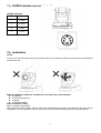
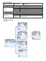
1
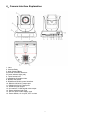
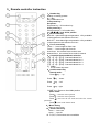
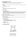
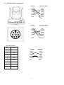
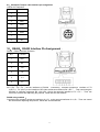
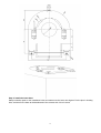
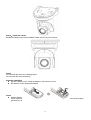
Minrray UV83 Video Conference Camera User Manual www.Minrray.com (800) 486-5276 Forward Thank you very much for buying our cameras, please contact us if there is any doubts anytime. This manual may have technical error, product functions may not conform to actual operation or may have wrong printings. The content of this manual will be updated as product functions strengthened. Please note the updated content will be added in the new version manual without notice. WARNING! This product can be only used in specified range in order to avoid any damage or danger. It must not be installed where exposed to rain and moisture Do not open the camera box as to prevent the danger of electric shock;; Installation and servicing should only be done by qualified service personnel;; It must not be installed where exposed to rain and moisture and it can not be used in unqualified temperature, humidity and power supply. Only use replacement parts recommended by manufacturer. Please use the soft cloth to clean the dome. Use neuter cleanser if bad smeared. No use the strong or corrosive cleanser avoiding scuffing. Be cautious of moving, never press the drive parts heavily avoiding dome troubles. Caution ! The image may be effected in Electromagnetic field under characteristic frequency. 1 【Contents】 1、NOTE............................................................................................................................................................................3 2、MAIN FEATURES: ...................................................................................................................................................... 4 3、SUPPLIED ACCESSORIES .......................................................................................................................................4 4、CAMERA INTERFACE EXPLANATION.................................................................................................................... 5 8、CONNECTION ............................................................................................................................................................. 9 9、CAMERA INTERFACE EXPLANATION : .................................................................................................................9 10、RS485,RS422 INTERFACE PIN ASSIGNMENT . ........................................................................................... 11 11、SVIDEO INTERFACE PIN ASSIGNMENT .......................................................................................................... 12 12、INSTALLATION ..................................................................................................................................................... 12 13、OPERATION .......................................................................................................................................................... 15 14、MENU CONTROL.................................................................................................................................................. 19 15、MAINTENANCE AND TROUBLESHOOTING.................................................................................................... 24 16、SPECIFICATION ................................................................................................................................................... 24 17、DIMENSION........................................................................................................................................................... 26 2 1、Note Electrical Safety The installation of this product must be completely according to the national or regional electric specification. Careful Transportation To prevent the product from the damage of stress, violent vibration and marination when under transportation, storage and installation. Polarity The power supply of the product is 12VDC, the max electrical current is 2A. Polarity of the power supply is as following drawing Careful Installation Never move the camera by seizing the camera head. Don’t rotate camera head by hand, otherwise, mechanical trouble will occur. 1.This series item must put on the smooth desk or platform, and it can not be installed slantways;; 2.If the camera is installed on TV or computer, the base can be fixed by three double-sided adhesive tray. 3.Don’t apply in corrosive liquid, gas or solid environment to aovid the cover which is made up of organic material, 4.To make sure no obstacle in rotation range. 5.Never power on before installation is not completed. Don’t dispatch discretionarily This product has no spare parts for self repair, we will not guarantee the damage caused by self disassembly. 3 2、Main Features: Standard Definition Video 1/4 inch high quality EXVIEW HAD CCD sensor。 18x optical zoom F1.4--3.0 Fast, accurate and stable auto focus lens, 18 x optical zoom;; F1.4~3.0, mechanical shutter。 Wide range, high speed and low noise pan/tilt rotation Step motor driving, smooth rotation and user friendly without dithering. Moving to the appointed position quickly and accurately, meanwhile, shooting large area. Multiple video output format Support AV interface CVBS video signal and S interface SVIDEO video output RS-232C remote controller (VISCA protocol) RS-232C (VISCA protocol) interface: All setting of camera and pan/tilt/zoom can be remote high speed communication controlled. RS-485/RS-422 remote control(P/D/VISCA protocol) RS-485/RS-422 (P/D /VISCA protocol) interface (3.81mm): All setting of camera and pan/tilt/zoom can be remote high speed communication controlled. 256 presets User can preset the pan/tilt/zoom for 256 presets(P/D protocol: 256 presets;;VISCA protocol: 16) and reserve the preset data when power off. Support camera Inversion Support camera inversion, user can set the pan/tilt/zoom, vertical flip, image inversion command and with power off self restoring function Multi-function remote controller Equipped with easy and convenient remote controller;; Except the basic setting and the control of Pan,Tilt,zoom, it can also set the relative parameters of camera by the remote controller.. English OSD menu User can set the camera parameters and rotation parameters by OSD menu. 3、Supplied Accessories When you unpack, check that all the supplied accessories are included: Camera……………………………...1 AC power adapter…………………..1 Remote controller…………………...1 RS232 communication cable……….1 VISCA OUT cable(Optional) ……….1 S-VIDEO cable…………………. …..1 Double-sided pads………………….4 User manual…………………………1 Certificate…………………………….1 4 4、Camera Interface Explanation 1. Lens 2. Camera Body 3. Main Camera Base 4.Remote Controller Receiver 5.Power indicator light (red) 6. Tripod screw hole 7.Installation Orientation Hole 8. Bottom dial Switch 9. RS485 and RS422 control interface 10. RS232 VISCA OUT output port 11. RS232 VISCA OUT input port 12. SVIDEO signal output 13. AV interface, CVBS signal video output 14. Power indicator light (red) 15. DC12V Input Power Supply Jack 16. Power Switch, On is open, OFF is close 5 5、Remote controller instruction 1、Number key Setting or locating presets 2、* key Key combination use 3.Set preset key: Set preset: Set preset key + 0-9 number key: Clear preset key: Clear preset key + 0-9 number key or:#+#+#:clear all the presets 4、BLC control key BLC ON:open black light compensation(Only available in the exposure mode effective for Auto) BLC OFF:close black light compensation(Only available in the exposure mode effective for Auto) 5、Focus control key Focus+:focus length far from near Focus-:focus length near from far Auto focus:the camera focus mode is auto Manual focus:the camera focus mode is manual 6、Controlled Camera address selection 【*】+【#】+【F1】:Camera Address No.1 【*】+【#】+【F2】:Camera Address No. 2 【*】+【#】+【F3】:Camera Address No. 3 【*】+【#】+【F4】:Camera Address No. 4 7、 # key #+#+# delete all presets 8、pan/tilt control key Normal mode: Press key :up Press key :down Press key :left Press key:right “HOME” key: Return to the middle position Menu mode: Press :select the menu upwards Press :select the menu upwards Press :enter into the sub menu and select the current parameter Press :back to the former menu 9、Menu setting Open or close menu 10、Zoom Control key zoom+:lens near zoom-:lens far 11. F1,F2,F3,F4 functions are unavailable. 6 6、Camera Basic Function 18X optical zoom With 18x optical zoom lens and wide angle lens, absolutely meet all sizes meeting room ‘s needs. Can be controlled by IR remote controller and VISCA command by RS232 interface. Focus Auto focus mode and manual focus mode. Can be controlled by IR remote controller and VISCA command. 1, Auto Focus 2, Manual Focus(put on reserve) Iris 1, Auto iris mode 2, Manual iris mode(Control by serial interface command) Electric Shutter Auto electric shutter Black light compensation The object will become dark like shadow when the background turn up the highlight. The BLC function is the lens can compensate the brightness of darker objects and adjust the brighter background when under highlight, this is can help to prevent the image become too bright because of too highlight of the background and the object will not be recognizable, so the camera can capture the clear image. Multiple white balance functions According to the different applications, multiple white balance modes can be set to adjust the various light environment and ensure the operator a vivifying image. Video freeze function Open the video freeze function, the extra video during running the preset will not be displayed, this can reach the effect of image switch. Multi-control modes 1、 by IR remote controller 2、 by RS-232 serial interface, P/D protocol. VISCA protocol 3、 by RS-485 serial interface, P/D protocol 4、 by RS-422 serial interface, P/D protocol. VISCA protocol Multi-SD video output 1、 CVBS 2、 SVIDEO video signal output 7、Dial Switch Setting 7 Note: SW1 dial switch position 4、5、6、7、8 are corresponding to the setting of Baud rate , IR remoter (on/off) and software update model /normal working mode switching . Note:VISCA Protocol only working with 9600 Baud rate . SW1 SWITCH SETTING Baud rate , IR remoter and interface update setting SW1-7 SW1-8 SW1-4 SW1-5 SW1-6 77 Desktop Mount ON -- -- -- -- In ceiling Mount OFF -- -- 1200 2400 -- -- OFF ON OFF OFF -- -- -- -- 4800 -- OFF ON -- -- 9600 -- ON ON -- -- IR Remoter IR Remoter Normal Working mode Software update mode -- -- -- -- -- -- OFF ON -- -- -- -- -- -- -- -- -- -- ON OFF Note: SW1 dial switch position1、2、3 are to be set the receiving address . P control Protocol address setting SW1 Switch Setting Address SW1-1 SW1-2 SW1-3 1 OFF OFF OFF 2 ON OFF OFF 3 OFF ON OFF 4 ON ON OFF 5 OFF OFF ON 6 ON OFF ON 7 OFF ON ON 8 ON ON ON D Control Protocol address setting : VISCA Control Protocol address setting : Switch Setting Switch Setting Address Address SW1-1 SW1-2 SW1-3 SW1-1 SW1-2 SW1-3 1 ON OFF OFF 1 ON OFF OFF 2 OFF ON OFF 2 OFF ON OFF 3 ON ON OFF 3 ON ON OFF 4 OFF OFF ON 4 OFF OFF ON 5 ON OFF ON 5 ON OFF ON 6 OFF ON ON 6 OFF ON ON 7 ON ON ON 7 ON ON ON 8 8、Connection 9、Camera Interface explanation : Control Interface RS-232 RS232 series interface , wiring is standard VISCA cable , one of the linker is 8pin mini DIN(1), the other is RS232C 9 core square linker (DB-9),which connect with computer or conference TV terminal . Standard definition video signal CVBS AV interface, SD compound video signal Standard definition video signal SVIDEO SVIDEO SD video signal VISCA out connecting cable (not attached ) Communication cable to connect the interfaces of two cameras Power supply interface DC 12V Input power supply is adopted external adapter to offer 12V/2A DC . BNC polarity of power supply is shown as following external adapter : Power supply switch ON is open, OFF is close Power Indicator Light(Red) Power supply Switch is “ON”: indicator light is open , otherwise , indicator light is close ,no power or voltage is abnormal 9 9.1、VISCA RS-232 pin assignment Camera Windows DB-9 1.DTR 1.CD 2.DSR 2.RXD 3.TXD 3.TXD 4.GND 4.DTR 5.RXD 5.GND 6.GND 6.DSR 7. 7.RTS 8.NC 8.CTS 9.RI Camera Windows DB-25 1.DTR 1.FG 2.DSR 2.TXD 3.TXD 3.RXD 4.GND 4.RTS 5.RXD 5.CTS 6.GND 6.DSR 7. 7.GND 8.NC 20.DTR VISCA IN Definition No. Function Camera Mini DIN 1 DTR 1.DTR 1.DTR 2 DSR 2.DSR 2.DSR 3.TXD 3.TXD 3 TXD 4.GND 4.GND 5.RXD 5.RXD 4 GND 6.GND 6.GND 7. 7.NC 5 RXD 8.NC 8.NC 6 GND 7 8 NC 10 9.2、VISCA OUT output cable interface pin assignment VISCA OUT Definition: NO. Function 1 2 3 RXD 4 GND 5 TXD 6 GND 7 8 NC 10、RS485,RS422 Interface Pin Assignment . RS485、RS422 Interface Definition : NO. Function 1 RX + 2 RX - 3 TX + 4 TX - 5 A + 6 B - RS422 using method : RX +,RX -,TX +,TX – are the interfaces of RS422 . Connecting controller equipment interface of TX +(OUT+),TX –(OUT-) to the interface of SD video conference camera’s RX +,RX – . Then connecting the interface of controller equipment RX +(IN+),RX –(IN-)to the camera’s interface of TX +,TX – . Then can control the camera after adjusting the protocol , Baud rate and the Address . RS485 using method : Connecting the controller equipment interfaces of A, B to the camera interfaces of A +,B - . Then can control the camera after adjusting the protocol , Baud rate and the Address . 11 11、SVIDEO interface pin assignment SVIDEO Definition: No. Function 1 Y-GND 2 C-GND 3 Y-OUT 4 C-OUT 12、Installation Notice: Do not move the camera by seizing the camera head;; do not rotate the camera turn by force lest mechanical malfunction occur. Multiple installation modes are available for users upon the on-site situation on desktop on terminal equipment on tripod on hoisting bracket Steps to install in ceiling Step 1: install the upper base Drill three holes on the ceiling, with the size (4mm in diameter) and position corresponds to the slots on the ceiling base. Put M4 expansion screw in each hole and fix the base on ceiling with screw cap and spacer. 12 Step 2: install the lower base Stamp insulation pads on the installation holes and make sure the holes are aligned. Put the pins in locating hole, and then fix the base at the baseboard of the camera with 1/4 inch screw. 13 Step 3:Install the camera Buckle the clasps to the fixed installation board and fix it by 3 M3 screws. Notice Do not install the camera on shaking object Do not install the camera obliquely Batteries installation Open the battery cover, install the batteries, and close the cover. Be attention to the anode and cathode Notice Change batteries if the remoter does not work properly When control the camera, make the remoter point directly to the camera;; Remoter cannot work properly when there is obstruction between them. 14 13、Operation Boot-strap 1、 Check if the wire connection is right before powering on. 2、 Turn on the switch at the back of camera and the indicator light on ( RED) 3、 Camera initialization begins as soon as powering on. It turn to the right limit position, down limit and the left limit in sequence, and then run to the right middle position and stop there, that means the initialization is complete. 4、 “CONFIGURE OK” on the menu means the camera is ready . IR remote control When the camera is working, users can control the pan/tilt/zoom, setting and taking preset positions via remote controller Instruction: 1、 In this instruction, “press the key” means a click other than a long-press, and a special note will be given if a long-press for more than one second is required. 2、 When a key-combination is required, do it in sequence. For example, “+#+F1”means press“*”first and then press“#” and press“F1”at last. 1. Camera Remote Controller Address Setting 【*】+【#】+【F1】:Camera Address No.1 【*】+【#】+【F2】:Camera Address No. 2 【*】+【#】+【F3】:Camera Address No. 3 【*】+【#】+【F4】:Camera Address No. 4 2. Pan/Tilt Control Up: press Down: press Left: press Right: press Back to middle position:press“HOME” Press and hold the up/down/left/right key, the pan/tilt will keep running, from slow to fast, until it run to the endpoint;; The pan/tilt running stops as soon as the key is released. 15 3. Zoom Operation ZOOM OUT: press “ZOOM -“ key ZOOM IN: press “ZOOM +” key Press and hold the key, the camera will keep zooming in or zooming out and stops as soon as the key is released. 4.,Focus Control Focus (far): Press ”focus+” key Focus (near): Press “focus-“key Auto Focus: Press "auto" Manual Focus: Press "manual" Press and hold the key, the action of focus continues and stops as soon as the key is released. 5、BLC Setting BLC ON: Open BLC BLC OFF:Close BLC 6、Presets setting To set a preset position, the users should press the “SET PRESET” key first and then press the number key 0-9 to set a relative preset, 10 preset positions in total are available. 7、Preset Clearing To clear a preset position, the user can press the “CLEAR PRESET” key first and then press the number key 0-9 to clear the relative preset;; Or press the“#” key three times to cancel all the presets. 16 8、Run Presets Press a number key 0-9 directly run to a set preset. It will be invalidated if with no preset set. 9. Menu setting Press MENU key to open or close menu Menu mode: Press :select the menu upwards Press :select the menu upwards Press :enter into the sub menu and select the current parameter Press :back to the former menu COM Control In default working mode, the camera is able to communicate with video conferencing terminal via RS-232C command. The baud rate of RS232 COM is 9600 bit/s, and each frame date includes 1 start bit, 8 data bits and 1 stop bit. Connected to power, the camera runs to the right middle position, with the lowest zoom rate, auto focusing and default iris data. The users can control the pan/tilt/zoom, manual focus, presets setting and running of the camera via RS-232 command. The control of preset position includes the following two aspects (1)Execute preset position checking command, and report current position and pan/tilt/zoom information. (2)Execute preset activating command. The camera re-enables the preset data, including position, zoom rate and focus. Inquiry Command Some LG camera don’t support some command。 Mark “*” Inquiry command Clear command Command information 88 01 00 01 FF Software version 81 09 04 22 FF query Return command 88 01 00 01 FF 90 50 20 10 12 FX YZ FF 17 Remark X: version integer Y: Version after decimal one Z: Version after decimal point two This is Modification number (Range:0XA~0XF) Like:90 50 20 10 12 F1 1A FF Current version is 201012 V1.1A,, and the return command Camera query module 81 09 00 02 FF changes with the version 90 50 00 20 04 This Return command represent 4C 01 00 02 FF the camera module Movement Control Command Movement Control Up Down Left Right Left up Right up Left down Right down Stop Relative Position to turn HOME(middle position) Zoom out Zoom in Stop Auto focus(default) Manual focus Focus (far) Focus (near) Stop Position preset Command Return information command 81 01 06 01 HH VV 03 01 FF 81 01 06 01 HH VV 03 02 FF 81 01 06 01 HH VV 01 03 FF 81 01 06 01 HH VV 02 03 FF 81 01 06 01 HH VV 01 01 FF 81 01 06 01 HH VV 02 01 FF 81 01 06 01 HH VV 01 02 FF 81 01 06 01 HH VV 02 02 FF 81 01 06 01 HH VV 03 03 FF 81 01 06 03 HH VV 0Y 0Y 0Y 0Y 0Z 0Z 0Z 0Z FF 81 01 06 04 FF 81 01 04 07 3z FF 81 01 04 07 2z FF 81 01 04 07 00 FF 81 01 04 38 02 FF 81 01 04 38 03 FF 81 01 04 08 02 FF 81 01 04 08 03 FF 81 01 04 08 00 FF 81 09 06 12 FF Focus preset 81 09 04 47 FF Preset position command1 81 01 06 02 04 03 0Y Position query 0Y 0Y 0Y 0Z 0Z 0Z 0Z FF Zoom 81 01 04 47 0Z 0Z 0Z information 0Z FF query Position and 81 01 04 3F 01 0z FF zoom preset Take preset 81 01 04 3F 02 0z FF Preset position position command2 Clear preset 81 01 04 3F 00 0z FF position 18 90 50 0W 0W 0W 0W 0Z 0Z 0Z 0Z FF 90 50 0Z 0Z 0Z 0Z FF Remark The camera will keep rotating as ordered or stop on a stop command. HH for pan running speed, range from 1 to 24 VV for tilt running speed,range from 0 to 1x20 YYYY: for pan position,range from 0XF6A0~0x0960. ZZZZ: for tilt position,range from 0XFB50~0x04B0 z zoom speed z 0~F W Pan position info V Tilt position info Z zoom rate info 90 40 FF Y Pan position info Z Tilt position info 90 40 FF Z zoom rate info 90 40 FF 90 40 FF 90 40 FF Z:0-F,the number of preset positions,16 in total Output video setting System reset command 81 01 06 05 FF Reset the pan/tilt and the camera,The pan/tilt self-inspection 。 Lens parameter setting Function Iris control Auto exposure Manual iris Iris + Iris - Iris stop Setting command 81 01 04 39 00 FF 81 01 04 39 0B FF 81 01 04 0B 02 FF 81 01 04 0B 03 FF 81 01 04 0B 00 FF Menu Setting Function Menu control Setting command Open menu 81 01 04 5F 5F FF Close menu 81 01 04 5F 5E FF Normal operation and 81 01 04 5F 5D FF menu switch 14、Menu control Menu index: 19 14.1 Operation explanation The basic menu control includes change the menu bar,enter the next level menu, return to the menu、exit the menu,select the menu, Change set data, confirm changes and cancel the change Keyboard control(P/D/VISCA protocol): Fluctuation command::change menu bar and change the value Open Iris command: enter the next level menu or select menu and confirm change Close Iris command: return to the menu and cancel the change The remote control operation: Press :Moving up the menu bar and change the set value (equivalent to the keyboard tilt up) Press :Moves down the menu bar and change the set value (equivalent to the keyboard tilt down) Press :Return to the menu and cancel change (equivalent to open the Iris of the keyboard) Press :enter the next level menu or select menu and confirm change (equivalent to close the Iris of the keyboard) According to VISCA protocol control regulations. Through a serial port send "menu open" or "normal operation and menu switch" the order to open the menu Through a serial port send "menu close" or "normal operation and menu switch" the orderto close . the menu This series conference camera is according to P/D control protocol By calling the number 95 preset commands to open menu, by calling 94 preset commands to exit menu, other control Settings, please refer to our controller manual. Note: 1、With a "< >" menu section contains a next menu. 2、Through the "up", "down" button to move the cursor "";; Through the "open" and "off" button to select.confirm and return. When the cursor stays in the menu columns can be amended parameters, press "open" key parameters flickered on this column, through the "up", "down" button to change the parameters,after finish changing ,press the open button to confirm. If the parameter at flashing state. press the close button to cancel the change. 3、When the cursor stays in the menu columns can be amended parameters, Press the "open" button, the columns right parameter will begin to flashing. ,after finish changing ,press the open button to confirm.or press the close button to cancel the change. The right column parameters will be closed flashing. 14.2 Main Menu SYSTEM INFORMATION(System information) Display the system information and set the time of auto exit CAMERA(Camera parameter setting ) Set the parameter of camera PAN/TILT(PAN/TILT parameter setting) Set the parameter of PAN/TILT RESET Set the various components of system restoration EXIT Close main menu 20 14.3 sub menu 14.3.1 system information SYSTEM INFORMATION -------------------------- TYPE X18 COMM 4800.N.8.1 PROTOCOL P/D ADDRESS 002/001 VERSION V1.0 AUTO EXIT TIME 5M BACK EXIT TYPE Determined according to the camera optical zoom. The camera is currently supported 18x COMM Communication port information, 4800: communication baud rate, N: none, 8: 8 bits of data bit, 1: 1 bit of stop bit. Description: the communications port information will show a different baud rate in accordance with the different DIP switch settings, but the N.8.1 will not change. Note: VISCA protocol only works in the baud rate 9600. PROTOCOL Protocol type, the camera will automatically recognize P, D, VISCA protocol with no need for DIP. ADDRESS It will show the " P protocol address/ D protocol address" if the current protocol is PELCO P or PELCO D, and the others which are corresponding to the P/D protocol will show the corresponding protocol address. PTZ responds control commands based on the address. Description: the control equipment will select the conference camera to display the corresponding address according to their own control protocol, can communicate. VERSION Software version number will change with the upgrades of product. AUTO EXIT TIME default to 5M Auto exit time, 2,3,4,5,6,7,8,9,10 minutes can be selected. Description: when the conference camera enter into the menu, no parameter is selected, if there is no operate to the camera in setting time, conference camera will exit the menu sate and enter into the normal control state. 14.3.2 Camera parameter setting menu Note: ZOOM SPEED, different cameras have different amount of speed level and factory settings. FOCUS Default setting: AUTO Two focus modes:AUTO/MANUAL 21 IRIS Default setting: AUTO Two Iris modes: AUTO/MANUAL ZOOM LIMIT Default setting:X18 Zoom limit will show different limit according to different cameras ZOOM SPEED Default setting:5 Zoom speed has 1 to 7 level zoom speed and will show different times according to different cameras. ZOOM LABLE Default setting:OFF Two options for zoom: ON/off in <NEXT> press Iris (OPEN), the screen displays second page of the camera parameter setting menu page . Note: VIDEO FREEZE function depends on whether the camera has this function, it can be set if the camera has this feature;; and it can not be set if camera do not have this feature. WHITEBALANCE will be different according to the different brands, so the factory value varies due to the camera. WHITEBALANCE Default setting: AUTO White balance can be selected the AUTO、INDOOR、OUTDOOR、ONEPUSH、ATW types, different camera will be different. BACKLIGHT Default setting:OFF Two select models for back light: ON、OFF DAY/NIGHT Default setting:AUTO Three models for day/night selection: AUTO、DAY、NIGHT VIDEO FREEZE Default setting:OFF Two select models for video freeze: ON/OFF 14.3.3 Pan/tilt parameter setting menu <PAN/TILT> press Iris OPEN, the screen displays pan/tilt parameter setting menu page 22 MOUNT MODE Default setting:UP Two mount modes: UP / DOWN. (only modified in the menu display, not in the menu) PROPORTIONALPAN Default setting:OFF Two options for proportional pan: ON/OFF PARK ACTION Default setting:NONE Ten options for park action: NONE, PRESET1PRESET8, SCAN. PARK TIME Default setting: 2M Park time range: 2M(minute)10M POWER UP ACTION Default setting:NONE Ten options for power up action: NONE, PRESET1PRESET8, SCAN. POWER UP TIME Default setting: 2M Power up time range: 2M(minute)10M 14.3.4 Reset setting menu RESET CAMERA Reset camera parameters, <camera parameter setting> menu bar all restore to the factory settings. RESET PAN/TILT Reset pan/tilt parameter, <pan/tilt parameter setting> menu bar all restore to the factory settings. Note: pan/ tilt reset will not make the installation to reset to the factory settings. FACTORY Reset the machine include: camera reset, PTZ reset, power-on mode reset, clear all the presets, camera parameters( except the installation mode) back to the factory setting. Camera can do pan and tilt self-checking. The horizontal direction will turning to the zero position, and will display as following diagram. VERSION V1.0 PROTOCOL P /D ADDRESS 1/0 Comm 4800.N.8.1 RESET FINISH Note: the machine reset will not make the installation mode to reset to the factory values. BACK Back to the previous menu EXIT↑ Exit menu 23 15. Maintenance and Troubleshooting Camera Maintains ● If camera is not used for long time, please turn off power switch, adapter switch and AC plug. ● Use soft cloth or tissue to clean the camera cover. ● Use soft cloth to clean the lens;; Use neuter cleanser if bad smeared. No use strong or corrosive cleanser or corrosive cleanser avoiding scuffing. Unqualified Applications ● No shooting extreme light object, such as sunlight, lamplight etc. ● No operating in unstable light environment, otherwise image will twinkle ● No operating in radio wave with great power environment, such as TV station or Wireless Launcher etc. Image effective will be not good when the light is not accordant with camera’s lux. Trouble Shooting Image ● No Image Check whether the power cord, voltage is OK, power indicator light is ON. Turn off the power supply to check whether the camera can auto configure. Check the dial switch in bottom and make sure the two dial position are all on OFF. Check video and TV wire is connected correctly. ● Abnormal display of image Check the video connecting wires is well and other connecting sockets and camera flat wires are well. ● The camera can only works at one focus, other position can not be focused. Change the position to see if this phenomenon still exists. If yes, it may be caused by Camera control drive focus control system trouble. ● Image dithering even at MAX. Zoom Check whether camera is fixed correctly. If there is vibrative mechanical object. Control ● Remote Controller Change the battery Check the dial switch of IR remote controller is ON ●Terminal Check the camera operation mode is right. Check control wire is connected correctly. 16. Specification ● Camera and Lens features Video Transducer 1/4 inch super quality EXVIEW HAD CCD transducer Video Signal 1.0±0.1VP-P(75Ω,compound) Lens Zoom 18X optical zoom,f=4.1—73.8mm, F1.4—3.0 Angle 2.8°(tele angle)--48°(wide angle) Minimum Illumination 0.7LUX White Balance Auto/sunlight/cloudy/darkness/fluorescence multi white balance mode Focus Auto/Manual Iris Auto/Manual Electronic Shutter Auto BLC Open/Close S/N Ratio >50dB 24 ● Rotation Feature Pan Rotation: ±360 degree Manual Control Speed: upright method -30~+90degree;; inverted method -90~+22 degree Pan speed: 0.2-80°/sec Tilt speed: 0.2-40°/sec Preset Speed: Pan running: 80°/sec Tilt running: 40°/sec Preset: 256 (Max) ● Input/Output Interface Video Output:: RCA socket,Compound video 1Vp-p,75Ω none balance S-Video output : 4pin mini DIN Controller Signal Interface: 8 core mini DIN Controller Signal Interface: Start bit: 1;; Data bit: 8;; Stop bit: 1;; Baud Ratio: 1200, 2400,4800,9600bps Power interface: HEC3800 Power Socket ● Electrical Index Power supply adapter: DC12V/2A Input voltage: DC12V(DC10.5-DC14V) Input power: 18W(MAX) ● Structure ● Material: All-alloy, PC plastic ● Weight: 1KG ● Dimension width x highness x depth) : 210mm x 143mm x 140mm ● Working environment: Indoor ● working temperature: -0℃ to +45℃ ● Storage temperature: -10℃ to +60℃ ● Color: Black 25 17. Dimension AppendixⅠ P control protocol ⑴ Command format BYTE VALUE FUNCTION 1 $A0 STX(start transmission) 2 $00 to $FF Address 3 Data byte 1 4 Data byte 2 5 Data byte 3 6 Data byte 4 7 $AF ETX(end transmission) 8 $00-$FF Check sum (XOR 1-7 bytes) ⑵Instruction command BYTE VALUE FUNCTION 1 $A0 STX(start transmission) 2 $00 to $FF Address 3 Data byte 1 4 Data byte 2 5 Data byte 3 6 Data byte 4 7 $AF ETX(end transmission) 8 $00-$FF Check sum (XOR 1-7 bytes) ⑶Special command format COMMAND Set preset. xx Clear preset. xx DATA BYTE1 DATA BYTE2 00 03 00 05 26 DATA BYTE3 00 00 DATA BYTE4 01 to FF 01 to FF COMMAND Go to preset. xx Zero pan position Set Pan Position Set Tilt Position Set Zoom Position Query Pan Position Query Tilt Position Query ZoomPosition Query PanResponse Query Tilt Response DATA BYTE1 00 00 00 00 00 00 00 DATA BYTE2 07 07 4B 4D 4F 51 53 DATA BYTE3 00 00 Pan Tilt Zoom 00 00 DATA BYTE4 01 to FF 22 Pan Tilt Zoom 00 00 00 55 00 00 00 00 59 5B Pan Tilt Pan Tilt Query Zoom Response 00 5D Zoom Zoom Example: No.1 address rotator speed:30 RIGHT A0 00 00 02 30 00 AF 3D LEFT A0 00 00 04 30 00 AF 3B UP A0 00 00 08 00 30 AF 37 DOWN A0 00 00 10 00 30 AF 2F NEAR A0 00 02 00 00 00 AF 0D FAR A0 00 01 00 00 00 AF 0E OPEN A0 00 04 00 00 00 AF 0B CLOSE A0 00 08 00 00 00 AF 07 Appendix Ⅱ D control protocol ⑴command format BYTE VALUE FUNCTION 1 $FF STX (start transmission) 2 $01 TO $1F Address 3 Data byte 1 4 Data byte 2 5 Data byte 3 6 Data byte 4 7 $00-$FF Checksum(add byte 2,3,4,5,6) ⑵Instruction command Bit 7 6 5 4 3 2 1 0 number Data1 0 0 0 0 0 Iris Iris Focus near close open Data2 Focus Zoom Zoom Tilt Tilt Pan Pan 0 (for pan/tilt) far wide tele down up left right 1 (extended) Data3 Pan speed $00 to $40 for turbo Data4 Tilt speed $00 to $3F ⑶Special command format DATA DATA BYTE2 DATA BYTE3 DATA BYTE4 COMMAND BYTE1 Set preset. xx 00 03 00 01 to FF Clear preset. xx 00 05 00 01 to FF Go to preset. xx 00 07 00 01 to FF Zero pan position 00 07 00 22 Set Pan Position 00 4B Pan Pan Set Tilt Position 00 4D Tilt Tilt Set Zoom Position 00 4F Zoom Zoom Query Pan Position 00 51 00 00 Query Tilt Position 00 53 00 00 Query 00 55 00 00 Zoom Position Query PanResponse 00 59 Pan Pan 27 COMMAND Query Tilt Response Query Zoom Response DATA BYTE1 00 00 DATA BYTE2 5B 5D DATA BYTE3 Tilt Zoom DATA BYTE4 Tilt Zoom Example: No.1 address RIGHT FF 01 00 02 20 00 23 LEFT FF 01 00 04 23 00 28 UP FF 01 00 08 00 23 2C DOWN FF 01 00 10 00 23 34 OPEN FF 01 02 00 00 00 03 CLOSE FF 01 04 00 00 00 05 NEAR FF 01 01 00 00 00 02 FAR FF 01 00 80 00 00 81 Appendix Ⅲ Special presets explanations Preset no. Function 1-8 Park 34(set or run No.34 preset) Home position 79(set or run No.79 preset) open digital zoom 80(set or run No.80 preset) close digital zoom 81(set or run No.81 preset) auto low lux switch function 82(set or run No.82 preset) Open low lux shift (B&W image) 83(set or run No.83 preset) Close low lux shift (color image) 84(set or run No.84 preset) Open WDR 85(set or run No.85 preset) Close WDR 86(set or run No.86 preset) Open BLC 87(set or run No.87 preset) Close BLC 88(set or run No.88 preset) Open video freeze 89(set or run No.89 preset) Close video freeze 94(set or run No.94 preset) Exit OSD menu 95(set or run No.95 preset) Enter OSD menu 96(set or run No.96 preset) Scan stop 99(set No.99 preset) Tilt position and Zoom value for auto scan 99(run No.99 preset) Run auto scan Notes: If camera module does not have WDR function,Preset 84 and Preset 85 will be unavailable. 28