1
Operations and Service Manual
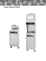
Models CF 200 and CF 200-VH
Chester Fried A Division of Giles Enterprises, Inc.
P.O. Box 210247 • 2750 Gunter Park Drive West • Montgomery, AL 36121-0247 USA • (334) 272-3528
SERVICE HOTLINE 1-800-288-1555 (USA and Canada only) • FAX (334) 272-3561 • www.chesterfried.com
Form No. 60204 (7/98)
Safety Precautions
FOR YOUR SAFETY
!
DO NOT store or use gasoline or other flammable vapors and liquids in the vicinity of this
or any other appliance!
!
WARNING
Improper installation, adjustment, alteration, service or maintenance can cause property
damage, injury or death. Read the installation, operating, and maintenance instructions
thoroughly before installing or servicing this equipment.
POST IN A PROMINENT LOCATION
Table of Contents
I
Introduction . . . . . . . . . . . . . . . . . . . . . . . . . . . . . . . . . . . . . . . . . . . . . . . . . . . . . . . . . . . . . . . . . . . . . . . . . . . . . . . . . . . . . . . . . . . . . . . . . . . . . . . . . . . . . . . . . . . . . . 2
1
1-1
1-2
1-3
1-4
Installation . . . . . . . . . . . . . . . . . . . . . . . . . . . . . . . . . . . . . . . . . . . . . . . . . . . . . . . . . . . . . . . . . . . . . . . . . . . . . . . . . . . . . . . . . . . . . . . . . . . . . . . . . . . . . . . . . . . . . . . .
Installation Instructions . . . . . . . . . . . . . . . . . . . . . . . . . . . . . . . . . . . . . . . . . . . . . . . . . . . . . . . . . . . . . . . . . . . . . . . . . . . . . . . . . . . . . . . . . . . . . . . . . . . . . .
Removal of Fryer From Crate . . . . . . . . . . . . . . . . . . . . . . . . . . . . . . . . . . . . . . . . . . . . . . . . . . . . . . . . . . . . . . . . . . . . . . . . . . . . . . . . . . . . . . . . . . . . .
Ventilation of Fryers. . . . . . . . . . . . . . . . . . . . . . . . . . . . . . . . . . . . . . . . . . . . . . . . . . . . . . . . . . . . . . . . . . . . . . . . . . . . . . . . . . . . . . . . . . . . . . . . . . . . . . . . . . . .
Electrical Requirements . . . . . . . . . . . . . . . . . . . . . . . . . . . . . . . . . . . . . . . . . . . . . . . . . . . . . . . . . . . . . . . . . . . . . . . . . . . . . . . . . . . . . . . . . . . . . . . . . . . . .
2
Operating Instructions. . . . . . . . . . . . . . . . . . . . . . . . . . . . . . . . . . . . . . . . . . . . . . . . . . . . . . . . . . . . . . . . . . . . . . . . . . . . . . . . . . . . . . . . . . . . . . . . . . . . . 6
3
3-1
3-2
3-3
3-4
Fryer Components and Their Functions . . . . . . . . . . . . . . . . . . . . . . . . . . . . . . . . . . . . . . . . . . . . . . . . . . . . . . . . . . . . . . . . . . . . . . . . 8
Control Panel . . . . . . . . . . . . . . . . . . . . . . . . . . . . . . . . . . . . . . . . . . . . . . . . . . . . . . . . . . . . . . . . . . . . . . . . . . . . . . . . . . . . . . . . . . . . . . . . . . . . . . . . . . . . . . . . . . . . . . 9
Lower Cabinet Area. . . . . . . . . . . . . . . . . . . . . . . . . . . . . . . . . . . . . . . . . . . . . . . . . . . . . . . . . . . . . . . . . . . . . . . . . . . . . . . . . . . . . . . . . . . . . . . . . . . . . . . . . . . . 11
Air Cleaning Components . . . . . . . . . . . . . . . . . . . . . . . . . . . . . . . . . . . . . . . . . . . . . . . . . . . . . . . . . . . . . . . . . . . . . . . . . . . . . . . . . . . . . . . . . . . . . . . . . . 13
Cooking Vessel . . . . . . . . . . . . . . . . . . . . . . . . . . . . . . . . . . . . . . . . . . . . . . . . . . . . . . . . . . . . . . . . . . . . . . . . . . . . . . . . . . . . . . . . . . . . . . . . . . . . . . . . . . . . . . . . . . . 15
4
4-1
4-2
4-3
Testing the Fryer. . . . . . . . . . . . . . . . . . . . . . . . . . . . . . . . . . . . . . . . . . . . . . . . . . . . . . . . . . . . . . . . . . . . . . . . . . . . . . . . . . . . . . . . . . . . . . . . . . . . . . . . . . . . . . . 16
Proper Control Settings for Check Out . . . . . . . . . . . . . . . . . . . . . . . . . . . . . . . . . . . . . . . . . . . . . . . . . . . . . . . . . . . . . . . . . . . . . . . . . . . . . . 16
Operational Check of Heating Elements. . . . . . . . . . . . . . . . . . . . . . . . . . . . . . . . . . . . . . . . . . . . . . . . . . . . . . . . . . . . . . . . . . . . . . . . . . . . 16
Operational Check-Out of the Filter Pump. . . . . . . . . . . . . . . . . . . . . . . . . . . . . . . . . . . . . . . . . . . . . . . . . . . . . . . . . . . . . . . . . . . . . . . . . 17
5
5-1
5-2
5-3
5-4
5-5
5-6
5-7
Preparing the Fryer for Operation . . . . . . . . . . . . . . . . . . . . . . . . . . . . . . . . . . . . . . . . . . . . . . . . . . . . . . . . . . . . . . . . . . . . . . . . . . . . . . . . . . 18
Fryer Boil-Out Procedure. . . . . . . . . . . . . . . . . . . . . . . . . . . . . . . . . . . . . . . . . . . . . . . . . . . . . . . . . . . . . . . . . . . . . . . . . . . . . . . . . . . . . . . . . . . . . . . . . . . . 18
Cleaning of Filter Pan/Replacement of Filter Paper . . . . . . . . . . . . . . . . . . . . . . . . . . . . . . . . . . . . . . . . . . . . . . . . . . . . . . . . . . . 23
Cleaning Considerations for Chester Fried Ventless Hood Fryers . . . . . . . . . . . . . . . . . . . . . . . . . . . . . . . . . . . 25
Removal and Replacement of Filters . . . . . . . . . . . . . . . . . . . . . . . . . . . . . . . . . . . . . . . . . . . . . . . . . . . . . . . . . . . . . . . . . . . . . . . . . . . . . . . . . 26
Operating the Fryer’s Controls for Cooking . . . . . . . . . . . . . . . . . . . . . . . . . . . . . . . . . . . . . . . . . . . . . . . . . . . . . . . . . . . . . . . . . . . . . . . 28
Filtering the Fryer . . . . . . . . . . . . . . . . . . . . . . . . . . . . . . . . . . . . . . . . . . . . . . . . . . . . . . . . . . . . . . . . . . . . . . . . . . . . . . . . . . . . . . . . . . . . . . . . . . . . . . . . . . . . . . . 29
Inspection and Testing of Safety Interlocks . . . . . . . . . . . . . . . . . . . . . . . . . . . . . . . . . . . . . . . . . . . . . . . . . . . . . . . . . . . . . . . . . . . . . . . 30
6
6-1
6-2
6-3
6-4
6-5
6-6
6-7
6-8
6-9
6-10
Fire Suppression System . . . . . . . . . . . . . . . . . . . . . . . . . . . . . . . . . . . . . . . . . . . . . . . . . . . . . . . . . . . . . . . . . . . . . . . . . . . . . . . . . . . . . . . . . . . . . . . . 32
System Description . . . . . . . . . . . . . . . . . . . . . . . . . . . . . . . . . . . . . . . . . . . . . . . . . . . . . . . . . . . . . . . . . . . . . . . . . . . . . . . . . . . . . . . . . . . . . . . . . . . . . . . . . . . . 32
Installation . . . . . . . . . . . . . . . . . . . . . . . . . . . . . . . . . . . . . . . . . . . . . . . . . . . . . . . . . . . . . . . . . . . . . . . . . . . . . . . . . . . . . . . . . . . . . . . . . . . . . . . . . . . . . . . . . . . . . . . . . . 32
Remote Manual Pull Station. . . . . . . . . . . . . . . . . . . . . . . . . . . . . . . . . . . . . . . . . . . . . . . . . . . . . . . . . . . . . . . . . . . . . . . . . . . . . . . . . . . . . . . . . . . . . . . 33
Maintenance . . . . . . . . . . . . . . . . . . . . . . . . . . . . . . . . . . . . . . . . . . . . . . . . . . . . . . . . . . . . . . . . . . . . . . . . . . . . . . . . . . . . . . . . . . . . . . . . . . . . . . . . . . . . . . . . . . . . . . . 33
Service . . . . . . . . . . . . . . . . . . . . . . . . . . . . . . . . . . . . . . . . . . . . . . . . . . . . . . . . . . . . . . . . . . . . . . . . . . . . . . . . . . . . . . . . . . . . . . . . . . . . . . . . . . . . . . . . . . . . . . . . . . . . . . . . 34
Assembly, 3/8" Black Pipe . . . . . . . . . . . . . . . . . . . . . . . . . . . . . . . . . . . . . . . . . . . . . . . . . . . . . . . . . . . . . . . . . . . . . . . . . . . . . . . . . . . . . . . . . . . . . . . . . . . . 36
Assembly, 1/2" EMT Conduit (Stage 1) . . . . . . . . . . . . . . . . . . . . . . . . . . . . . . . . . . . . . . . . . . . . . . . . . . . . . . . . . . . . . . . . . . . . . . . . . . . . . . . . 38
Assembly, 1/2" EMT Conduit (Stage 2) . . . . . . . . . . . . . . . . . . . . . . . . . . . . . . . . . . . . . . . . . . . . . . . . . . . . . . . . . . . . . . . . . . . . . . . . . . . . . . . . 40
Assembly, 1/2" EMT Conduit (Stage 3) . . . . . . . . . . . . . . . . . . . . . . . . . . . . . . . . . . . . . . . . . . . . . . . . . . . . . . . . . . . . . . . . . . . . . . . . . . . . . . . . 42
Assembly, Manual Pull . . . . . . . . . . . . . . . . . . . . . . . . . . . . . . . . . . . . . . . . . . . . . . . . . . . . . . . . . . . . . . . . . . . . . . . . . . . . . . . . . . . . . . . . . . . . . . . . . . . . . . . 44
3
3
5
5
5
Table of Contents
7
7-1
7-2
7-3
7-4
7-5
7-6
7-7
Cooking Instructions. . . . . . . . . . . . . . . . . . . . . . . . . . . . . . . . . . . . . . . . . . . . . . . . . . . . . . . . . . . . . . . . . . . . . . . . . . . . . . . . . . . . . . . . . . . . . . . . . . . . . . . . 45
Marinating Process. . . . . . . . . . . . . . . . . . . . . . . . . . . . . . . . . . . . . . . . . . . . . . . . . . . . . . . . . . . . . . . . . . . . . . . . . . . . . . . . . . . . . . . . . . . . . . . . . . . . . . . . . . . . . 45
Batter Dipped Seasoning . . . . . . . . . . . . . . . . . . . . . . . . . . . . . . . . . . . . . . . . . . . . . . . . . . . . . . . . . . . . . . . . . . . . . . . . . . . . . . . . . . . . . . . . . . . . . . . . . . . 45
Breading . . . . . . . . . . . . . . . . . . . . . . . . . . . . . . . . . . . . . . . . . . . . . . . . . . . . . . . . . . . . . . . . . . . . . . . . . . . . . . . . . . . . . . . . . . . . . . . . . . . . . . . . . . . . . . . . . . . . . . . . . . . . . 46
Loading the Chicken . . . . . . . . . . . . . . . . . . . . . . . . . . . . . . . . . . . . . . . . . . . . . . . . . . . . . . . . . . . . . . . . . . . . . . . . . . . . . . . . . . . . . . . . . . . . . . . . . . . . . . . . . . . 46
Using IQF Chicken. . . . . . . . . . . . . . . . . . . . . . . . . . . . . . . . . . . . . . . . . . . . . . . . . . . . . . . . . . . . . . . . . . . . . . . . . . . . . . . . . . . . . . . . . . . . . . . . . . . . . . . . . . . . . . 47
Stirring the Chicken . . . . . . . . . . . . . . . . . . . . . . . . . . . . . . . . . . . . . . . . . . . . . . . . . . . . . . . . . . . . . . . . . . . . . . . . . . . . . . . . . . . . . . . . . . . . . . . . . . . . . . . . . . . . 47
Preparing the Potatoes . . . . . . . . . . . . . . . . . . . . . . . . . . . . . . . . . . . . . . . . . . . . . . . . . . . . . . . . . . . . . . . . . . . . . . . . . . . . . . . . . . . . . . . . . . . . . . . . . . . . . . . 47
8
8-1
8-2
Troubleshooting . . . . . . . . . . . . . . . . . . . . . . . . . . . . . . . . . . . . . . . . . . . . . . . . . . . . . . . . . . . . . . . . . . . . . . . . . . . . . . . . . . . . . . . . . . . . . . . . . . . . . . . . . . . . . . . 49
Temperature Control System with Cooking Computer . . . . . . . . . . . . . . . . . . . . . . . . . . . . . . . . . . . . . . . . . . . . . . . . . . . . . 49
Automatic Basket Lift and Oil Filtration System . . . . . . . . . . . . . . . . . . . . . . . . . . . . . . . . . . . . . . . . . . . . . . . . . . . . . . . . . . . . . . . . 51
9
Parts . . . . . . . . . . . . . . . . . . . . . . . . . . . . . . . . . . . . . . . . . . . . . . . . . . . . . . . . . . . . . . . . . . . . . . . . . . . . . . . . . . . . . . . . . . . . . . . . . . . . . . . . . . . . . . . . . . . . . . . . . . . . . . . . . . . 52
10
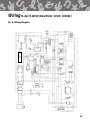
Wiring Diagrams. . . . . . . . . . . . . . . . . . . . . . . . . . . . . . . . . . . . . . . . . . . . . . . . . . . . . . . . . . . . . . . . . . . . . . . . . . . . . . . . . . . . . . . . . . . . . . . . . . . . . . . . . . . . . . . 59
Introduction
I
Introduction
Congratulations on the purchase of your new Chester Fried Electric Fryer. With proper care and maintenance this unit could provide you with years of trouble-free service.
To help protect your investment in this state -of-the-art cooking equipment, we recommend you take a
few moments to familiarize yourself with the installation, cleaning and maintenance procedures contained
in this manual. Adherence to these recommended procedures minimizes the potential for costly “DownTime” and equipment repairs.
Parts Ordering and Service Information
If you require repair or assistance, please contact your local independent distributor. If you require further
assistance please contact our corporate office in Montgomery, Alabama at 1-800-288-1555.
Please have the following information available when calling for assistance. It may be helpful to record
this information in the blanks provided below for a quick reference.
1. Model Number: ______________________________________________________________________
2. Serial Number: ______________________________________________________________________
3. Phase: ______________________________________________________________________________
4. Voltage: _____________________________________________________________________________
5. Nature of Problem: ___________________________________________________________________
The above information can be found on the Rating Plate located on the fryer’s back.
2
Installation Instructions
1 - 1 Installation Instructions
This section provides a summary of the procedures necessary for proper installation of your new Chester
Fried Electric Fryer. To prevent personal injury or equipment damage, please ensure the following steps
are taken:
!
CAUTION
For your safety DO NOT store or use gasoline or other flammable vapors and liquids in the
vicinity of this or any other appliances!
1. Keep the appliance and surrounding area free and clear from combustible materials. {(3")(7.6cm) for
Fryer and (16")(46cm) for Ventless Hood.}
2. Please retain this manual for future reference.
3. Please note wiring diagrams for this appliance are located in the rear of this manual. Ensure the wiring
diagram which you consult corresponds to the model being operated.
4. Please ensure this appliance is electrically grounded in accordance with local codes, or in the absence of
local codes, with the National Electrical Code, ANSI/NFPA NO. 70-1984.
5. Please provide adequate room for servicing and proper operation of this appliance. Also, provide
adequate ventilation in the operating area where necessary.
6. Always consult with an electrician or other qualified individual prior to installation.
7. Ensure voltage and amperage supplied to the unit are as specified on the fryer’s rating plate.
8. Make sure this unit is in a secure position and will not move. Locking casters are supplied on this unituse them!
* 9. Based on local codes, room size and appliances in use, exhaust ventilation may be required. This often
can be accomplished by the installation of an exhaust fan, which exhaust 200 cfm/lineal ft. of hood, in
the room in which the hood is installed. To determine the requirements for your installation, supply the
HVAC dealer the following information:
* a. The Hood exhausts between 210 to 280 cfm of air.
b. The average temperature of the air being exhausted from the hood, after four (4) hours of continuous
frying, is approximately 90°F (32°C)
* 10. This appliance is to be installed, used and maintained in accordance with the Standard for Ventilation
Control, and Fire Protection of Commercial Cooking Operations, NFPA 96-1994.
* 11. DO NOT obstruct the exhaust air outlet. (Maintain a minimum clearance of 12" (30.5cm) of exhaust outlet
and ceiling or obstruction; (18") (45.7cm) is recommended.)
12. The NFPA recommends a Smoke Detector be installed above a recirculating Hood System.
* Ventless hood models only.
3
Installation Instructions
NOTE:
The decibel level of the hood when operating is approximately 65dB’s
!
IMPORTANT NOTE:
The Exhaust Fan in Ventless Hood Fryers should be lubricated at least every six (6) months! Call Technical
Services at 1-800-288-1555 for instructions.
!
DO NOT Modify, Alter or Add Attachments to This Equipment!
The above steps will help to ensure safe and proper installation of your fryer. If you have any questions
concerning these procedures, contact your local Chester Fried distributor or other qualified service person.
4
Installation Instructions
1 - 2 Removal of Fryer from Crate
Your Chester Fried Electric Fryer may arrive enclosed by a wooden crate. If your unit arrived uncrated, go
to Section 1-3. The Fryer is secured to a wooden platform by means of high-tensile strength strapping.
1.
Carefully cut and remove the plastic shipping wrap and the strapping mentioned above.
2.
Use pliers to loosen wire hooks which secure the wooden crate around the fryer. CF-200 and
CF-200-VH fryers are enclosed in a two-piece crate. Remove the wooden crates.
3.
Carefully remove the fryer from the shipping platform. Your new fryer is extremely heavy and great
care should be taken in lifting or moving the unit to prevent personal injury or equipment damage.
1 - 3 Ventilation of Fryers
Your new Chester Fried Fryer has been designed either for operation beneath a traditional exhaust hood or
in the case of Ventless Hood Fryers, as a self-contained unit requiring no hood or duct system. We strongly recommentd you consult a professional ventilation or heating and air conditiong company for assistance
in designing a hood for those models which require an exhaust system.
IMPORTANT NOTE
Guidelines for proper ventilation system requirements may differ. Always consult with local authorities to
ensure compliance.
1 - 4 Electrical Requirements
!
WARNING
Fryers must be adequately and properly grounded. Improper grounding may result in
electrical shock. Always refer to your local electrical code to ensure proper grounding of
this or any other electrical equipment. Always consult with an electrician or other qualified
service person to ensure breakers and wiring are of sufficient rating and gauge for the
equipment being operated.
Chester Fried Electric Fryers are available from the factory wired for 208 or 240 volts, and single phase,
50/60HZ. service. Check the rating plate on the rear of the fryer to determine the correct power supply.
5
Operating Instructions
2 - 1 Operating Instructions
For your safety, please observe the following precautions when operating your Chester Fried Fryer:
1.
Ensure the fry kettle is positioned in a secure, safe location with the casters in the locked position.
2.
Consult an electrician to ensure all electrical specifications have been met and the unit is properly
grounded. The wiring diagrams contained in this manual should aid your electrician in the
installation of your fryer.
3.
Due to the high temperature of shortening in your fryer during cooking, it is extremely important the
user exercise caution in operation this equipment to avoid personal injury.
6
Models CF-200 and CF-200 VH
7
Fryer Components and Their Functions
3
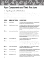
Fryer Components and Their Functions
The following section is designed to introduce you to the controls used in operating this equipment.
DO NOT attempt operation of this unit until you have located each control discussed and fully understand
their intended function. Failure to do so may result in improper operation resulting in equipment damage or
personal injury to the operator.
Please review this section carefully before proceeding any further.
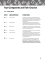
ITEM
DESCRIPTION
FUNCTION
1. Fig. 1
Power Switch
The Power Switch is a two-position switch. Move the switch
upward to the “ON” position for operation.
2. Fig. 1
Cook/Filter Selector Switch
The Selector Switch is a three-position switch which is used
to select either the cook, off or filter mode of operation. The
fryer’s Heating Elements will only operate in the “COOK”
position. The switch should be placed in the “FILTER”
position to filter the shortening which will allow the pump to
operate.
3. Fig. 1
Mechanical Cooking Timer
The Cooking Timer is used in conjunction with the Elevator
Switch to provide timed cooking and removal of food
products from the fryer by the elevator lift. To accomplish
this, ensure the COOK/FILTER Switch is in the “COOK”
position. At the end of the selected cooking time, the food
products and fry basket will be automatically lifted from the
fryer by the elevator lift.
* 4. Fig. 1
“ON” Indicator Light
The “ON” Indicator Light is on when the Electronic Air
Cleaner (EAC) power supply is on.
* 5. Fig. 1
“Wash” Indicator Light
The “Wash” Indicator Light is on when the EAC becomes
excessively dirty. Do not use the wash light as a signal for
routine cleaning of the EAC. This practice will significantly
decrease the life of the Charcoal Filter. Clean the EAC daily for
best performance and extended Charcoal Filter life.
* 6. Fig. 1
“Check” Indicator Light
The “Check” Indicator Light is on when the EAC becomes
shorted. (EAC needs cleaning or repair.)
* 7. Fig. 1
Filter Missing Light
The Filter Missing Light is on when the Grease Baffle Filter or
the Charcoal Filter are not properly positioned.
8. Fig. 1
Power Indicator Light
The Green Power Light is on whenever the fryer’s Master
Power Switch is in the “ON” position.
9. Fig. 1
Heat Indicator Light
The Orange Heat Indicator Light will be on when the fryer’s
Heating Elements are operating. When the selected operating
temperature is reached, the light will go off.
8
Fryer Components and Their Functions
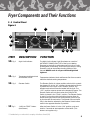
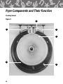
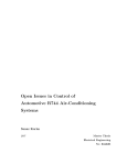
3 - 1 Control Panel
Figure 1
11
12
2
7
8
9
10
1
*
3
4
5
6
ITEM
DESCRIPTION
FUNCTION
10. Fig 1
High-Limit Indicator
The High-Limit Indicator Light illuminates as a result of
AUTOMATIC POWER SHUT-OFF of the fryer’s Heating
Elements by the built-in solid-state control circuit as a safe
guard against overheating. Should this light come on during
operation, refer to the trouble-shooting section of this
manual. NEVER cook in a fryer with the High-Limit
Light on!
11. Fig. 1
Temperature Indicator Knob
and Remote Set Pot
Temperature Indicator Knob and Remote Set Pot are used to
select the desired cooking temperature.
12. Fig. 1
Elevator Switch
The Elevator Switch is a three-position switch which controls
the elevator lift. In the “UP” position, the mechanism lifts the
fry basket out of the fryer. In the “DOWN” position, the
elevator mechanism lowers the basket into the fryer. The
“OFF” position removes power to the elevator lift motor. The
Elevator Switch will only work when the COOK/FILTER
Switch is placed in the “COOK” position. The Elevator Switch
is used in conjunction with the cooking timer to allow for
timed cooking and removal of food products from the fryer
by the elevator lift mechanism. The elevator lift must travel
fully in the direction selected by the Elevator Switch before
travel in the opposite direction is possible.
13. Fig 1
“HOLD to START” Button
(Not Shown)
After the Power Switch is in the “ON” position, push and
hold for 5 seconds to start operation of the Hood. (This
button Los Angeles only.)
* Provided only on units which employ a Ventless Hood (VH)
9
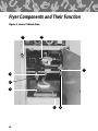
Fryer Components and Their Function
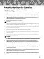
Figure 2 Lower Cabinet Area
8
2
5
3
6
1
7
10
4
Fryer Components and Their Function
3 - 2 Lower Cabinet Area
ITEM
DESCRIPTION
1. Fig. 2
Filter Pan Hold-Down
Bracket and Latches
FUNCTION
The Hold-Down Bracket is contained in the Filter Pan and
serves to ensure the filter paper is held tightly in place by
means of the four locking latches. The fryer’s filtering action
will be reduced or eliminated if these latches are not properly
secured.
2. Fig. 2
T-Handle/Drain Valve
Turning this T-Handle counter-clockwise allows shortening to
drain from the frying vessel into the Filter Pan. Open the
valve slowly to avoid burns from splashing of hot oil.
Always ensure the valve is closed prior to adding shortening.
Your fryer will not operate if this Drain Valve is not
completely closed. (i.e., clockwise)
3. Fig. 2
Drain Valve Pipe-Drain
This Pipe-Drain attaches to the Drain Valve and helps to
minimize splashing of hot oil when the fry-kettle is filtered or
drained. The Pipe-Drain must be removed before sliding the
Filter Pan out of the fryer. Always use insulted gloves to
remove this hand tightened pipe.
4. Fig 2
Quick Disconnect for
Oil Discharge Wand
5. Fig 2
Diverter Valve
6. Fig 2
Quick Disconnect
For Filter Pan
This Quick-Disconnect Fitting is used in conjunction with the
oil discharge wand to remove oil from the fryer that is to be
discharged.
The Diverter Valve may be identified by its colored lever-type
handle. During a normal operation it should be positioned so
it points outward toward the operator. For removal of oil with
the discharge hose connected, the Diverter Valve handle
should be turned inward and to the operator’s right. After
removal of oil for discard it should be returned to its normal
position pointing toward the operator. Details of the oil
procedure are covered in the operations of this manual.
This Quick Disconnect fitting serves to connect the hose from
the Filter Pan to the fryer’s oil return lines. The hose must be
disconnected at this fitting prior to sliding the Filter Pan
outward for cleaning or removal. The fitting is operated by
pushing upward on the insulating ring and exerting
downward pressure on the connecting end of the hose. For
reconnection, push upward on the insulating ring while
inserting the hose. Release the insulating ring when the hose
fitting is fully inserted to lock it in position.
11
Fryer Components and Their Function
ITEM
DESCRIPTION
FUNCTION
7. Fig. 2
Filter Pan
The Filter Pan contains the filter paper which serves
to remove breading and other impurities from the oil
during the filtering procedure. Oil is drained into the
Filter Pan where the fryer’s pumping action draws it
through the filter paper and returns it to the cooking
vessel by way of the Filter Pan Hose.
8.
Manual Pull (VH series only)
Figure 3
The Manual Pull can be used to manually operate the
fryer’s built-in fire extinguishing system.
Upper Hood Area Showing Location of Components.
(VH) models only
1
2
12
Fryer Components and Their Function
3 - 3 Air Cleaning Components. Use with (VH) models.
Figure 4
1
2
3
ITEMS DESCRIPTION
1. Fig. 3& 4
2. Fig. 3& 4
3. Fig. 4
Charcoal Filter
Replaced MONTHLY
Electronic Air Cleaner (EAC)
Cleaned DAILY
Baffle Filter Cleaned DAILY
FUNCTION
The Charcoal Filter helps to remove odor generated during
cooking. This comprises the third and final stage of the air
filtration system used in the Ventless Hood System. It is
mounted in a slide-rack directly above the EAC. Disconnect
fryer power before removing this filter. NEVER
attempt to clean this filter. Keep a spare filter on hand
(Chester Fried 31137) for quick change-out when needed!
The EAC is an electrical device which removes grease vapor
and smoke generated by the fryer during cooking. The access
panel on the front of the upper hood portion must be
removed to allow for access to the cell. Power must be
turned OFF to the fryer before removing the EAC for
cleaning. The EAC should be cleaned daily.
The Baffle Filter is the first stage of the three-part grease
extraction and air-cleaning system found on these units. It is
easily removed for daily cleaning. DO NOT remove the
Baffle Filter while the fryer is operating to prevent
contact with electrical parts and avoid electrical
shock.
13
Fryer Components and Their Function
Cooking Vessel
Figure 5
6
1
5
3
2
4
14
Fryer Components and Their Function
3 - 4 Cooking Vessel
ITEM
DESCRIPTION
FUNCTION
1. Fig. 5
Oil Temp Probe
The Oil Temp Probe senses oil temperature during
fryer operation for temperature control. Its signal is
directed to the fryer’s control unit for comparison with
the temperature selected by remote set-pot on the
operator panel.
2. Fig. 5
Heating Element
The Heating Element heats the shortening to the
selected temperature. Always maintain the cold oil
level above the Heating Elements to prevent oil fires!
3. Fig. 5
Basket Carrier
The Basket Carrier is inserted into the elevator shaft
and allows for positioning and control of the basket in
the fryer using the elevator lift.
4. Fig. 5
Oil Return Inlet
The Oil Return Inlet serves to return oil to the frying
vessel following filtering.
5. Fig. 5
High-Limit Probe
The High-Limit Probe senses oil temperature during
fryer operation for oil overheating. If the sensor
detects an oil temperature in excess of 424°F (218°C),
the solid state control system will turn off power to
the Heating Elements.
6. Fig. 5
Oil Level Line
The Oil Level Line marks the proper level of HOT
shortening. When COLD, the shortening will be
approximately 3⁄4" (1.9cm) below the Oil Level Line.
The proper shortening level is important and
should be checked a minimum of once per day.
15
Testing the Fryer
4
Testing the Fryer
We at Chester Fried take pride in the quality of out workmanship. Every effort has been made to ensure
your unit is in good operating condition when you receive it. Each unit must pass a rigorous quality control
test prior to shipment. To further ensure optimum operation of your new unit we recommend a brief operational check-out of your new fryer.
!
CAUTION
Before attempting to operate the unit, refer to Section 3 to familiarize yourself with the
various control functions. Once you have read and fully understand Section 3, please
follow the steps below precisely in order to prevent equipment damage or malfunction.
4 - 1 Proper Control Settings for Check-Out
1.
Place all switches in the “OFF” position.
2.
Remove Fryer lid.
3.
Remove the baskets or other accessory items from the fry-kettle.
4.
Turn on the circuit breaker which supplies power to the unit.
5.
Place the fryer’s main Power Switch to “ON”. The green power light should be illuminated. If the
power light fails to illuminate, refer to the appropriate section of the troubleshooting guide. If the
green power light illuminates, proceed to the next step.
4 - 2 Operational Check of Heating Elements
This step is designed to ensure your fryer’s Heating Elements are functioning.
!
WARNING
DO NOT touch the Heating Elements during this portion of the check-out. The Heating
Elements are very hot and skin contact with them may result in severe burns.
1.
Wipe the dry cool Heating Elements with a wet sponge.
!
CAUTION
This portion of the check-out requires the elements be activated. DO NOT operate the
elements for more than 10 seconds without them being fully covered by shortening.
Failure to observe this precaution may result in damage to the Heating Elements.
16
Testing the Fryer
2.
With the fryer’s lid removed, briefly turn the Selector Switch to the “COOK” position (max. 10 sec.).
Then return it to the “OFF” position.
3.
The wet Heating Elements should dry within 15 seconds after fryer element shut-off signifying heat.
4.
If the Heating Elements do not appear operational, refer to the Troubleshooting guide.
5.
If the Heating Elements are operational, clean the fryer as described under instructions for the BoilOut procedure described in this manual in Section 5-1.
6.
After thorough cleaning, fill fry pot to proper level with shortening.
4 - 3 Operational Check-Out of the Filter Pump
1.
Open the fryer’s front door.
2.
Disconnect the Filter-Pan Hose by lifting the insulating ring on the Quick-Disconnect and pull the
hose out of this fitting
!
CAUTION
The following step requires starting of the fryer’s filter pump in a “DRY” condition. The
pump should only be operated for a few seconds in this manner or damage to the unit will
occur.
3.
Place the fryer’s Power Switch to the “ON” position.
4.
Place your palm over the Quick-Disconnect at the point where the hose from the filter-pan connects.
5.
Briefly place the Selector Switch in the “FILTER” position. If suction is felt on the hand covering the
Quick-Disconnect, the pump is operational. If the above steps are followed and no suction is felt,
consult the troubleshooting guide.
17
Preparing the Fryer for Operation
5
Preparing the Fryer for Operation
Your new fryer should be cleaned thoroughly before actual cooking takes place. To accomplish this, follow
the procedure described in the following Boil-Out Procedure section.
5 - 1 Fryer Boil-Out Procedure
This section describes the cleaning process for your fryer known as the “Boil-Out”. A “Boil-Out” should
be performed on the new equipment prior to actual cooking and every time shortening is removed from
the fryer for cleaning of the fry-kettle and refill with fresh shortening.
!
WARNING
Please perform the steps of this procedure as described to avoid possible equipment dam
age, violation of warranty provisions or personal injury.
1.
Always use thermal oven mitts during this procedure to protect skin from burns due to splashing of
hot liquids.
2.
If you are performing a “Boil-Out” on a new fryer which DOES NOT contain shortening, go to Step
19, otherwise proceed to Step 3.
3.
If the shortening in the fryer is not in a heated state (at least 200°F) (93°C), go to Step 4. If the fryer
has been in operation and the shortening is in a heated state, place the Selector Switch in the “OFF”
position and allow the shortening to cool for 3 minutes before continuing.
4.
If the shortening in the fryer is “cold”, that is at room temperature, you must first heat the
shortening briefly so it is liquid enough to be removed by the fryer’s filter system. To do this, turn the
main Power Switch to “ON” and the Selector Switch to “COOK.” Set the Controller temp. to 200°F
(93°C) and heat the oil until the orange heat indicator light goes off. Stir the shortening well to
ensure it is fully dissolved. Stirring may cause the orange heat light to come on again briefly. When
the orange light goes off again, place the Selector Switch in the “OFF” position and go to Step 5.
5.
Ensure the Selector Switch is in the “OFF position before proceeding.
!
WARNING
The next step of this procedure requires the shortening be drained from the fry-kettle into
the fryer’s Filter Pan. Failure to ensure that the fryer’s Selector Switch is in the “OFF”
position prior to draining may result in fire on the exposed Heating Elements. Always
ensure the Selector Switch is in the proper position
6.
18
Slowly open the T-Handle located on the drain beneath the fry-kettle. The drain is opened by turning
it counter-clockwise. Use care in opening this valve to avoid being splashed by hot oil. (You may find
the drain requires insertion of the smaller brush enclosed with the fryer in order to free the valve of
breading which may clog it. The brush should be inserted from above. Be careful not to puncture the
filter paper when using this brush.)
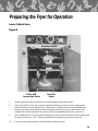
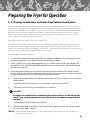
Preparing the Fryer for Operation
Lower Cabinet Area
Figure 6
Selector Switch
Filter Pan
Connection Point
Diverter
Valve
7.
Ensure the Diverter Valve is positioned so its handle points toward the operator.
8.
Place Pump Switch in the “ON” position and allow shortening to return to the fry-kettle and out
through the drain. Use this opportunity to “Wash-Down” breading which has accumulated in the
bottom of fry-kettle. Use the larger pot brush supplied with the fryer to help “Wash Down” this
material into the filter-pan below. Use care to avoid being splashed and burned by the hot oil.
9.
After “Washing Down” all accumulated breading and crumbs from the bottom of the fry-kettle, place
the Pump Switch in the “OFF” position and allow the shortening to drain into the Filter Pan.
10.
Turn the Diverter Valve Handle on the Drain Valve clockwise to close.
19
Preparing the Fryer for Operation
11.
!
Position an appropriate receptacle for the oil you are to discard near the front of the fryer.
Remember, you will be removing approximately 4 gallons (15.2L) of shortening. Please ensure the
container which you have selected will contain all of the shortening. For ease in handling you may
find it helpful to use more than a single container. The shortening you will remove weighs about
26lbs. (11.8kg) and is still very hot. Placing the discarded shortening in two or more containers for
removal makes for a lighter load and decreases the possibility of injury by splashing. We
recommend our Oil Caddy (Part #79229A) for this purpose.
WARNING
Always ensure the containers which are used for this step will safely hold hot oil. Plastic is
generally not safe as it may melt and break. Metal containers which do not leak are
preferable to containers made of other materials. Failure to exercise the above precautions
may result in serious injury.
12.
Connect the Discharge Drain Hose to the Quick Disconnect located beside the Diverter Valve. Always
ensure the hose coupling is securely mated at the quick disconnected fitting.
13.
Turn the handle on the Diverter Valve to the left (Clockwise).
14.
Position the hand-held wand end of the discharge hose over the receptacle which you have
positioned to receive the HOT waste oil from the fryer. Always grasp the discharge hose by the
insulated sleeve near the wand end.
15.
Place the Selector Switch in the “FILTER” position and allow the fryer filter system to pump the HOT
waste oil out of the fryer through the drain hose.
16.
When all waste oil has been removed from the fryer, return the Selector Switch to the “OFF”
position.
17.
Return the diverter handle to its normal position so it points towards the operator.
18.
Disconnect the drain hose from the fryer at the Quick Disconnectfitting below the Diverter Valve.
Always hold both ends of the drain hose in an upright position to avoid spillage of residual oil which
may be trapped in the hose. Carefully drain the hose into the receptacle which contains the waste oil
from the fryer.
19.
Disconnect the Filter Pan from the fryer at the Quick Disconnect fitting located above and to-the-left
of the Filter Pan.
20.
Remove the pipe-drain from the fry-kettle Drain Valve threading it in a counter-clockwise direction.
21.
Slide the Filter Pan forward and carefully remove it for cleaning. NOTE: We recommend you use
Chester Clean or an alkaline based cleanser to clean the Filter Pan. Avoid liquid dish washing
detergents as they may leave residues which reduce shortening life.
22.
Ensure the Drain Valve is closed by turning the T-Handle fully clockwise.
23.
Fill the fryer with water to the Oil Level Line.
20
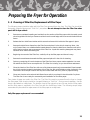
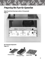
Preparing the Fryer for Operation
Filter Pan Shown with Drain Hose Attached
Figure 7
21
Preparing the Fryer for Operation
24.
Carefully add Chester Clean to the water following the directions on the container.
!
CAUTION
If you choose to use a cleaner other than Chester Clean to “Boil-Out” your fryer, pay close
attention to the instructions listed on the container. Many commercially available cleaners
are caustic chemicals which require special precautions for use. If used improperly, these
chemicals may cause damage to your fryer and potential injury to the user.
25.
Set Thermostat to 200°F (93°C).
!
CAUTION
DO NOT under any circumstances leave the fryer unattended during this procedure as heat
must be carefully monitored to prevent the fry-kettle from overflow due to boiling.
Overflow of the fry-kettle may result in serious equipment damage. In the event of near
boil over, flip the Power Switch off!
26.
Set the Selector Switch in the “COOK” position.
27.
Heat the cleaning solution for 30 minutes. Scrub the interior of the fry-kettle with the large pot brush
during this period to remove build-up.
28.
Flip Selector Switch to the off position.
29.
Position a heat resistant pail beneath the Drain Valve at the bottom of the fry kettle. Slowly open the
valve by turning the T-Handle counter-clockwise. Drain the cleaning solution from the fryer. Be
careful not to overfill the container which will hold the cleaning solution drained from the fryer.
30.
Close the Drain Valve by turning the T-Handle fully in a clockwise position.
31.
Rinse the inside of the fry-kettle with fresh water and repeat the drain procedure described in
step 29.
32.
Mop out excess water from the fryer pot with a dry cloth.
33.
Close the Drain Valve again.
34.
Replace Filter Pan after thorough cleaning.
IMPORTANT NOTE
Do Not pump “Boil-Out” through filter pump. Doing so can damage pump and void warranty.
35.
22
Fill fryer with shortening to the proper level. Shortening should reach the Oil Level Line when the oil
is HOT.
Preparing the Fryer for Operation
5 - 2 Cleaning of Filter Pan/Replacement of Filter Paper
The following steps should be taken with the Filter Pan removed from the fryer. The Filter Pan should be
thoroughly cleansed during each “Boil Out” procedure. Do not attempt to clean the Filter Pan when
pan is still in fryer cabinet.
1.
Remove accumulated breading and residue from the surface of the filter paper with the metal crumb
shovel supplied with the fryer. Remove residue from the small edge which surrounds the Hold-Down
frame.
2.
Release the four Hold-Down latches which secure the frame which holds the filter paper in place.
3.
Remove the Hold-Down frame from the Filter Pan and place it in the sink for cleaning. Note - Use
only Chester Clean or a suitable alkaline based cleaner to clean the Hold-Down frame as well as the
other interior surfaces and components of the Filter Pan. Liquid dish washing detergents may leave
residues which reduce shortening life.
4.
Beginning at one end of the Filter Pan, carefully roll up the filter paper and throw it away.
5.
Remove the metal weave beneath the filter paper and place it in the sink for cleaning.
6.
Drain any remaining oil from the bottom of the Filter Pan into a proper waste receptacle. You must
lift and tilt the Filter Pan to accomplish this. The Filter Pan is heavy, so you should have assistance.
7.
Clean the interior of the Filter Pan with one of the cleaners previously recommended. Clean beneath
the oil pick-up tube located in the bottom of the Filter Pan with a knife blade or other similar thin, flat
instrument. Rinse the pan interior and mop out excess water with a dry cloth or paper toweling.
8.
Clean and rinse the wire rack and Hold-Down frame which you placed in the sink earlier. Dry them.
The Filter Pan is now ready for re-assembly and installation of new filter paper.
Two sheets of paper are used in the Filter Pan. The Filter Pan must be removed from the fryer to change
the filter paper. Both sheets should be changed following a “Boil-Out.” During normal operation, the top
sheet is discarded on a daily basis. The bottom sheet is then placed on top of a new sheet of filter paper
and the filter paper is replaced in the Filter Pan with the Hold-Down frame. The following simple steps
summarize the procedure for replacement of the filter paper on a daily basis.
Daily filter paper replacement is recommended!
23
Preparing the Fryer for Operation
Disassembled View of Filter Pan; All Models
Figure 9
(photo not available at this time)
Hold-down
Latch
Filter Pan
Hold-down
Frame
Filter Pan
Screen
IMPORTANT NOTE:
DAILY Filter Paper Replacement is Recommended!
Instructions for changing the Filter Paper:
1.
Remove the crumb and breading residue which surrounds the Hold-Down rack that secures the filter
paper in place.
2.
Remove crumbs and breading residue from the top sheet of filter paper with the metal crumb shovel
supplied with the fryer.
3.
Release the four Hold-Down latches on the frame assembly which secures the filter paper.
4.
Remove the Hold-Down Frame.
5.
Carefully remove the top sheet of filter paper by lifting its corner or edge and rolling it towards the
other end. Discard the paper.
6.
Lift the edge of the bottom sheet and slip a clean sheet of filter paper beneath it.
7.
Replace the Hold-Down rack above the filter paper and secure it with the four latches.
8.
Replace the filter pan in the fryer and secure its hose connection with the Quick Disconnectfitting.
24
Preparing the Fryer for Operation
5 - 3 Cleaning considerations for Chester Fried Ventless Hood System
Ventless hoods are designed to remove grease vapors from the cooking operations and re-circulate the
cleaned air. The catch and hold principal of the recirculating system means you must perform daily cleaning of the EAC and baffle filter. In addition, the Charcoal Filter, which helps remove offensive odors associated with cooking, must be changed every 30 days. Failure to replace or clean these filters in a timely
manner may result in unpleasant odors and poor performance by the air-cleaning section of the hood.
NOTE: Empty the Grease Cup at least once DAILY.
Cleaning the Baffle Filter and Electronic Air Cleaner (EAC)
The most efficient air cleaning performance your new Ventless Hood can offer is yours when you clean
the baffle filter and EAC after every days use! Costs when using the Chester Fried “Portable Soak Tank
System” are massively reduced and speed is on your side. This small tank holds the EAC, cold water and
degreaser. It only needs to be changed monthly in most cases.
Recommended Cleaning Procedures:
1.
CLEAR MAGIC degreaser for the Portable Soak Tank System is available at your local retail store in the
automotive department. A one-gallon container will last 60 days or more!
2.
Empty 1⁄2 gallon (1.9L) of Clear Magic degreaser into your Chester Fried Soak Tank and add about 6.5
gallons (25L) of COLD WATER. CLEAR MAGIC/WATER mixture should cover EAC. Add additional water
at this time to cover EAC.
3.
At the end of each cooking day, remove EAC and gently lower into the Soak Tank. Let soak for 10-20
minutes. Please note the EAC is lowered by holding the red or white terminal board instead of the metal
or plastic front handle (i.e. the 16" (41cm) EAC dimension goes vertical).
4.
After 10-20 minutes, lift EAC in the soak tank up and down 1-2" (2-5cm) in soak tank to help remove
grease residue.
5.
Slowly remove the EAC from the tank and rinse clean in sink using HOT WATER.
6.
Leave EAC in the sink to dry on end as placed in the soak tank.
!
CAUTION
Be careful not to bend the fins or break the ionizer wires on the EAC as this will prevent
the EAC from working properly and shut off the power to the appliance being used with
the hood.
7.
Re-install both parts at the beginning of each day.
8.
CHANGE SOAK TANK SOLUTION AT LEAST MONTHLY by dipping it out and into the sink. NEVER
LIFT THE SOAK TANK TO EMPTY.
*NOTE: Clean the Baffle Filter DAILY by simply spraying and rinsing residue from the filter with HOT
water and letting it air dry.
25
Preparing the Fryer for Operation
5 - 4 Removal and Replacement of Filters
To Replace the Charcoal Filter or clean the EAC, perform the following steps:
1.
Place the Ventless Hood System’s Power Switch in the “OFF” position.
!
WARNING
Failure to ensure the Selector Switch is in the “OFF” position during the procedure may
result in equipment damage, electrical shock and/or personal injury.
2.
Release the catch which secures the access panel located on the lower front portion of the hood
system. Remove the access panel.
3.
The Charcoal Filter is located directly above the EAC. Remove the Charcoal Filter by grasping it by
the edge and pulling outward. (See Figures 9 &10).
4.
Discard the used Charcoal Filter and install the replacement filter with the blue side facing the EAC.
IMPORTANT NOTE:
Never attempt to clean the Charcoal Filter. Keep a spare filter on hand (Chester Fried 31137) for quick
change-out when needed!
5.
Remove the EAC by grasping the handle and pulling outward. (Care should be given not to bend the
fins or break the ionizer wires.)
6.
After cleaning, reinstall the EAC with the ionizer facing down.
7.
To remove the Baffle Filter, push the front end of filter upward and slide toward front of the hood. Let
the back end of the filter down and remove filter from hood. (Use Caution when grasping filter by
openings to prevent being cut by sharp edges.)
8.
To replace Baffle Filter, reverse step 7. (Be sure to install filter so interlock arm is activated when the
filter is in place. Failure to do so will prevent the appliance from operating.)
26
Preparing the Fryer for Operation
Upper Hood Area Showing Location of Components
Figure 9
1
2
Air Cleaning Components
Figure 10
2
1
Charcoal Filter
Electronic Filter
Baffle Filter
3
27
Preparing the Fryer for Operation
5 - 5 Operating the Fryer’s Controls for Cooking
Before cooking with the fryer, ensure you have read and fully understand the intended functions of each
control used on the fryer. Detailed explanations are found in Section 3 of this manual.
1.
Fill fryer with shortening approximately 3⁄4" (1.9cm) below the oil level located at the back of the fry
kettle. The oil level line is for “Hot” shortening and additional shortening can be added after heating
if necessary.
2.
Place the fryer’s Power Switch in the “ON” position (the green power light should come on).
3.
Place the Selector Switch in the “COOK” position.
4.
Use the COOK key to select the desired cooking temperature. The Orange Heat Light will glow as the
oil is heated to the proper temperature. When the Orange Light goes out, stir the shortening
vigorously to ensure it is completely heated. Stir the shortening until the Orange Light comes on
again.
5.
When the Orange Light goes out for the second time, the shortening will be at the selected cooking
temperature.
6.
Properly secure the Fry Basket to the Basket Carrier mounted to the fryer’s elevator shaft.
7.
Push the elevator Down Key. This will lower the Basket into the heated shortening.
8.
Carefully drop breaded food product into Fry Basket. Avoid splashing hot shortening. Note - Food
products should be placed in the fry basket after it is lowered into the hot oil. This prevents them
from sticking together. If the products to be cooked are frozen, they can be placed in the Fry Basket
before lowering it into the shortening.
9.
Push the desired Menu Key on Electronic Timer to start the timing cycle.
10.
Place the fryer lid in its proper position on the fry-kettle. Note - If you are cooking products which are
not frozen, it is a good idea to remove the lid and stir the food with the stir paddle supplied with the
fryer when the stir alarm sounds. This will help keep the food products from sticking together.
11.
If you have removed the fryer lid to stir the food products, replace it and allow the cooking cycle to
be completed.
12.
At the expiration of the selected time, the basket will be automatically lifted from the fryer.
13.
Remove the lid, dump the fry basket into a suitable container (LT. 3 Pan Assembly Part #79592), and
prepare for the next load.
28
Preparing the Fryer for Operation
5 - 6 Filtering the Fryer
The fryer should be filtered after every 4th load.
1.
Use thermal oven mitts during this procedure to prevent burns from hot oil and metal
surfaces of the fryer.
2.
Ensure filter paper (2 pieces) is properly positioned in the Filter Pan as described in Section 4-2
under the section detailing replacement of the filter paper.
3.
Place the Selector Switch in the “OFF” position.
!
WARNING
Failure to ensure the Selector Switch is in the “OFF” position during this procedure may
result in equipment damage and/or personal injury.
4.
Spread 8oz. (.23kg) of Chester Fried filter powder in the Filter Pan. The filter powder helps extend
shortening life by removing impurities.
5.
Allow the shortening to cool for 3 minutes after adding the filter powder.
6.
Slowly open the T-Handle on the Drain Valve beneath the fry-kettle. Be very careful to avoid being
splashed by hot oil.
7.
Use the smaller diameter brush included with the fryer to open any clogs which might develop as
you drain the oil into the Filter Pan.
!
CAUTION
Be careful not to puncture the filter paper when using the brush to unclog the Drain Valve.
8.
Ensure the lever-type handle which controls the Diverter Valve is in the proper position for the
filtering operation. The handle should be positioned so it is pointed outward toward the operator.
9.
Place the Selector Switch in the “FILTER” position.
10.
Leave the Drain Valve open and allow the filtered shortening to return to the fry-kettle and drain out
the bottom through the Drain Valve. Use the larger brush included with the fryer to “Wash-Down”
the fry-kettle and Heating Elements with the hot shortening as it circulates through the fry-kettle.
Continue this for 3 minutes.
11.
Close the Drain Valve completely by turning the T-Handle in a clockwise direction. Failure to close
down completely will prevent the fryer from operating.
12.
Allow the filtered shortening to return to the fry-kettle. The oil will begin to bubble as the pumping
action is completed, and the air fills the oil return lines. Place the Selector Switch in the “OFF”
position.
29
Preparing the Fryer for Operation
13.
Ensure the fryer contains the proper shortening level (See Oil Level Line).
14.
Place the Selector Switch in the “COOK” position, push a cook key and allow shortening to reach the
proper cooking temperature. This can be determined by observing the left display window which
will read
5 - 7 Inspection and Testing of Safety Interlocks (VH Series Only)
Your Chester Fried Ventless Hood System incorporates and Interlock System to ensure the unit is operated in a safe and effective manner. Testing of the Interlock System should be conducted MONTHLY in the
following manner. Place a check in the box that corresponds to the test being performed. If a problem is
found call your service representative.
1.
With the Power Switch in the “OFF” position remove the grease baffle. Place the power in the “ON”
position and the Selector Switch in the “COOK” position. The heat light should not come on. Turn
the Power Switch in the “OFF” position and reinstall the grease baffle into the hood.
2.
Remove the EAC. Place the Power Switch in the “ON” position and the Selector Switch in the “OFF”
position, wait two minutes then move the Selector Switch to the “ON” position. The heat light
should not come on. Return Selector Switch to its “Off” position. Reinstall the EAC.
3.
Remove the Charcoal Filter following the procedure stated in the section entitled “Replacement of
the Activated Charcoal Filter.” Place the Power Switch in the “ON” position and the Selector Switch
in the “COOK” position. The heat light should not come on. Return all switches to their “OFF”
position. Reinstall the Charcoal Filter.
4.
Place the Power Switch in the “ON” position and the Selector Switch in the “COOL” position. Place a
piece of filter paper over the grease baffle. The heat light should not come on. A buzzer will sound in
approximately two minutes if the paper is not removed. Return all switches to their “OFF” position.
Remove the test paper.
5.
For inspection and maintenance of the Fire Suppression System refer to Section 6 of this manual.
6.
Once every three (3) months, the entire Hood Plenum and Blower Sections should be cleaned.
7.
Semi-annual inspection should be performed by a qualified fire equipment company.
A Maintenance and Service Log form is provided in this Manual. (See page 31).
30
Preparing the Fryer for Operation
Maintenance and Service Log
Initial/
Date
Check
EX:
✔
1
1
1
1
1
1
1
1
1
1
1
1
1
1
1
1
1
1
1
1
1
1
1
1
1
1
1
1
1
1
1
1
1
1
1
1
1
4
8
✔
2
2
2
2
2
2
2
2
2
2
2
2
2
2
2
2
2
2
2
2
2
2
2
2
2
2
2
2
2
2
2
2
2
2
2
2
✔
3
3
3
3
3
3
3
3
3
3
3
3
3
3
3
3
3
3
3
3
3
3
3
3
3
3
3
3
3
3
3
3
3
3
3
3
✔
4
4
4
4
4
4
4
4
4
4
4
4
4
4
4
4
4
4
4
4
4
4
4
4
4
4
4
4
4
4
4
4
4
4
4
4
✔
6
6
6
6
6
6
6
6
6
6
6
6
6
6
6
6
6
6
6
6
6
6
6
6
6
6
6
6
6
6
6
6
6
6
6
6
JQP
7
7
8*
7
7
8*
7
7
8*
7
7
8*
7
7
8*
7
7
Grease Baffle
Blocked Filter
Fire System Inspection
8*
2
6
Initial/
Date
Check
1
1
1
1
1
1
1
1
1
1
1
1
1
1
1
1
1
1
1
1
1
1
1
1
1
1
1
1
1
1
1
1
1
1
1
1
Collector Cell
Fusible Links
2
2
2
2
2
2
2
2
2
2
2
2
2
2
2
2
2
2
2
2
2
2
2
2
2
2
2
2
2
2
2
2
2
2
2
2
3
3
3
3
3
3
3
3
3
3
3
3
3
3
3
3
3
3
3
3
3
3
3
3
3
3
3
3
3
3
3
3
3
3
3
3
4
4
4
4
4
4
4
4
4
4
4
4
4
4
4
4
4
4
4
4
4
4
4
4
4
4
4
4
4
4
4
4
4
4
4
4
6
6
6
6
6
6
6
6
6
6
6
6
6
6
6
6
6
6
6
6
6
6
6
6
6
6
6
6
6
6
6
6
6
6
6
6
7
7
8*
7
7
8*
7
7
8*
7
7
8*
7
7
8*
7
7
3
7
8*
Charcoal Filter
Clean Plenum and Blower
The proper procedure for inspecting the interlock systems and performing routine cleaning is located in section 2-4 of this manual.
*Semi-annual inspection should be performed by a qualified fire equipment company.
31
Fire Suppression System
6
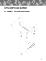
Fire Suppression System
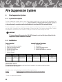
6 - 1 System Description
The fire suppression system used in your Giles Ventless Hood Fryer is an Ansul R-102 Restaurant Fire
Suppression System (Standard UL 197 Listed). Final installation, charging and testing of the system is
to be performed by an authorized Ansul distributor in accordance with the systems listing.
The fire suppression system is designed and UL listed to provide fire protection for cooking appliances
such as fryers. It protects your units, automatically 24 hours per day. The system contains piping, nozzles
(both appliance and plenum), and conduit for routing the fusible link cable through the hood.
!
WARNING
To insure adequate fire protection, DO NOT attempt to cook on this fryer without the fire
suppression system installed or serviced!
6 - 2 Installation
Factory Installed
1.
2.
3.
4.
5.
6.
7.
Installed by Ansul Distributor
Piping
Appliance and Plenum Nozzles
Tank and mounting bracket
Release Mechanism
Conduit for fusible links
Detector Brackets
Pulley & Elbows
Model No. Prot. Area
CF-200 VH
Appliance
Plenum
1.
2.
3.
4.
5.
Nozzle P/N
Quantity
Ansul P/N 56929
Ansul P/N 56929
2
2
Fusible links
Wire Rope
R-102 Suppression agent
Charging cylinder
Remote pull station (if required)
Description
Fusible Link
⁄2 N
1
⁄2 N
Globe Tech 317135
Ansul 56811
1
Temp. Rating
IMPORTANT NOTE:
The appliance and plenum nozzles have been factory installed in the proper operating position.
DO NOT MOVE OR ADJUST.
(If nozzles move during cleaning, re-set to the following locations)
Model
Nozzle Direction In Relation to the Front of the Cooking Vat
CF-200
Center of Vat
* Ansul in a registered trademark
32
135°F
165°F
Fire Suppression System
Install the fusible links listed below.
1. Fusible Link Installation, Cooking Surface
Model
CF-200 VH
Supplier
Globe
Part No.
317135
Fusible Link Rating
135°F (57°C)
1.a. The fusible link in the plenum area of the hood (in front of exhaust fan) should be Ansul part # 56811
(165°F/74°C).
Tank
A 1.5 gallon tank, Ansul part #415900 is to be used with the system.
Charging Cylinder
101 Model 20 CO2 Cartridge, Ansul part #17492
Fire Damper
The fire damper has a 285°F (141°C) fusible link.
See the illustrations to help ensure safe and proper installation of your fire suppression system. If
you have any questions concerning these procedures, contact your local representative or other
qualified service persons.
6 - 3 Remote Manual Pull Station
A remote manual pull station for the fire system may be required by local regulations in a path of exit or
egress. Ensure the pull station is clearly marked and easily accessible. Check with the authority having
jurisdiction for the requirements in your area.
6 - 4 Maintenance
The fire extinguishing system should ne maintained as outlined in the Standard for Wet Chemical
Extinguishing Systems, NFPA 17A and the instructions of the installer’s systems.
33
Fire Suppression System
6 - 5 Service
Service of the fire suppression system is to be conducted by qualified fire equipment personnel. As a minimum, field inspection of the Fire Suppression System is to be accomplished semi-annually by qualified fire
equipment service personnel. Such maintenance shall consist of the following (Consult the Giles
Enterprises Design Installation, Recharge and Maintenance Manual for complete servicing guidelines).
Semi-Annual
1. Remove charging cartridge, inspect gasket for cuts and elasticity, coat gasket with extreme temperature
grease and reinstall.
2. Remove tank, verify chemical is at proper level, clean and coat O-ring with extreme temperature grease
and reinstall.
3. Check all nozzles to insure they are free of cooking grease buildup.
4. Test the remote manual pull station for activation and wear.
5. Install test link and cut to simulate automatic actuation.
6. Clean and replace fusible links.
7. Inspect wire rope for wear at pulleys and detectors and replace if necessary.
8. Record maintenance date and maintain in a permanent file.
Annual
Same as above except the fusible links must be replaced.
12 Year
Same as above except for the following.
1. Replace R-102 fire suppression chemical.
2. Hydrostatically test the tank and cartridge.
3. Flow test the regulator
Place fire extinguishing system locking bar on fire system when servicing hood.
!
WARNING
To insure adequate fire protection, remove fire system locking bar before replacing back
and placing unit back in service!
34
Fire Suppression System
Upper Rear Panel Removed Showing Location of Fire Suppression System
Figure 12
35
Fire Suppression System
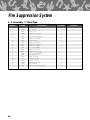
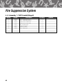
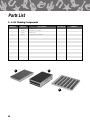
6 - 6 Assembly, 3/8" Black Pipe
Item No.
Part No.
1
2
3
4
5
6
7
8
9
10
11
12
13
14
15
16
17
18
19
20
21
22
34874
45088
46426
34888
----42050
34887
45576
44000
30929-1
40127
46701
33300
46450
46684
34886
40128
10152
25351
11275
11150
33736
36
Description
Weld Assy., 90° x 1 /2" Tubing
Tee, 3/8" Black
Nozzle, 1/2" N
Nipple, 3/8" x 47/16" Black
----Ell, 3/8" x 90° Street Black
Nipple, 3/8" x 91/8" Black
Union, 3/8" Black
Nipple, 3/8" x 4" Black
Nipple, 3/8" x 51/4" Black
Connector, 1/2" Male
Tee, 3/8" Street Black
Tubing, 11.631 x 20"
Adaptor, 3/8" Quick Seal
Ell, 3/8" x 45° Street Black
Pipe, Blk Npt 3/8" x 1
Elbow, 1/2" Union
Spacer, #6 x 0.250
Clamp, 1/2" Conduit
Washer, #8 Lock ZN
Nut, 8-2 HX ZN
Assy., Panel & Labels (Stage 4)
1
No. Req’d
1
1
4
1
7
1
2
2
1
2
2
1
2
2
1
1
1
1
1
1
1
Remarks
Fire Suppression System
6 - 6 Assembly, 3/8" Black Pipe Diagram
37
Fire Suppression System
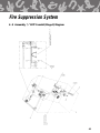
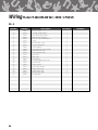
6 - 7 Assembly, 1/2" EMT Conduit (Stage 1)
Item No.
Part No.
1
2
3
4
5
6
7
46375
33184
46025
34882
34881
32195
24220
38
Description
Elbow, 90° Pulley
Conduit, 1/2" x 13/8"
Pulley, Corner/Set Screw
Conduit, 303/4" x 1/2"
Conduit, 1/2" x 1"
Conduit, 1/2" x 81/2"
Connector, 1/2" EMT
No. Req’d
1
1
3
1
1
1
1
Remarks
Fire Suppression System
6 - 7 Assembly, 1/2" EMT Conduit (Stage 1) Diagram
39
Fire Suppression System
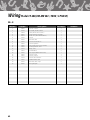
6 - 8 Assembly, 1/2" EMT Conduit (Stage 2)
Item No.
Part No.
1
2
3
4
5
6
7
8
9
10
11
12
13
14
15
16
17
40133
30227-3
------------46375
34883
40130
34884
34885
33185
40629
30227-2
31889
12300
23780
24220
40
Description
Package, Ansul Terminal Detr.
Conduit, 1/2" x 51/4"
------------Elbow, 90° Pulley
Conduit, 1/2" x 253/4"
Assy., Hood Seal Adaptor Ship
Conduit, 1/2" x 111/4"
Conduit, 1/2" x 10"
Conduit, 1/2" x 23/8"
Detector, Series
Conduit, 1/2" x 41/2"
Conduit, 1/2" x 61/2"
Washer, 1/4" Flat SAE
Bushing, Insulating Type A
Connector, 1/2" EMT
No. Req’d
1
1
8
1
4
1
1
3
1
1
1
1
1
1
Remarks
Fire Suppression System
6 - 8 Assembly, 1/2" EMT Conduit (Stage 2) Diagram
41
Fire Suppression System
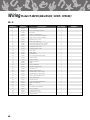
6 - 9 Assembly, 1/2" EMT Conduit (Stage 3)
Item No.
Part No.
1
2
3
4
5
6
7
8
33294
33295
11400
12050
11925
11975
25351
33296
42
Description
Assy., /2" EMT Piping (Stage 1)
Assy., 1/2" EMT Piping (Stage 2)
Screw, 10-32 x 3/8" PN HD SLT
Washer, #10 Lock Zinc Plated
Nut, 10-32 Zinc Plated
Washer, #10 Flat ZN
Clamp, 1/2" Conduit
Assy., 3/8" Black Pipe
1
No. Req’d
1
1
5
5
5
4
1
1
Remarks
(STAGE 3)
34805: ASSY., ELEC. BD., & RELEASE MECH.
MECHANISM IS ILLUSTRATED ON DRAWING
P/N 79493: INSTALLATION OF RELEASE
Fire Suppression System
6 - 9 Assembly, 1/2" EMT Conduit (Stage 3) Diagram
43
Fire Suppression System
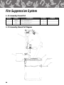
6 - 10 Assembly, Manual Pull
Item No.
Part No.
1
2
3
4
33279
34785-065
34850
20134
Description
Assy., /2" EMT Piping (Stage 1)
Conduit, 1/2" x 81/8" EMT
Assy., Cab. Bottom EMT (CF)
Cable, Wire Type 304 S/S
1
No. Req’d
Remarks
1
1
1
10
6 - 10 Assembly, Manual Pull Diagram
POINT "B"
INSTALL P/N 20134 FROM
POINTS "A" TO "B".
POINT "A"
44
Cooking Instructions
7
Cooking Instructions
7 - 1 Marinating Process
Marination is the process by which salt and special spices are absorbed into the tissue to enhance the flavor of the chicken. This procedure is one of the primary factors that accounts for Chester Fried’s remarkable taste appeal. Therefore, the marination process must be implemented and with maximum efficiency.
The Mariating Procedure:
* Draws blood from the chicken
* Tenderizes the meat
* Raises the moisture content and the weight of the bird 10 to 12%
* Allows the flavoring to be absorbed into the tissue of the met in order to enhance the flavor of the
chicken
* Helps reduce bacteria build up.
Recommended Marinating Procedure
1.
Take 3/4 cup (177ml) of Chester Fried Marinade and mix thoroughly with 3 gallons (11.4L) of cold
water.
2.
Always press the bone through the thigh and fold the wings before marinating them.
3.
Place the chicken pieces in the solution and let them soak for 12 to 18 hours at 38°F (3.3°C)
4.
Remove the chicken from the marinade water.
5.
Rinse chicken with cold tap water and place in proper storage container with colander.
6.
Place a thin layer of ice on top of the chicken and store at 38°F (3.3°C)
!
CAUTION
DO NOT allow the chicken to marinate over 18 hours.
7 - 2 Batter Dip Seasoning
The batter dip procedure is a very important bridge between marinating and breading. The batter seasoning accentuates the flavor of the meat and breading and ensures that the breading will stay on the chicken
during the frying process.
We have found most consumers appreciate a very nice crust. This batter will accomplish just that.
* Mix 3 cups (708ml) of Chester Fried Batter Dip with 3 gallons (11.4L) of COLD water.
NOTE:
When using the Chester Fried Bread and Batter Table, use 3 gallons (11.4L) of Batter Dip in the Dipper Well.
45
Cooking Instructions
!
CAUTION
Change the batter after dipping 140 lb. (63.5kg) of the poultry.
7 - 3 Breading
In some markets, the consumer demands an extra crust. This process further insulated the meat and protects the poultry from oil absorption. It also enhances the shelf life of the product if properly handled.
1.
Lightly dust the chicken in the breading mix.
2.
Place the chicken in the Batter Dip Seasoning. Totally immerse the pieces in the Batter Dip two times
coating the chicken with this solution. Allow the chicken a few seconds to drip and dump the pieces
in the breading container.
3.
Thoroughly roll the pieces in the Chester Fried Breading, coating every crevice. Then, place them on
the Staging Tray.
!
CAUTION
NEVER allow the chicken to be breaded in advance of frying. Allowing the chicken to be
pre-breaded and sit on a shelf, counter or staging tray of the batter table too far in advance
will create and unfavorable hard exterior on the finished product. Excessive time between
breading and frying the chicken allows the batter dip, which is water based to penetrate
the exterior breading creating a shell effect which ultimately produces an offensively hard
exterior.
7 - 4 Loading the Chicken
The weight of the chicken will determine the quantity the cooker can accept and the specific cook time. If
each bird weighs 2 3/4 lb. (1.2k). (See chart for product amount) For alternative weights consult your
Chester Fried Representative.
Piece
Thighs
Legs
Breast
Wings
Total
CF-200
5
5
5
5
20
Dark meat has a higher moisture content than white meat. To guarantee proper cooking, load the dark
meat ahead of the white meat. Dark meat is the Thigh (large) and the Leg (small). White meat is the
Breast (large), and Wing (small). Place the chicken in the basket in this order: large dark pieces, small
dark pieces, large white pieces, small white pieces.
Loading Sequence:
46
Cooking Instructions
1. Thighs
2. Legs
3. Breast
4. Wings
NOTE: Cook Time: 13 minutes
Cook Temp: 335°F (168°C)
7 - 5 Using IQF Chicken and Pre-Marinated Chicken
Good results can be obtained using a marinated IQF or a “pre-marinated” chicken product rather than
fresh chicken. Use of a pre-marinated product eliminates the need for marinating at the store level. The
IQF product should be thawed and processed in the same fashion as fresh chicken.
7 - 6 Stirring the Chicken
In order to protect the exterior coating desired by your customer, your fryer is equipped with a stir message and a repeating one second on/one second off sound alarm telling you oil’s time to stir your product.
This time is a Chester Fried preset time of 62% of each of the 8 menu times to prevent sticking. When
this time occurs:
1.
Remove the Lid.
2.
Take the Stirrer and gently, stir the chicken and then silence the alarm by pressing the lighted menu
key once.
7 - 7 Preparing the Potatoes
The recommended fresh potato is a white Idaho potato ranging from a 80 count in size. The Idaho potato
comes out of the fry-kettle as light and golden in color as your fried chicken. It has a longer shelf life and
holds its color better in the Warmer than other potatoes, such as the Russet.
However, there are many different potatoes available on the market; and, local testing is the only sure way
to satisfy your customers.
Potato Wedges
1.
Scrub the potato and run it through the Slicer. We have found the potato is in its most desirable state
for frying when cut into an eight piece wedge. Some have attempted to cut the potato into a four
piece wedge but our research has shown the eight-piece cut to be more desirable in texture and
flavor.
2.
Drop the wedges into a fresh marinating solution.
47
Cooking Instructions
!
CAUTION
DO NOT marinate the chicken and potatoes in the same container. DO NOT use the same
marinade solution more than once. The potatoes need to soak 12 to 18 hours in the
solution to give it that Chester Fried flavor.
3.
Remove the potato wedges from the marinade water.
4.
Lightly Dust the potato wedges in the Breading Mix.
5.
Place the wedges in the Batter Dip Seasoning Mix. Totally immerse them in the Batter Dip two times.
6.
Thoroughly coat the wedges with the Breading a second time and place on Staging Tray.
7.
Place them in the fryer for 8 minutes at 335°F (168°C).
!
CAUTION
After marinating potatoes, add fresh water to potatoes until ready for use.
48
Troubleshooting
8 - 1 Temperature Control System with Cooking Computer
Problem
FRYER WILL NOT TURN ON:
No power light
Probable Cause
A. Not connected to power source.
B. Bad fuse or circuit breaker.
C. Fuse holder cracked.
D. Power Switch bad.
E. Improper supply voltage.
F. Hood Cover not closed.
G. Fire system not armed.
H. “HOLD to START” Button not
held for 5 seconds.
Repair Procedure
A. Connect to proper power
source.
B. Check fuse or breaker.
C. Replace fuse holder.
D. Replace Power Switch.
E. Connect to proper voltage source.
F Close Hood cover.
G. Call Ansul Distributor.
H. Hold button for 5 seconds.
FRYER WILL NOT HEAT:
Power light on. Heat light not on.
A. Selector Switch not in cook
position.
A. Place selector to switch in cook
position.
FRYER WILL NOT HEAT:
Power light on. Selector Switch
in cook position. Heat light not on.
A. Set pot set below desired
temperature.
B. Drain Valve open.
C. Variable probe shorted or open.
D. Loose wire.
E. Contactor failure.
F. Element bad.
G. Selector Switch bad.
A. Set temperature controller to
to desired temperature.
B. Close Drain Valve.
C. Replace probe.
D. Repair loose wire.
E. Replace faulty contactor.
F. Replace element.
G. Replace Selector Switch.
FRYER WILL NOT HEAT:
Power light on. Selector Switch in
cook position. High Limit light On.
A. Power surge.
B. Plug not completely in.
C. Oil level too low.
D. Sticking contactor.
E. Bad high limit board.
F. High limit probe short or open.
G. Line spikes or noise.
A. Turn Power Switch off for 5 sec.
B. Reconnect to power source.
C. Fill to kettle oil level mark.
D. Replace contactor.
E. Replace high limit board.
F. Replace High limit probe.
G. Filter line or remove noise
source.
FRYER HEATS SLOW:
(slow recovery) Heat light stays on.
A. Incorrect cooking procedures.
A. Consult operations manual for
proper cooking procedure.
B. Replace bad element.
C. Replace contactor.
D. Repair loose wire.
E. Supply proper voltage.
B. Element failing.
C. Contactor failing.
D. Loose wire.
E. Low supply voltage.
49
Troubleshooting
8 - 1 Temperature Control System with Cooking Computer
Problem
Probable Cause
Repair Procedure
FRYER HEATS SLOW:
(short cycling) Heat light off and
on continuously.
A. Low supply voltage.
B. Variable probe touching element.
A. Supply proper voltage.
B. Reposition variable probe.
OIL TEMPERATURE ERRATIC:
A. Probe bad.
B. Contactor failing.
C. Temperature controller faulty.
D. Loose wire.
A. Replace probe.
B. Replace contactor.
C. Replace temperature controller.
D. Repair loose wire.
OIL SMOKING:
A. Old oil.
B. Over temperature.
A. Change oil.
B. Check temperature control
system.
C. Clean elements.
D. Replace element.
E. Supply proper voltage.
F. Keep oil at oil level line.
C. Dirty element.
D. Element failure.
E. Improper element voltage.
F. Low oil level.
50
Troubleshooting
8 - 2 Automatic Basket Lift and Oil Filtration System
Problem
BASKET WILL NOT GO UP OR
DOWN: Elevator motor not on.
Probable Cause
Repair Procedure
A. Power not on.
B. Selector Switch not in cook
position.
C. Timer faulty.
D. Elevator micro switch out of
adjustment.
E. Elevator micro switch bad.
A. Turn Power Switch to on position.
B. Place Selector Switch in cook
position.
C. Replace faulty Timer.
D. Adjust micro switch.
BASKET WILL NOT GO UP OR
DOWN:
A. Basket over loaded.
B. Elevator binding (slide bar dirty).
C. Elevator motor gear box faulty.
D. Drive sprocket set screw loose.
E. Over tension on slide bar.
A. Put less product in basket.
B. Clean slide bars.
C. Replace elevator motor.
D. Tighten drive sprocket set screw.
E. Adjust slide bar tension.
BASKET GOES UP AND DOWN
A. Master link tab bent or broken.
B. Micro switch out of adjustment.
C. Improper tension on Slide bar.
A. Replace master link.
B. Adjust micro switch.
C. Adjust slide bar tension.
OIL NOT RETURNING TO VAT:
A. COOK/FILTER Switch not in
“FILTER” position.
B. Air leak (hose, fittings, filter paper).
C. Bad pump motor capacitor.
D. Pump motor is bad.
E. Oil pump sticking.
A. Place Selector Switch in filter
position.
B. Repair air leak.
C. Replace pump motor capacitor.
D. Replace pump motor.
E. Free stuck pump.
OIL PUMP STICKING:
A. Boil out being run through pump.
B. Old oil allowed to sit in pump.
C. Solid shortening allowed to sit
in pump.
A. Disassemble and re-oil pump.
B. Run clean oil through pump.
C. Disassemble and re-oil pump and
clean out plumbing.
E. Replace micro switch.
51
Parts
9
Parts
Models CF-200 and CF-200 VH
Front Control Panel
Rear View of Lower Cabinet
Rear View of Header Section
Rear View of Upper Hood Section
Filter Pan Assembly
Air Cleaning Components
52
Parts List
9 - 1 Front Control Panel
Item No.
Part No.
1
2
3
4
5
6
7
8
23275
23225
24241
24209
22275
23225
22875
22300
5
Description
No. Req’d
Power Switch
Selector Switch
Cooking Timer
On/Check/Wash Light
Power/Heat/Hi-Limit Indicator Light
Up/Down Switch
Potentiometer
Filter Missing Light
1
7
6
Remarks
1
1
1
1
1
1
1
1
3
2
4
8
53
Parts List
9 - 2 Rear View of Lower Cabinet
Item No.
Part No.
1
2
3
4
32158
23175
78539
30028-8
Description
No. Req’d
Elevcator Motor
Micro Switch
Filter Pan (Complete Assemble) CF-200
Micro Switch Bracket
Remarks
1
1
1
1
4
2
1
3
54
Parts List
9 - 3 Rear View of Header Section
Item No.
Part No.
1
*
2
3
4
4
5
5
6
6
21950
21900
23754
23751
21191
21174
22363
21425
24000
24001
Description
No. Req’d
Remarks
Fuse Holder
Fuse, SC-15, 15 AMP Fuse
Safety Board 425° (218.12°C)
Terminal Block
Relay208V
Relay240V
Heating Element 208V
Heating Element 240 V
Variable Control Board 240 V
Variable Control Board 208 V
* Not Shown
6
3
1
1
5
2
4
55
Parts List
9 - 4 Rear View of Upper Hood Section
Item No.
Part No.
1
2
3
4
5
6
7
8
9
10
11
22361
24237
23001
23571
23782
22950
20002
23776
24208
40129
Description
No. Req’d
Remarks
Fan
Switch, Plunger (Not Shown)
Vacuum Switch
Terminal Block
Sonalert Clogged Filter
Sonalert
LED Driver (Part of HV Supply)
Switch Ass‘y Fire Ext. Actuator
Air Filter Module
HV Power Supply
Ansul Tank Ass‘y W/Adapter (Wet)
5
1
6
10
9
11
3
8
56
Parts List
9 - 5 Filter Pan Assembly
Item No.
Part No.
1
2
3
4
5
6
7
8
9
70314
44150
42250
30938
54526
30040-4
30039-8
30932
40608
Description
No. Req’d
Remarks
Hose Assembly
/2" (1.27cm) Brass Assembly Q D male
90° (32.2°C) 1/2" (1.27cm) Street Ell
Hold Down Frame
Hold Down Lever
Hold Down Frame Stud
Filter Pan Stud
Filter Pan Only
Filter Pan Screen
1
1
2
3
3
7
9
4
5
6
8
57
Parts List
9 - 6 Air Cleaning Components
Item No.
Part No.
1
2
3
3
31137
22360
45076
45077
1
Description
No. Req’d
Charcoal Filter
Electronic Air Cleaner
Baffle Filter
Baffle Filter (for Canada)
2
3
58
Remarks
Wiring Model CF-200 / CF-200 VH
10
Wiring Diagrams
Wiring Diagram Model CF-200 (1 Phase)
Wiring Diagram Model CF-200 VH 208/240 VAC (1 Phase)
Wiring Diagram Model CF-200 VH 220/380 VAC (1 Phase)
59
Wiring Model CF-200 (208-240 VAC / 60 HZ / 1 PHASE)
10 - 1
Item No.
Part No.
1
2
3
4
5
6
7
8
9
10
11
11
12
12
13
14
15
16
17
18
18
19
20
22875
32158
23754
76925
30967
21152
25275
23175
23225
21950
21425
22363
21174
21191
23751
22275
23275
23225
21157
24000
24001
25225
30981
60
Description
Set Pot, 0-350°F
Assembly, Elevator Motor
Safety Board, 425°F (218°C)
Pump & Motor Assembly
Timer, Ass‘y Mechanical (DIEHL)
Sensor
Wire Nut, Blue, Small
Switch, Elevator Micro
Switch Up/Down
Fuse Holder w/15 A Fuse (21900)
Heating Element, 240V
Heating Element, 208V
Relay, 240V
Relay, 208V
Terminal Block
Pilot Light (PWR/Heat/ Hi-Limit)
Switch, Power
Switch, Selector
Switch, Valve Interlock
Variable Board, 240V
Variable Board, 208V
Wire Nut, Blue, Large
Wiring Diagram
No. Req’d
1
1
1
1
1
2
3
1
1
2
1
1
2
2
2
1
1
1
1
1
1
2
1
Remarks
Wiring Model CF-200 (208-240 VAC / 60 HZ / 1 PHASE)
NOTE: UNLESS OTHERWISE NOTED
ALL WIRES ARE 18 GAUGE.
10 - 2 Wiring Diagram
61
Wiring Model CF-200 (220-380 VAC / 50 HZ / 1 PHASE)
10 - 3
Item No.
Part No.
1
2
3
4
5
6
7
8
9
10
11
12
13
14
15
16
17
18
19
20
22875
32158
23754
76925
30967
21152
25275
23175
23225
21950
21425
21174
23751
22275
23275
23225
21157
24000
25225
30981
62
Description
Set Pot, 0-350°F
Assembly, Elevator Motor
Safety Board, 425°F (218°C)
Pump & Motor Assembly
Timer, Ass‘y Mechanical (DIEHL)
Sensor
Wire Nut, Blue
Switch, Elevator Micro
Switch Up/Down
Fuse Holder w/15 A Fuse (21900)
Heating Element, 240V
Relay, 240V
Terminal Block
Pilot Light (PWR/Heat/ Hi-Limit)
Switch, Power
Switch, Selector
Switch, Valve Interlock
Variable Board, 240V
Wire Nut, Blue, Large
Wiring Diagram
No. Req’d
1
1
1
1
1
2
3
1
1
2
1
2
2
1
1
1
1
1
2
1
Remarks
Wiring Model CF-200 (220-380 VAC / 50 HZ / 1 PHASE)
NOTE: UNLESS OTHERWISE NOTED
ALL WIRES ARE 18 GAUGE.
10 - 4 Wiring Diagram
63
Wiring Model CF-200 VH (208-240 VAC / 60 HZ / 1 PHASE)
10 - 5
Item No.
Part No.
1
2
3
4
5
6
7
8
9
10
11
11
12
12
13
14
15
16
17
18
19
20
21
22
23
23
24
25
26
27
28
29
30
31
32
33
34
21125
24208
22361
23200
30967
21152
25275
24237
20002
21950
21425
22363
21174
21191
23751
22275
23275
23225
23776
76925
23225
23782
22950
21157
24000
24001
23175
23754
23001
31139
22300
24209
32158
22875
20298
25225
31143
64
Description
Contact Board
Power Pack w/Driver Board
Fan Motor
Switch, Hood Interlock
Timer Ass’y Mechanical (DIEHL)
Temp Sensor: Safety & Variable
Wire Nut, Blue, Small
Switch, Filter Missing
Switch Assembly, Fire Ext. Actuator
Fuse Holder w/15A Fuse (21900)
Heating Element, 240V
Heating Element, 208V
Relay, 240V
Relay, 208V
Terminal Block
Pilot Light (Pwr/Heat/Hi-Limit)
Swtich, Power
Switch, Selector
Module, Air Filter
Pump
Switch, Up/Down
Sonalert, Clogged Filter
Sonalert, E.A.C.
Switch, Valve Interlock
Variable Board, 0-350° (240V)
Variable Board, 0-350° (208V)
Switch, Micro Elevator Ass’y
Safety Board, 425°
Vacuum Switch
Switch Assembly, Baffle Filter
Light, Filter Missing
LED
Assembly, Elevator Motor
Set Pot, 0-350°F
Copper Braid Shield
Wire Nut, Blue, Large
Wiring Diagram
No. Req’d
1
1
1
1
1
2
7
1
1
2
1
1
2
2
3
1
1
1
1
1
1
1
1
1
1
1
1
1
1
1
1
1
1
1
1
2
1
Remarks
Wiring Model CF-200 VH (208-240 VAC / 60 HZ / 1 PHASE)
NOTE: UNLESS OTHERWISE NOTED
ALL WIRES ARE 18 GAUGE.
10 - 6 Wiring Diagram
65
Wiring Model CF-200 VH (220-380 VAC / 50 HZ / 1 PHASE)
10 - 7
Item No.
Part No.
1
2
3
4
5
6
7
8
9
10
11
12
12
13
14
15
16
17
18
19
20
21
22
23
24
25
26
27
28
29
30
31
32
33
34
21125
24208
22361
23200
30967
21152
25275
24237
20002
21950
21425
21174
21191
23751
22275
23275
23225
23776
76925
23225
23782
22950
21157
24000
23175
23754
23001
31139
22300
24209
32158
22875
20298
25225
31143
66
Description
Contact Board
Power Pack w/Driver Board
Fan Motor
Switch, Hood Interlock
Timer, Mechanical (DIEHL)
Sensor
Wire Nut
Switch, Filter Missing
Switch Assembly, Fire Ext. Actuator
Fuser Hldr w/15A Fuse (21900)
Heating Element, 240V
Relay, 240V
Relay, 208V
Terminal Block
Pilot Light (Pwr/Heat/Hi-Limit)
Swtich, Power
Switch, Selector
Module, Air Filter
Pump
Switch, Up/Down
Sonalert, Clogged Filter
Sonalert, E.A.C.
Switch, Valve Interlock
Variable Board, 0-350° (240V)
Switch, Micro Elevator Ass’y
Safety Board, 425°
Vacuum Switch
Switch Assembly, Baffle Filter
Light, Filter Missing
LED
Assembly, Elevator Motor
Set Pot, 0-350°F
Copper Braid Shield
Wire Nut, Blue, Large
Wiring Diagram
No. Req’d
1
1
1
1
1
2
7
1
1
2
1
2
2
3
1
1
1
1
1
1
1
1
1
1
1
1
1
1
1
1
1
1
1
2
1
Remarks
Wiring Model CF-200 VH (220-380 VAC / 50 HZ / 1 PHASE)
NOTE: UNLESS OTHERWISE NOTED
ALL WIRES ARE 18 GAUGE.
10 - 8 Wiring Diagram
67