1
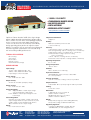
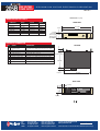
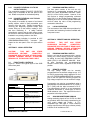
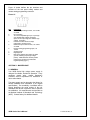
R Instruction Manual 205B SERIES Rack-Mount High Voltage Power Supply SPELLMAN HIGH VOLTAGE ELECTRONICS CORPORATION One Commerce Park Valhalla, New York, 10595 +1(914) 686-3600 * FAX: +1(914) 686-2870 E-mail: [email protected] Website: http://www.spellmanhv.com 205B Series User’s Manual 118123-001 Rev A 205B HIGH VOLTAGE POWER SUPPLY S P E L L M A N H I G H V O LTA G E E L E C T R O N I C S C O R P O R AT I O N PAGE 1 OF 2 • 1-50KV @ 15-30 WATTS • STANDARD RACK MOUNTED DESIGN • LOW RIPPLE AND NOISE • DIGITAL METERING • REVERSIBLE OUTPUT POLARITY www.spellmanhv.com/manuals/205B Spellman’s Bertan brand of 205B Series high voltage power supplies provide regulated high voltage outputs from 1 to 50kV. The low noise, linear topology employed results in extremely low output ripple specifications. These 15 to 30 watt units are inherently reversible by design, providing either positive or negative output polarity. The 205B is fully arc and short circuit protected. Excellent regulation specifications are featured along with outstanding stability performance. TYPICAL APPLICATIONS HiPot Testing CRT Testing Electrostatics E Beam Systems General Laboratory Usage Temperature Coefficient: ≤50ppm/°C Stability: ≤0.01%/hour, 0.02% per 8 hours after a 1/2 hour warm up Accuracy: Current Monitor: ±(0.5% of reading + 0.25% of maximum) Remote Programming: ±(0.1% of setting + 0.1% of maximum) Voltage Monitor: ±(0.1% of reading + 0.1% of maximum) Front Panel Meter: Voltage ±(0.1% of setting + 0.1% of maximum) Current: ±(0.25% of setting + 0.25% of maximum) Front Panel Control: ±(0.25% of setting + 0.05% of maximum) Operating Temperature: 0°C to +50°C Storage Temperature: -40°C to +85°C SPECIFICATIONS Input Voltage: 115Vac, ±10%, 50/60 Hertz @ 1 amp 230Vac, ±10%, 50/60 Hertz @ 0.5 amps Input voltage is switch selectable Humidity: 20% to 85%RH, non-condensing Input Line Connector: IEC320 EMI filter/ input connecter, a detachable line cord is provided Output Voltage: See “model selection” table Interface Connector: 9 pin “D” connector, a mating connector is provided Output Polarity: All units are reversible polarity by design Output Connector: A detachable 10 foot (3 meter) long HV cable is provided Output Current: See “model selection” table Cooling: Convection cooled Voltage Regulation: Line: ≤50ppm/0.001% of rated output voltage over specified input voltage range Load: ≤0.005% of rated output voltage for a full load change Current Regulation: Internally set to limit at 105% of rated current at full output voltage. Maximum output current at any other voltage setting must be derated linearly down to 30% of maximum at zero output voltage. Ripple: See “model selection” table USA UK JAPAN CHINA +1-631-630-3000 +44 (0)1798 877000 +81 (0)48-447-6500 +86 (0)512-67630010 Dimensions: 1-20kV:19.0˝ W X 3.5˝ H X 9.625˝ D (483mm X 89mm X 244mm) 30-50kV:19.0˝ W X 5.25˝ H X 16.0˝ D (483mm X 133mm X 406mm) Weight: ≤20 pounds (9.1kg) up to and including 20kV units, ≤35 pounds (15.9kg) for 30kV and 50kV units Regulatory Approvals: Compliant to 2004/108/EC, the EMC Directive and 2006/95/EC, the Low Voltage Directive. FAX: +1-631-435-1620 FAX: +44 (0)1798 872479 FAX: +81 (0)48-447-6501 FAX: +86 (0)512-67630030 e-mail: [email protected] www.spellmanhv.com 128046-001 REV.F Spellman High Voltage is an ISO 9001:2000 and ISO 14001:2004 registered company 205B HIGH VOLTAGE POWER SUPPLY S P E L L M A N H I G H V O LTA G E E L E C T R O N I C S C O R P O R AT I O N PAGE 2 OF 2 DIMENSIONS: in.[mm] MODEL SELECTION TABLE 205B Series 205B-01R 205B-03R 205B-05R 205B-10R 205B-20R 205B-30R 205B-50R Voltage 0 to 1kV 0 to 3kV 0 to 5kV 0 to 10kV 0 to 20kV 0 to 30kV 0 to 50kV Current 0 to 30mA 0 to 10mA 0 to 5mA 0 to 2.5mA 0 to 1mA 0 to 0.5mA 0 to 0.3mA Ripple 10mV 30mV 50mV 100mV 300mV 400mV 2 volts FRONT VIEW 19.00 [483] .25 [6.3] 18.33 [465] .34 [8.6] 3.50 [89] UP TO 20kV, BUT 5.25 [133] 3.00 [76] ON 30kV AND 50kV MODELS POWER HIGH VOLTAGE INTERFACE CONNECTOR PIN 1 2 3 4 5 6 7 8 9 TOP VIEW SIGNAL PARAMETERS Voltage Monitor n/c Enable +5Vdc Reference Current Monitor Voltage Program Input Analog Ground Digital Ground Polarity Indicator 0 to 5Vdc = 0 to 100% rated voltage, Zout = 10KΩ none TTL “0” disables HV, TTL “1” or open enables HV +5.0Vdc @ 10mA, maximum 0 to 5Vdc = 0 to 100% rated current, Zout = 10KΩ 0 to 5Vdc = 0 to 100% rated voltage, Zin = 1MΩ Ground Ground (for use only with 200-C488, sold separately) Open collector, 30V @ 25mA, positive = ON 1.62 [41] .12 [3] 9.63 [244] 1.00 [25.4] 16.75 [425] BACK VIEW 1.12 [28.4] HV .19 [4.8] REMOTE 3.12 [79.2] USA UK JAPAN CHINA +1-631-630-3000 +44 (0)1798 877000 +81 (0)48-447-6500 +86 (0)512-67630010 FAX: +1-631-435-1620 FAX: +44 (0)1798 872479 FAX: +81 (0)48-447-6501 FAX: +86 (0)512-67630030 e-mail: [email protected] www.spellmanhv.com 128046-001 REV.F Spellman High Voltage is an ISO 9001:2000 and ISO 14001:2004 registered company IMPORTANT SAFETY PRECAUTIONS SAFETY THIS POWER SUPPLY GENERATES VOLTAGES THAT ARE DANGEROUS AND MAY BE FATAL. OBSERVE EXTREME CAUTION WHEN WORKING WITH THIS EQUIPMENT. High voltage power supplies must always be grounded. Do not touch connections unless the equipment is off and the Capacitance of both the load and power supply is discharged. Allow five minutes for discharge of internal capacitance of the power supply. Do not ground yourself or work under wet or damp conditions. SERVICING SAFETY . Maintenance may require removing the instrument cover with the power on. Servicing should be done by qualified personnel aware of the electrical hazards. WARNING note in the text call attention to hazards in operation of these units that could lead to possible injury or death. CAUTION notes in the text indicate procedures to be followed to avoid possible damage to equipment. Copyright 2000, Spellman High Voltage Electronics Corporation. All Rights Reserved. This information contained in this publication is derived in part from proprietary and patent data. This information has been prepared for the express purpose of assisting operating and maintenance personnel in the efficient use of the model described herein, and publication of this information does not convey any right to reproduce it or to use it for any purpose other than in connection with installation, operation, and maintenance of the equipment described. 118004-001 REV. B WICHTIGE SICHERHEITSHINWEISE SICHERHEIT DIESES HOCHSPANNUNGSNETZTEIL ERZEUGT LEBENSGEFÄHRLICHE HOCHSPANNUNG. SEIN SIE SEHR VORSICHTIG BEI DER ARBEIT MIT DIESEM GERÄT. Das Hochspannungsnetzteil muß immer geerdet sein. Berühren Sie die Stecker des Netzteiles nur, wenn das Gerät ausgeschaltet ist und die elektrischen Kapazitäten des Netzteiles und der angeschlossenen Last entladen sind. Die internen Kapazitäten des Hochspannungsnetzteiles benötigen ca. 5 Minuten, um sich zu entladen. Erden Sie sich nicht, und arbeiten Sie nicht in feuchter oder nasser Umgebung. SERVICESICHERHEIT Notwendige Reparaturen können es erforderlich machen, den Gehäusedeckel während des Betriebes zu entfernen. Reparaturen dürfen nur von qualifiziertem, eingewiesenem Personal ausgeführt werden. “WARNING” im folgenden Text weist auf gefährliche Operationen hin, die zu Verletzungen oder zum Tod führen können. “CAUTION” im folgenden Text weist auf Prozeduren hin, die genauestens befolgt werden müssen, um eventuelle Beschädigungen des Gerätes zu vermeiden. 118004-001 REV. B PRECAUTIONS IMPORTANTES POUR VOTRE SECURITE CONSIGNES DE SÉCURITÉ CETTE ALIMENTATION GÉNÈRE DES TENSIONS QUI SONT DANGEUREUSES ET PEUVENT ÊTRE FATALES. SOYEZ EXTRÊMENT VIGILANTS LORSQUE VOUS UTILISEZ CET ÉQUIPEMENT. Les alimentations haute tension doivent toujours être mises à la masse. Ne touchez pas les connectiques sans que l’équipement soit éteint et que la capacité à la fois de la charge et de l’alimentation soient déchargées. Prévoyez 5 minutes pour la décharge de la capacité interne de l’alimentation. Ne vous mettez pas à la masse, ou ne travaillez pas sous conditions mouillées ou humides. CONSIGNES DE SÉCURITÉ EN CAS DE REPARATION La maintenance peut nécessiter l’enlèvement du couvercle lorsque l’alimentation est encore allumée. Les réparations doivent être effectuées par une personne qualifiée et connaissant les risques électriques. Dans le manuel, les notes marquées « WARNING » attire l’attention sur les risques lors de la manipulation de ces équipements, qui peuvent entrainer de possibles blessures voire la mort. Dans le manuel, les notes marquées « CAUTION » indiquent les procédures qui doivent être suivies afin d’éviter d’éventuels dommages sur l’équipement. 118004-001 REV. B IMPORTANTI PRECAUZIONI DI SICUREZZA SICUREZZA QUESTO ALIMENTATORE GENERA TENSIONI CHE SONO PERICOLOSE E POTREBBERO ESSERE MORTALI. PONI ESTREMA CAUTELA QUANDO OPERI CON QUESO APPARECCHIO. Gli alimentatori ad alta tensione devono sempre essere collegati ad un impianto di terra. Non toccare le connessioni a meno che l’apparecchio sia stato spento e la capacità interna del carico e dell’alimentatore stesso siano scariche. Attendere cinque minuti per permettere la scarica della capacità interna dell’alimentatore ad alta tensione. Non mettere a terra il proprio corpo oppure operare in ambienti bagnati o saturi d’umidità. SICUREZZA NELLA MANUTENZIONE. Manutenzione potrebbe essere richiesta, rimuovendo la copertura con apparecchio acceso. La manutenzione deve essere svolta da personale qualificato, coscio dei rischi elettrici. Attenzione alle AVVERTENZE contenute nel manuale, che richiamano all’attenzione ai rischi quando si opera con tali unità e che potrebbero causare possibili ferite o morte. Le note di CAUTELA contenute nel manuale, indicano le procedure da seguire per evitare possibili danni all’apparecchio. 118004-001 REV. B TABLE OF CONTENTS I. INTRODUCTION 1.0 Scope of Manual…………………………………………………………. 2 1.1 Purpose of Equipment……………………………………………………. 2 1.2 Description………….……………………………………………………. 2 II. OPERATION 2.1 Installation………….……………………………………………………. 2.2 Input Power………….………………………………………………...…. 2.3 Voltage Control….………….…………………………………………. 2.4 Polarity Reversal……….…………………………………………………. 2.4.1 Polarity Reversal – 1kV to 5kV Output Models………….. 2.4.2 Polarity Reversal – 10kV to 50kV Output Models………… III. 2 2 2 2 3 3 LOCAL OPERATION 3.1 Front Panel Controls.………………………………………………… 3 3.2 Program Control Switch…………………………………………………… 3 3.3 Local Operation……………………………………………………………. 3 IV. REMOTE ANALOG OPERATION 4.1 Program Control Switch…………………………………………………. 3 4.2 Remote Control………………………………………………………….. 3 4.3 Analog Monitoring Signals.………………………………………….. 3/4 V. MAINTENANCE 5.1 General…………………………………………………………………. 205B Series User’s Manual 1 4 118124-001-Rev. A THIS UNIT CONTROLS HAZARDOUS VOLTAGES. DO NOT APPLY INPUT POWER UNLESS ADEQUATE GROUNDING IS PROVIDED TO THE POWER SUPPLY AND THE HIGH VOLTAGE OUTPUT HAS BEEN PROPERLY CONNECTED. THE DATA CONTAINED IN THIS MANUAL IS SUBJECT TO CHANGE WITHOUT NOTICE. WRITTEN PERMISSION FROM SPELLMAN HIGH VOLTAGE IS REQUIRED PRIOR TO THE REPRODUCTION OF ANY TECHNICAL DATA CONTAINED IN THIS MANUAL. SECTION I: GENERAL DESCRIPTION 1.0 SCOPE OF MANUAL This manual is provided to assist the user in the installation and operation of the Spellman Series 205B rack-mountable high voltage power supplies. Statements apply to all models in the Series unless reference is made to specific models. For the protection of personnel and equipment, it is essential that this manual be thoroughly read prior to the installation and application of power. 1.1 PURPOSE OF EQUIPMENT The series 205B is a family of regulated precision regulated, locally and remotely variable high voltage power supplies. They offer exceptional performance in such critical applications as nuclear and electro-optical instrumentation, medical imaging and capillary zone electrophoresis and precision CRT displays. 1.2 DESCRIPTION The units are fully enclosed and designed to mount in a standard 19” rack. A wide range of stable output voltages from 1kV up to 50 kV is available. The output voltage is set either by front panel controls or remote analog voltage or resistance programming. Remote analog monitoring is provided on all models. Output polarity reversal is achieved by turning a polarity switch on the rear panel of 1kV, 3kV and 5kV models. The 10kV and higher output models have an internal polarity reversing assembly that is easily accessible in the field. NOTE: in either case, polarity reversal MUST ONLY BE DONE WHEN THE HIGH VOLTAGE IS OFF. The Series 205B units contain a DC power supply that converts the AC line power to a low voltage DC and a DC-to-DC converter that generates the high DC voltage. Low voltage electronics solid-state analog circuits are placed on plug–in printed circuit 205B Series User’s Manual 2 boards. The high voltage assembly is fully encapsulated in silicone rubber for reliable, arcfree, stable operation. SECTION II: OPERATION CAUTION! THIS UNIT CAN STORE HAZARDOUS VOLTAGE. COMPLETELY DISCHARGE HIGH VOLTAGE AT REAR PANEL GROUND TERMINAL BEFORE ATTEMPTING REMOVAL OF THE HIGH VOLTAGE CABLE 2.1 INSTALLATION: The 205B Series high voltage power supplies mount in a standard 19” rack. 2.2 INPUT POWER The input AC line voltage required is 115V/230VAC, ±10%, 50-400Hz, single phase. The LINE VOLTAGE selector switch on the rear panel MUST BE SET for either 115VAC or 230VAC BEFORE application of input power. 2.3 VOLTAGE CONTROL The 205B Series power supply has two modes of controlling the high voltage outputs available to the user. Set the PROGRAM CONTROL switch (S101) on the rear panel to LOCAL for front panel control. For remote analog control, set the switch to the REMOTE ANALOG position. The high voltage output can then be remotely programmed either from an external voltage source or by using an external potentiometer. When S101 is in the REMOTE ANALOG position, the front panel controls will have no effect on the output voltage setting. At all times, regardless of the position of the rear panel PROGRAM CONTROL switch, the user may enable or disable the high voltage output by switching the HV ENABLE switch on the front panel. In addition, the voltage and current monitors are always active. Thus, even when the PROGRAM CONTROL switch is set to REMOTE ANALOG control position, the front panel and the remote analog monitors continue to make voltage and current readings available. 2.4 POLARITY REVERSAL The front panel LED display will indicate which polarity the unit is set for. The display illuminates even if there is no high voltage output. CAUTION – LINE INPUT POWER MUST BE TURNED OFF AND THE HIGH VOLTAGE SHOULD BE DISCHARGED FULLY BEFORE PROCEEDING TO REVERSE THE POLARITY. 118124-001-Rev.A 2.4.1 POLARITY REVERSAL 1kV TO 5kV OUTPUT MODELS The screwdriver-rotatable POLARITY SELECTOR switch (S3) is accessible at the rear panel of the unit. Rotate as required for the desired polarity. 2.4.2 POLARITY REVERSAL 10kV TO 50kV OUTPUT MODELS The polarity is reversible by means of an internal polarity module, which is easily accessible upon removal of the top cover. Polarity is reversed by removing two diagonally opposed Philips head screws, lifting up on the module, rotating it 180°, and then reinserting it. A safety interlock automatically ensures that the high voltage cannot be turned on unless this module is fully seated and installed in one polarity position or the other. A remote polarity indication is provided at J107 (PROGRAMMING/MONITOR) connector jack located on the rear panel of the unit (see section 4.3). SECTION III: LOCAL OPERATION CAUTION! THIS UNIT CAN STORE HAZARDOUS VOLTAGE. COMPLETELY DISCHARGE HIGH VOLTAGE AT REAR PANEL GROUND TERMINAL BEFORE ATTEMPTING REMOVAL OF THE HIGH VOLTAGE CABLE 3.1 FRONT PANEL CONTROLS Figure 4.1 below is the typical layout of the 205B Series front panel Figure 3.1 SWITCHES/PUSH BUTTONS/ INDICATORS/DIALS POWER ON-OFF kV/mA SWITCH VOLTS 3.2 PROGRAM CONTROL SWITCH The front panel controls of the unit are only functional for programming purposes when the units’ rear panel PROGRAM CONTROL switch (S101) is in the LOCAL position. However, if the unit receives a voltage programming command while S101 is in the Remote Analog position, the switching of S101 to its LOCAL position afterwards will then cause the value of that programming command to take effect. 3.3 LOCAL OPERATION The local mode of the 205B Series provides all of the control and monitoring functions available with front panel control. SECTION IV: REMOTE ANALOG OPERATION CAUTION! THIS UNIT CAN STORE HAZARDOUS VOLTAGE. COMPLETELY DISCHARGE HIGH VOLTAGE AT REAR PANEL GROUND TERMINAL BEFORE ATTEMPTING REMOVAL OF THE HIGH VOLTAGE CABLE 4.1 PROGRAM CONTROL SWITCH Before a unit can be programmed with a remote analog (0 to +5VDC) signal, it must be configured by setting its rear panel PROGRAM CONTROL switch (S101) in the REMOTE ANALOG. Note: All other monitoring and non-programming functions remain active, regardless of the S102 position. 4.2 REMOTE CONTROL The high voltage output can be remotely programmed from an external voltage source. A 0 to +5VDC programming voltage applied to Pin 6 of the J107 (PROGRAMMING/MONITOR) connector jack on the rear panel will remotely program the high voltage output from zero to maximum voltage. FUNCTION/PURPOSE Enables and disables AC power Controls the output parameter that the front panel display exhibits Illuminated when the meter is displaying the output current mA Illuminated when the meter is displaying the output current HIGH VOLTAGE CONTROL Adjusts the high voltage output 205B Series User’s Manual 3 Programming can also be accomplished using a potentiometer connected between Pin 4 (+5VDC), Pin 7 (GND) with the wiper connected to Pin 6. The potentiometer should be a low temperature coefficient wirewound or cermet type of 5kȍ to 20kȍ resistance value. The output will then be in proportion to the wiper position. 4.3 ANALOG MONITORING SIGNALS Analog monitoring signals of 0 to +5VDC via 10kȍ are provided, which are linearly proportional to the unit’s output voltage and current. A TTLcompatible logic TRIP input, a +5VDC reference voltage output and an NPN open collector polarity indicator are all available at J107. 118124-001-Rev.A Figure 41 below defines the pin locations and functions of the rear panel analog monitor and remote analog programming connector. Figure 4.1 PIN 1 2 3 4 5 6 7 8 9 FUNCTION Buffered output voltage monitor, 0 to +5VDC via 10kȍ No connection TTL level compatible logic input. Input logic zero disables high voltage generation. Open circuit or input logic one enables high voltage generation. Precision +5VDC reference output, referenced to analog ground. Buffered output current monitor, 0 to +5VDC via 10kȍ Remote analog programming input, 0 to +5VDC Analog ground Digital ground NPN open collector with respect to digital ground, indicating output high voltage polarity. NPN saturation denotes positive polarity (logic 0), NPN cut-off denotes negative polarity (logic 1) SECTION V: MAINTENANCE 5.1 GENERAL Your 205B Series high voltage power supply is designed for reliable, trouble-free operation. If any questions should arise, contact Spellman’s Customer Service Department for assistance or return authorization. The power supply can be returned to the factory for annual calibration and certification to its original specifications. For traceability, a certificate will be issued, identifying the serial number of the unit calibrated and all test equipment used to perform the calibration. All measurements are traceable to the National Institute of Standards and Technology (NIST). Contact factory for additional details. 205B Series User’s Manual 4 118124-001-Rev.A SPELLMAN HIGH VOLTAGE ELECTRONICS WARRANTY Spellman High Voltage Electronics (“Spellman”) warrants that all power supplies it manufactures will be free from defects in materials and factory workmanship, and agrees to repair or replace, without charge, any power supply that under normal use, operating conditions and maintenance reveals during the warranty period a defect in materials or factory workmanship. The warranty period is twelve (12) months from the date of shipment of the power supply. With respect to standard SL power supplies (not customized) the warranty period is thirty-six (36) months from the date of shipment of the power supply. This warranty does not apply to any power supply that has been: x Disassembled, altered, tampered, repaired or worked on by persons unauthorized by Spellman; x subjected to misuse, negligent handling, or accident not caused by the power supply; x installed, connected, adjusted, or used other than in accordance with the original intended application and/or instructions furnished by Spellman. THE FOREGOING WARRANTY IS IN LIEU OF ALL OTHER WARRANTIES, EXPRESS OR IMPLIED, INCLUDING THOSE OF MERCHANTABILITY OR FITNESS FOR A PARTICULAR PURPOSE. The buyer’s sole remedy for a claimed breach of this warranty, and Spellman’s sole liability is limited, at Spellman’s discretion, to a refund of the purchase price or the repair or replacement of the power supply at Spellman’s cost. The buyer will be responsible for shipping charges to and from Spellman’s plant. The buyer will not be entitled to make claim for, or recover, any anticipatory profits, or incidental, special or consequential damages resulting from, or in any way relating to, an alleged breach of this warranty. No modification, amendment, supplement, addition, or other variation of this warranty will be binding unless it is set forth in a written instrument signed by an authorized officer of Spellman. Factory Service Procedures For an authorization to ship contact Spellman’s Customer Service Department. Please state the model and serial numbers, which are on the plate on the rear panel of the power supply and the reason for return. A Return Material Authorization Code Number (RMA number) is needed from Spellman for all returns. The RMA number should be marked clearly on the outside of the shipping container. Packages received without an RMA Number may delay return of the product. The buyer shall pay shipping costs to and from Spellman. Customer Service will provide the Standard Cost for out-of-warranty repairs. A purchase order for this amount is requested upon issuance of the RMA Number (in-warranty returns must also be accompanied by a “zero-value” purchase order). A more detailed estimate may be made when the power supply is received at Spellman. In the event that the cost of the actual repair exceeds the estimate, Spellman will contact the customer to authorize the repair. Factory Service Warranty Spellman will warrant for three (3) months or balance of product warranty, whichever is longer, the repaired assembly/part/unit. If the same problem shall occur within this warranty period Spellman shall undertake all the work to rectify the problem with no charge and/or cost to the buyer. Should the cause of the problem be proven to have a source different from the one that has caused the previous problem and/or negligence of the buyer, Spellman will be entitled to be paid for the repair. Spellman Worldwide Service Centers For a complete listing of Spellman’s Global Service facilities please go to: http://www.spellmanhv.com/customerservice/service.asp 101520-007 REV D


![View User`s Manual [US] - Acoustic Amplification](http://vs1.manualzilla.com/store/data/005985253_1-d8c5e8224596dc85b40fdb714a0c7e6f-150x150.png)