1
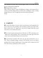
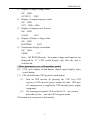
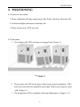
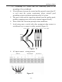
CONTENTS
CONTENTS
CONTENTS....................................................................................................... 1
1
INTRODUCTION ..................................................................................... 2
2
SAFETY .................................................................................................... 3
3
APPEARANCE ......................................................................................... 4
4
POSITIONING .......................................................................................... 7
5
INSTALLATION ..................................................................................... 10
6
OPERATION ........................................................................................... 14
7
STATUS HANDLING ............................................................................. 17
8
WORKING FLOW .................................................................................. 25
9
Monitoring software................................................................................. 27
10
Technical specification......................................................................... 29
11 Shipping list ............................................................................................. 31
-1-
INTRODUCTION
1 INTRODUCTION
1.1 Thanks
Thank you for your purchasing of Kstar UPS, its design is safe, reliable and
needless to maintain.
1.2 Reading
Please read this manual, it contains safe installation and operating introduction.
It helps you to get the optimal using life and service. The manual recounts UPS
internal working way and relative protection function.
1.3 Brief introduction
Master series on-line UPS is a new generation intelligent-type UPS specially
designed for finance system, telecom system, electric power system, intelligent
building, working station to meet the high quality and high reliability
requirement of the system to power supply.
1.4 Characteristic
●computer port
UPS intelligent monitoring function can be got by the computer port. The
detail refers to the Section 9 and UPS intelligent monitoring software user
manual.
●LCD display
The running status, load capacity and battery capacity are clear at a glance on
LCD on UPS control panel. You can master the change of UPS power supply
quality of and running environment at any time.
●electron bypass switch
When UPS is faulty, the bypass will be activated at once and supply power to
-2-
SAFETY
load through the built-in static electron bypass switch, at the same time the
buzzer sounds alarm for long-time.
●intelligent battery charger
When UPS has found AC input, the high-power charger can automatically be
started up and float charge battery circularly after extending for 10ms, avoiding
mangle because it can’t be supplied in time after battery discharged.
Safety
2 SAFETY
●To reduce the danger of electric shock caused because load equipment isn’t
good connected to the grounding, when installing computer port signal cable,
please switch off the AC input power, only after all signal cables have good
connected, you can connect the power.
●There must be proper branch protector (Breaker) on UPS connecting to AC
input power with grounding. That of connecting to any other type socket will
cause electric shock and infringe local electrical rule.
●Do not attempt to maintain UPS, there isn’t any parts maintained by user in
UPS. There is potential damage voltage in UPS and the services can only be
performed by the trained regular person. If user make bold to maintain and refit
UPS, the warranty qualification will be canceled.
-3-
APPEARANCE
3 APPEARANCE
3.1. Display/Control panel(Figure 1)
1) Welcome screen
WELCOME
TO
×××××××××
2) Display of system status
×××××
××KVA.
3) Display of input voltage value*
ON LINE
AC
IN: 220V
4) Display of input frequency value*
ON LINE
AC
FRE:50Hz
-4-
APPEARANCE
5) Display of output voltage value*
ON LINE
OUTPUT: 220V
6) Display of output frequency value
ON LINE
OUT FRE:50Hz
7) Display of output power Percent
ON LINE
LOAD:
80%
8) Display of battery voltage value
ON LINE
BATTERY:
218V
9) Temperature display in machine
ON LINE
TEMP:
33℃
Note:ON BYPASS mode,the output voltage and frequency are
displayed be “0” .LED would display only after the unit is
switched on.
*These parameters vary with machine model.
10) LCD cycle display switch button: digital signal display items
switch button.
11) UPS switch button: UPS general switch button.
(1) Turn on UPS inverter by pressing the “ON” key. UPS
convert to UPS inverter power output 20s later, UPS pure
AC output power is supplied by UPS internal power supply
equipment.
(2)
By keeping pressing the OFF switch for 3s,we can shut
down the inverter,turn the UPS to bypass mode.
The button acts as general switch mainly.
-5-
APPEARANCE
3.2. Machine appearance (Figure 2)
Figure 2
1). Display/Control panel.
2). Scattering heat ventilation hole:
The ventilation hole and other small long elliptic ventilation holes all need
to keep good ventilation.
3). RS232 communication interface receptacle.
The standard communication interface between UPS and computer.
4). Air blower.
5). Battery Switch.
6). MAIN INPUT switch
7). Wiring Terminal support
Power wiring Terminal support of input, output and battery.
8). Wiring inlet/outlet hole:
Wiring inlet/outlet hole of input, output and battery group
9). Active wheel:
There are four hidden active wheel, in favor of movement.
-6-
POSITIONING
4 POSITIONING
4.1 Transit or movement
1. Please dismantle all barge-connecting cable firstly. (Perform after turn off)
2. Careful and light placement, forbid any hit.
3. Please do not move UPS inverted.
4.2 Placement
1. Do not place the UPS on slope or scraggy land. (Figure 3)
Figure 3
2. Please place the UPS in the place where keeps good ventilation, UPS’s
back face and side face should be more than 10cm away from the room
wall. (Figure 4)
3. Do not position UPS in sunshine, drain and damp place. (Figure 5, 6)
-7-
POSITIONING
Figure 4
Figure 5
Figure 6
4. Please keep UPS away from fire source and high temperature avoiding
over-high temperature. (Figure 7)
5. Do not lay goods on the UPS. (Figure 8)
-8-
POSITIONING
6. Do not position UPS in the place where contains caustic gas. (Figure 9)
7. Running environment temperature: 0℃-40℃
Figure 7
Figure 8
Figure 9
-9-
INSTALLATION
5 INSTALLATION
5.1
AC Input
1. Prohibit using general household receptacle, because the Max
current of general receptacle is 15A, the socket may be burned down
for overload.
2. Please connect UPS input terminal to utility power switchboard
close. (Figure 10).
Figure 10
Note: Don’t make anti-connection of polarity
3. Simple identification way of power polarity:
(1) Firing line (R, S,T): There is 380V voltage between Line and
Line.
(2) Neutral (N): there is 220V voltage to Firingline, there is 0.5-2V
voltage to Grounding.
- 10 -
INSTALLATION
(3) Grounding (G): Please find real connecting point to the
grounding of the switchboard.
4. If the difference between the neutral and the ground is more than 5V
or can’t meet the system requirement, please reinstall good
grounding system to maintain operating safety of system.
5. The power cable and the impaction terminal must be quality goods,
prohibit wrapping power cable on the terminal support directly.
6. Please follow the electrician principle when installation.
7. Avoid using same a switch with other equipment when connect to
switchboard, try to connect to utility terminal.(Figure 11)
3ф4w+GND
Power utility 3 phase 4 wire input
Figure
8. AC input connect
AC INPUT
wiring position
Figure 12
- 11 -
11
INSTALLATION
5.2 AC Output
1. Please consult input installation principle about output principle.
2. Output power cable is designed according to load current, do not use
over-thin cable.
3. Avoid short-circuit and overload.
4. The grounding to the unit only acts as reference point, if the grounding
isn’t good, that may cause disturbance and false datum management and
affect UPS and computer, please ask professional personnel for handling
immediately.
5. User offers a good grounding system.
6. Try to make the grounding close to connection point of grounding club or
start point in switchboard.
7. AC OUTPUT connect wiring position(Figure 13)
Figure
13
AC
- 12 -
OUTPUT
INSTALLATION
5.3
DC input wiring
1. DC input connection please refer to AC input installation rules.
2. Connection way and position, please refer to figure 14.
Figure
14
Battery wire
5.4 Connecting position and way
1. Remove the cover screw on wiring terminal support with Philip Head.
2. Remove the cover and find the wiring terminal plate below the power switch.
3. According to connecting guide, draw AC power input cable, output cable
and battery pack power cable though the wiring outlet/inlet, then connect
to relevant terminal.
4. After connection, please carefully confirm if the connection is correct and firm.
5. After connection is correction, please relock the cover.
- 13 -
OPERATION
6 OPERATION
6.1 Preparing process before start-up.
To make UPS normal and correct running, please confirm the following
items. (Refer to figure 2)
3. Verify electric power switch on back panel is in the ‘OFF” position.
4. Verify the installation place again. (Figure 4 to 10)
5. Rock power cable with hand and see if there is any looseness, if
looseness, retighten the seizure screw.
6. Do not connect load.
7. Inspect input voltage is to meet the demand of UPS (220V±10%) with
ammeter.
6.2 Operation process at first start-up
After verify above items are correct, please start up UPS according to the
following ways:
1. Please switch electric power switch NO FUSE BREAKER (NFB) on the
back panel to the “ON” position. Input indicator light and bypass indicator
light on the front panel are lit on at the same time. As follows figure 15.
Figure 15
- 14 -
OPERATION
2. Plug the switch ON button on
front panel. As follow drawing.
The input indicator light and the
bypass indicator light are on
continuously. LCD display is lit.
Utility supplies power to output
via bypass.
Figure 16
3. After 20s, input indicator light
on front panel is lit, bypass indicator light is off, output indicator light is on the welcoming information is displayed on LCD ,
UPS inverter supplies power to
output.
Figure 17
4. Shutdown input power of UPS,
utility indicator light is off, the
welcoming information is
displayed on LCD, UPS inverter
supplies power to output., as
follow drawing. UPS sounds
every four seconds, which
indicates battery pack supplies
power to UPS at present. The
sound will automatically stop
90slater.
Figure 18
- 15 -
OPERATION
UPS will sound alarm every 1s again when battery power is to be exhausted.
5. Utility indicator light will be on when UPS input power source is resumed.
Plug the LCD display cycle switch button to switch items displayed, see if
display value is normal, thus first start-up procedure has been completed.
Please measure output voltage and see if it meets the requirement, then connect
load to UPS output terminal. Use pure power provided by UPS formally.
6. After connect load, plug LCD display cycle switch button to switch items
displayed till display the item of output power display percent %. If the value
displayed is more than 100%, please dismantle the unimportant load till the
value displayed is less than 100%.
6.3 Daily switch ON/OFF operation procedure
If you want to switch on/off during daily using, please operate UPS according
to the following ways:
1. If you want to switch off UPS, you can switch off UPS by plugging the
“OFF’ button located on front panel. At the time UPS is under bypass condition,
utility supplies power to output and the batteries are under charging condition.
2. Always turn on UPS by plugging down the “OFF’ button when daily
operation.
6.4 Switch ON/OFF operation procedure when UPS hasn’t been will be
not used for long-time.
1. If the time in during UPS will be not used exceeds ten days, please first turn
off UPS by pushing the “off” button on front panel, then position the NFB on
back panel the position of “OFF”.
2. If the time that UPS doesn’t be used exceeds three months, please run UPS
for above 24 hours according to the process of first start-up and make the
battery on the full electrical position and extend battery life.
- 16 -
STATUS HANDLING
7 STATUS HANDLING
7.1. Symbol indicator:
Note: If indicator light flash, the flash period is synchronal with that of buzzer
sounds
7.2 UPS run status indicator and handling ways when normal
Please refer to indicator, LCD indicator value and buzzer sound on the panel,
you can see if UPS running is normal, if UPS is abnormal, please refer to the
handling thing according to panel
indicator status.
1. Panel indicator status is as the
right:
(1) UPS running status:
Utility is normal, UPS runs
normally and UPS is used under
full-load.
(2) Handling way: needless
handling.
Figure 19
2. panel indicator status is right:
(1)UPS running status:
Utility is normal, UPS runs
normally and battery capacitor is
above 90%.
(2) Handling way: needless
handling.
Figure 20
- 17 -
STATUS HANDLING
3. panel indicator status is right:
(1) UPS running status:
Utility supplies power 220Vac
normally and UPS runs normally.
(2)Handling way:
needless handling.
Figure 21
4. panel indicator status is right:
(1)UPS running status:
Utility supplies power normally,
UPS runs normally and battery
voltage is low.
(2)Handling way: needless handling.
The charger is fault, please replace
charging board.
Note: the indicated material
parameters vary with
the machine type.
Figure 22
5. panel indicator status is right:
(1)UPS running status
Utility power is normal and it is
transferred to utility mode. UPS
don’t start up until the startup
button on the panel of UPS is
pressed.
(2)Handling way: please deal with
it reference to status dealing flow
chart 2.
Figure 23
- 18 -
STATUS HANDLING
6. Panel indicator status is right:
(1)UPS running status:
Utility supplies power. Under
overload 125%, overload indicator
light is solid on and the buzzer
beeps continuously.
(2)Handing way:
Please release load to ensure the
indicated percent of LCD output
power is less than 100%. If the thing
is still present after removing
load, please refer to flow chart 3
of status handling.
Figure 24
7. Panel indicator status is right:
(1)UPS running status:
Utility power is normal, UPS runs
abnormally and transfers to be
supplied power by utility.
(2)Handling way:
Please refer to flow chart 4 of
status handling.
Figure 25
8. Panel indicator status is right:
(1)UPS running status:
Utility power is disconnected, UPS
is supplied power by battery and
load is full load. Buzzer beeps once
every fo- ur seconds.
The battery energy indicator light
fla- shes every four seconds (buzzer
Figure 26
- 19 -
STATUS HANDLING
and indicator light stop beep and flash.
(2)Handling way:
If utility is disconnected normally, please remove non-critical loads to increase
used time. If it is disconnected abnormally, please refer to flow chart 1 of status
handling.
9. panel indicator status is right:
(1)UPS running status:
Utility power is disconnected and
UPS is supplied power by battery.
Buzzer beeps once every one second when the battery power will be
exhausted.
(2)Handling way:
UPS will shutdown at once, please
save files as you could.
Figure 27
10. Panel indicator status is right:
(1)UPS running status:
Utility power may have been
disconnected and battery power has
been exhausted, UPS shutdown
automatically.
(2)Handling way:
Waiting for utility power
connecting and then UPS will
automatically startup.
Figure 28
If utility power is disconnected for long period of time, please turn off UPS
according to switch on/off program for power cut of long period of time
- 20 -
STATUS HANDLING
Flow chart 1 of status handing
- 21 -
STATUS HANDLING
Flow chart 2 of status handing
- 22 -
STATUS HANDLING
Flow chart 3 of status handing
- 23 -
STATUS HANDLING
Flow chart 4 of status handing
- 24 -
WORKING FLOW
8 WORKING FLOW
8.1 UPS system configuration block figure: figure 29
Figure 29
8.2 UPS’s running way when UPS runs normally
When UPS runs normally, after high-frequency harmonic noise in utility power
is filtered by the filter, on the one hand utility power charges battery pack via
the inverter and keeps battery power on full voltage level and on the other hand
utility power is converted into direct current via the rectifier and is transferred
into pure sine ware power via the inverter, finally power is transmitted to user
equipment for using via the static switch and the filter. As figure 30.
Figure 30
- 25 -
WORKING FLOW
8.3 UPS’s running way when utility power is disconnected
As figure 31, when utility power is disconnected, power is supplied to the
inverter by the battery and then is transmitted to user equipment for using via
the static switch and the filter to avoid the case that load isn’t supplied power.
Figure 31
8.4 UPS’s running way when UPS supplies power on bypass mode
There are five kinds of status when UPS supplies power on bypass mode. As
figure 32
1.overload
2. inverter failure
3.when switch on, UPS is in the course of slow startup during pressing the
“SWITCH ON” button for 20 seconds
4.When switch off, please press the “SWITCH OFF” button.
5.UPS runs under the condition of internal over-temperature.
Figure 32
- 26 -
Monitoring software
9 Monitoring software
9.1. Summarize
UPS can offer the function of communication and command with computer.
To avoid data loss or damage, computer needs some time to close system in an
orderly way. When external power is disconnected, the computer system
protected by UPS finally still is closed lawless because of losing power when
battery has been exhausted. Through monitoring software, UPS can
communicate with computer system so as to inform computer system to close
computer systematically when UPS battery will be exhausted.
9.2 Software
When the server is unguarded, the power thing record and the function of
informing turn off, control and auto startup can be achieved through UPS
intelligent monitoring software. The software is suit to most operation system,
a signal cable with software. The detail refers to UPS intelligent monitoring
software user manual.
Figure 33
- 27 -
Monitoring software
9.3 port component
To computer system with built-in UPS monitoring software, the port
component can connect UPS into your system. Each component includes
relevant port cable that convert UPS status signal into identifiable signal to
system. (only using UPS monitoring cable supplied by factory)
PIN2: RS232 RXD
PIN3: RS232 TXD
PIN5: GND
Figure 34
- 28 -
Technical specification
10 Technical specification
Capacity
6KVA
8KVA 10KVA 12KVA 15KVA 20KVA 25KVA 30KVA
AC input
Voltage
380VAC±20%
Frequency
50 (60)Hz±5%
Phase
Max.current
Three phases + Grounding
10A
13A
16A
20A
24A
32A
40A
56A
AC output
Voltage
220V
Frequency
50 (60)Hz
Voltage
±1%
frequency
±0.5% (When disconnection)
Wave form
SPWM sine wave
Power factor
distortion
0.8
Later
<3% (linear load)
Battery
Voltage
192VDC
Model
Lead –acid free maintenance
Charging time
90% capacity after 8-10 hours
240VDC
Alarm
Utility disconnect
Buzzer beeps once every four seconds
Battery exhausted
Buzzer beeps once every one second
Overload
Overload indicator light is solid on, buzzer continuously beeps for
long-time.
UPS abnormal
Fault indicator light is solid on, buzzer continuously beeps for long-time.
- 29 -
Technical specification
Capacity
6KVA
8KVA 10KVA 12KVA 15KVA 20KVA 25KVA 30KVA
Internal protection equipment and LCD panel
Battery
UPS automatically shutdowns when battery is low power level, there is
no fuse switch protection.
Overload
When load reaches 110~150% of rating, transfer to bypass after 30s,
recover auto after unload.
Over-temperature
Automatically transfer to bypass if UPS internal temperature > 85℃
Output
Limit current, automatic shutdown, fuse and there no fuse switch
short-circuit
protection.
UPS abnormal
Automatically transfer to bypass and supplied power by utility
Noise filter
10~100KHz at 40Db; 100KHz~100MHz at 70dB
LCD display
input, output voltage, frequency, battery voltage, output power (%),
Battery BVL
One LED, it lit on when battery low voltage
temperature
Environment
Temperature
0~40℃
Humidity
0~95%, non-condensing
Noise
<58dB (1m)
General
Output socket
Unit weight
Dimension (mm)
Terminal plate
118Kg
128Kg
155Kg
165Kg
262Kg
305×585×864
297Kg
326Kg
725×430×1180
others
Full efficiency
>85%
Transform time
0ms
UPS status
Utility, inverter, bypass, UPS abnormal (fault)
indicator
Communication
RS232 interface of DB9 model
interface
- 30 -
336Kg
Shipping list
11 Shipping list
code
Content
Number
1
UPS
1
2
«UPS use manual»
1
3
Intelligent monitoring software
1
4
Computer port cable RS232
1
- 31 -