1
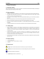
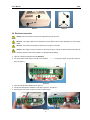
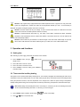
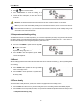
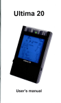
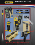
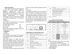
User’s Manual
SP26
Table of Contents
1
General information······································································································2
1.1
1.2
1.3
1.4
1.5
1.6
1.7
About this manual ································································································································· 2
Safety regulations ································································································································· 2
Liability waiver······································································································································· 2
Scope of delivery ·································································································································· 2
Symbols used ······································································································································· 2
Technical data ······································································································································· 3
Case overview ······································································································································ 3
2
Installation·····················································································································3
2.1
2.2
Mounting ··············································································································································· 3
Electrical connection····························································································································· 4
3
Operation and functions ······························································································5
3.1
3.2
3.3
3.4
Setting time ··········································································································································· 5
Time controlled auxiliary heating ·········································································································· 5
Temperature maintaining setting ·········································································································· 6
Reset····················································································································································· 6
3.5
Force heating ········································································································································ 6
4
Error messages·············································································································7
1
User’s Manual
SP26
1 General information
1.1 About this manual
This manual describes the installation, function and operation of a solar thermal controller. Before installing and operating the
controller, please read the following information carefully.
1.2 Safety regulations
•
Installation, commissioning and maintenance of the controller may only be performed by trained professional personal.
•
All operations that require opening the device are only to be conducted cleared from the power supply. All safety
regulations for working on the power supply are valid.
•
The controller must not be installed in rooms where easily inflammable material (e.g. gas or oil) mixtures are present or
may occur.
•
Before connecting the device, make sure that the energy supply matches the specifications of controller.
•
All devices connected to the controller must conform to the technical specifications of the controller.
•
As soon as it becomes evident that safe operation is no longer possible, please take the device out of operation
immediately.
•
It is strongly recommended not to use this device in thunderstorm, unless the building has thunder protection.
1.3 Liability waiver
•
Improper installation or operation can cause damages to material and persons. The manufacturer cannot monitor the
compliance with these instructions or the circumstances and methods used for installation, operation, utilization and
maintenance of this controller. Damage by mishandling or improper installation on costumer site is immediately leading
to warranty exclusion.
•
As faults can never be excluded, we don’t offer a guarantee for the completeness of the drawings and texts of this
manual, they only represent some examples. They can only be used on own risk. No liability is assumed for incorrect,
incomplete or false information and the resulting damages.
•
The manufacturer preserves the right to put changes to product, technical date or installation and operation instructions
without prior notice.
1.4 Scope of delivery
•
1×Solar Controller SP26;
•
1×Sensor NTC 10K; 1×Power connection; 3×Screws;
•
1×Manual
1.5 Symbols used
Danger: Failure to observe these instructions can lead to injury of persons or safety risks.
Attention: Failure to observe these instructions can result in damage to the product or environment.
Note: Useful information and instructions.
†
Operation steps: Indication of operation step.
2
User’s Manual
SP26
1.6 Technical data
•
•
•
Display dimension: 170mm x148mm x40mm
•
•
•
•
•
Accuracy of temperature measuring: ± 1℃
Power supply:AC220V±20% or AC110V±20% (must be noted in order)
Power consumption:≤ 3W
Range of temperature measuring: 0℃ - 99℃
Suitable power of electrical booster:standard ≤ 2000W, selectable variant ≤ 3000W (must be noted in order)
Ambient temperature :-10℃ ~ 50℃
Water proof grade:IP40
1.7 Case overview
System controller
1
Adjust
6
2
Confirm
Cancel
5
3
4
Adjust
No.
1
2
3
4
5
6
Button
Display
Adjust “ ”
Cancel
Adjust “ ”
Confirm
ON/OFF
2 Installation
2.1 Mounting
Attention: Controller must only be located internally and must have an adequate level of protection.
Attention: Don’t drill holes on the case of controller.
†
Loose the screw ① completely and remove the upper part of the controller in the upwards direction ②, see picture 1.
†
Choose a mounting place and fix a screw on the wall for ③, see picture 2.
†
†
Hang the controller in position ③.
Make sure of the position for the other two holes ④ on the wall, and fix the controller by means of the enclosed screws.
3
User’s Manual
†
SP26
Replace the upper cover of the controller.
②
③
④
①
Picture 1
Picture 2
2.2 Electrical connection
Danger: Remove the device from the power supply before opening the case!
Attention: Low-voltage cables such as temperature sensor cables must be routed separately from mains voltage
cables.
Attention: The protective conducting wire (earth wire) must also be connected.
Danger: Power supply can only be switched on when the housing of controller is closed, installer must make sure
that the IP protection class of the controller is not damaged during installing.
†
Open the controller as described under 2.1 Mounting.
†
Cut off the plastic sheets from the controller case in position ⑥ or ⑦ for routing the cables, using a sharp scissor or
knife, see picture 3.
⑦
⑥
Picture 3
†
Open the terminals with suitable tools, see picture 4.
†
Connect the cables like the indications in “terminals connection”, see picture 5.
†
Refit the upper cover of the controller and switch on power supply.
Picture 4
4
User’s Manual
SP26
Picture 5
Attention: Only original factory equipped NTC10K, B=3950 temperature sensor is approved for using in the solar
system, it is equipped with 1.5 meter PVC cable, and it is temperature resistant up to 105℃. It’s not necessary to
distinguish the positive and negative polarity of the sensor connection.
Attention: All sensor cables can carry low voltage, in order to avoid inductive effect, the cables must not be laid
close to 230 volt or 400 volt cables (minimum distance of 100mm).
Attention: If external inductive effect exists, e.g. from heavy current cables, overhead train cables, transformer
substations, radio and television devices, amateur radio stations or microwave devices etc., then the cables for the
sensors must be adequately shielded.
Attention: Sensor cables may be extended to a maximum length of 100 meter. When cable's length is up to 50m,
then 0.75mm² cable should be used. When cable's length is up to 100m, then 1.5mm² cable should be used.
3 Operation and functions
3.1 Setting time
After switching on power supply, please firstly set the time of the controller.
†
Press “ON/OFF” button, the sign “
” shows on the
display screen.
†
Press “▲” button to set hour of clock.
†
Press “▼” button to set minute of clock.
†
Press “Confirm” to save the setting, press “Cancel” to
cancel the setting.
3.2 Time controlled auxiliary heating
Solar system can be combined with auxiliary heating devices. The controller is equipped with a default program which can be
customized to meet your individual needs. You can create a timer program with up to three time sections for heating the water.
During the preset time sections, when the temperature of the storage tank is below the preset turning-on temperature,
auxiliary heating starts working; when the temperature exceeds the preset turning-off temperature, electrical booster stops.
Note: Default setting: the first heating time section: 4:00 turning on, 5:00 turning off; the second heating time section:
10:00~10:00; the third heating time section: 17:00 turning on, 22:00 turning off.
†
Press “ON/OFF” button repeated, until the signal “
†
Press “ ” “ ” button to set the start time.
” shows on the display.
5
User’s Manual
SP26
†
Press “Confirm” button to confirm the setting, and it enters directly into the end time setting.
†
Press “ ” “ ” button to set the end time.
†
Press “Confirm” button to confirm the setting, and it
enters directly into the second time section setting.
†
Perform like above description, the other time sections
can be set.
Attention: All of these three time sections must be set at one time, thuswise the settings can be saved.
Note: If you want to shut off the auxiliary heating in one of the three time sections, then you can set a same value for
both start time and end time (e.g. if you set both start and end time at 10:00 hour, then the auxiliary heating in the
second time section will not be triggered).
3.3 Temperature maintaining setting
To maintain the tank water at a certain temperature, you can set the required value previously. During the three time sections
for auxiliary heating, if the water temperature falls below the turning-on temperature (default value: 55℃,△ON=△OFF-5℃),
the water will be heated up to the turning-off temperature (default value: 60℃).
†
Press the button “ON/OFF“ repeated until the signal “60
℃” displays on the screen.
†
Press “
†
Press “Confirm” to save the adjustment, press ”Cancel”
” and “
” button to adjust the required
temperature. Setting range: 45℃-75℃.
to cancel the adjustment.
3.4 Reset
All of the settings (besides the time setting) that have been made can be reset, if it is necessary (e.g. when system program is
out of working).
†
Press “ON/OFF” button repeated until the sign “AUTO”
shows on the display screen.
†
Press “Confirm” to set the parameters of system back to
the factory settings.
†
Press “Cancel” to cancel the reset function.
3.5 Force heating
To heat the water manually whenever you want, the controller is equipped with a force heating function.
†
Press “Confirm” button when not in any of above setting menus, the force heating function is immediately triggered.
†
Press “Cancel” button to stop heating the water, or it stops until the water tank temperature reaches the value you set in
3.3 Temperature maintaining setting.
6
User’s Manual
SP26
4 Error messages
Danger: Never try to repair the controller yourself! Consult a specialist in case of an error!
If there is a problem with the controller or temperature sensor, the error messages will be displayed on the screen. The
following table explains the error messages and corresponding handling indication. Most of the problems can be found in the
list below.
Error message
Possible cause
Handling
Nothing shows on the display.
Controller power supply is interrupted.
Check the controller power connection.
The signal <FF> shows on the
Temperature sensor is out of service.
Check the connection or resistance value of
display.
the sensor.
Note: Sensor characteristics are listed in the following tables.
NTC 10K B=3950 resistance value
℃
0
10
20
30
40
50
60
70
80
90
100
110
120
Ω
33620
20174
12535
8037
5301
3588
2486
1759
1270
933
697
529
407
7