1
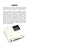
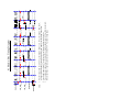
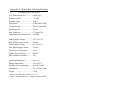
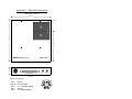
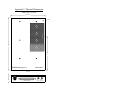
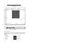
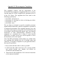
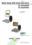
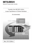
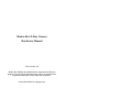
Shad-o-Box X-Ray Camera
Hardware Manual
P/N 1015 Rev. 08
Shad-o-Box, RadEye and ShadoCam are trademarks of Rad-icon
Imaging Corp. All other brand and product names are trademarks or
registered trademarks of their respective companies.
© 2001-2004 Rad-icon Imaging Corp.
1. Introduction
The Shad-o-Box x-ray camera is a stand-alone, high-resolution
radiation imaging device complete with 12-bit digital interface.
Typical uses include a wide range of applications such as
industrial, biomedical and scientific x-ray imaging. The heart of
each Shad-o-Box camera is a two-dimensional photodiode array
containing up to 2048 by 2000 pixels on 48 µm centers. An
integral phosphor screen shields the sensor from ambient light
and converts incident x-rays or energetic particles to visible
light that is sensed by the silicon photodiodes. The Shad-o-Box
also includes electronics to digitize the video signal, a camera
controller to generate the appropriate timing signals, and a
digital interface to connect to a frame grabber inside a PC.
Together with our ShadoCam software for image acquisition
and display, or other third-party Windows software, the Shad-oBox x-ray camera provides a user-friendly solution for highresolution digital radiography.
This manual provides an overview of the Shad-o-Box
installation process and the operation of the camera. Additional
information is also available from your frame grabber
manufacturer. The components that were shipped with your
Shad-o-Box camera have been tested to ensure that they work
together properly. However, due to the large variety of PC
hardware and software in existence it is quite impossible to test
every combination of components to ensure full compatibility.
A Pentium II processor with 64 MB of memory and running
under Windows 98 has consistently achieved good results,
although a faster PC with at least 128 MB and Windows XP is
recommended.
The Shad-o-Box digital interface is compatible with most
commercially available digital frame grabbers. Frame grabber
manufacturers typically provide custom software drivers, setup
utilities and imaging software with their products. Some
manufacturers also offer LabView or TWAIN drivers for their
boards. A custom data cable is usually required. Rad-icon's
ShadoCam software for image acquisition and display is
constantly being upgraded to support additional frame grabber
models. Please contact your sales representative for information
on which commercial frame grabbers are currently supported
(see back of manual for contact information).
2. Camera Installation
The Shad-o-Box x-ray camera is designed to work together with
a digital frame grabber in order to acquire images into a
computer. Please refer to your frame grabber user's manual for
instructions on how to install the frame grabber board and its
device driver. You should verify that your frame grabber is set
up correctly before attempting to connect it to the Shad-o-Box
camera.
If you purchased your frame grabber along with the Shad-o-Box
camera directly from Rad-icon, a data cable to connect the
frame grabber board to the camera was most likely included in
your order. If not, you may need a custom cable to interface
your frame grabber to the Shad-o-Box camera. Please refer to
the connector pin assignment table listed in Appendix B for
connecting the Shad-o-Box signals to your frame grabber.
Using the data cable, connect the frame grabber to the parallel
interface (the 68-pin mini-D receptacle) on the camera. You
may also connect an external frame sync source to control the
camera's frame rate to the SMA receptacle next to the parallel
interface. You can monitor the camera's frame sync output at
the second SMA receptacle on the camera's front panel.
Connect the plug from the power supply that was shipped with
your Shad-o-Box camera to the receptacle on the camera's front
panel. Plug the power supply into a grounded wall outlet or
power strip. The camera will start up automatically and begin
transferring frames to the computer (unless one of the external
frame sync inputs is pulled low). To turn off the camera, unplug
the power supply or use the switch on your power strip. Do not
attempt to switch the camera on or off by inserting/removing
the power connector on the camera, as this may disrupt the
camera's auto-initialization sequence.
3. Software Installation
Your Shad-o-Box x-ray camera ships with a CD containing a
PDF version of this manual, an installation file for the
ShadoCam image acquisition and display software, a factorycalibrated pixel map for your camera, as well as data sheets and
other useful information.
3.1 Installing ShadoCam
The ShadoCam image acquisition and display software works
with your Shad-o-Box camera and your frame grabber to let you
acquire, display and save images within minutes. To install
ShadoCam, place the CD in your computer's CD drive and
follow the prompts from the installation menu.
When starting up ShadoCam for the first time, make sure to
select the Preference dialog from the Acquisition menu. Adjust
the settings for your hardware and your imaging preferences.
For instructions on preference settings and other program
functions please refer to the extensive ShadoCam help file that
is installed with the program. You can also check our website
(www.rad-icon.com) for the latest updates.
3.2 Preparing the Pixel Map
Your Shad-o-Box camera comes with a factory-calibrated pixel
map that works with ShadoCam to automatically perform pixel
corrections on any acquired images. This pixel map needs to be
copied into ShadoCam's default data directory where the
program can access it (e.g. "C:\Program Files\ShadoCam").
You can edit the pixel map in ShadoCam to suit your specific
requirements. Make sure to create a back-up copy of the
factory-supplied pixel map in a safe location on your hard drive
so you can revert to it if necessary. For more information on
pixel maps and image corrections please refer to the help file.
4. Camera Operation and Timing
As shown in the block diagram below, the Shad-o-Box camera
consists of one or more RadEye sensors, an analog-to-digital
(A/D) interface, a digital controller, and the frame grabber
interface. The controller generates all the timing signals needed
to run the sensors and digitize the video signal. The A/D
interface consists of a gain/offset adjustment stage and a 12-bit
A/D converter for each sensor. The frame grabber interface
consists of RS-422 or EIA-644 (LVDS) drivers and receivers
(depending on the camera model) that communicate with the
frame grabber board in your.
SMA
control
fr. sync out
RadEye1
gain
12-bit
A/D
Camera
Controller
FPGA
offset
adj.
RadEye1
(Shad-o-Box 1024)
gain
offset
adj.
ext. sync in
data
12-bit
A/D
F.G.
Inter
face
68-pin
miniD
conn.
+5/12V
+5V
or
+12V
+6.5V
Gnd
GND
Shad-o-Box
Shad-o-Box
1536/2048
1536/2048/4K
power
Each RadEye sensor in the Shad-o-Box image area is scanned
independently through one or more parallel channels. The row
scan starts at the top of the active area and scans toward the
bottom. Depending on the camera model, each line is scanned
in one or more sections, starting at the left and moving towards
the right (see figure on next page). The video data from multiple
sections are interleaved for transmission. In this case the pixels
need to be deinterlaced in the frame grabber or in software to
restore the image.
Shad-o-Box Image Scan
row 1
row scan
col 2048
row scan
col 512
column scan
row scan
col 1
row scan
column scan
col 1536
column scan
col 1024
column scan
...Shad-o-Box 1024
...Shad-o-Box 1536
...Shad-o-Box 2048
row 1024
Shad-o-Box 512
The camera frame rate can be controlled via the external frame
sync inputs on either the parallel interface (EXSYNC) or the
SMA receptacle next to it. If these inputs are pulled high (SMA
not connected) the camera will run continuously at its maximum
frame rate of 2.7 fps. If either one of the frame sync inputs is
pulled low, the camera controller will wait for a rising edge on
this input before starting the next frame readout. To avoid
conflicts, only one of these inputs should be used at a time.
Depending on the model of your Shad-o-Box camera, the data
rate at the parallel interface can vary from 1.5 MHz up to 12.0
MHz. The digital data on the parallel interface are valid when
both the line enable (LN_EN) and the pixel clock (PXCLK)
signals are high. However, the first 2.7 µs in each line are
blanked to provide time for the frame grabber to synchronize to
the camera's signal.
The pixel clock runs continuously. To minimize transmission
errors, the data should be sampled on its falling edge. The line
enable signal goes low for 14.0 µs during the horizontal
blanking interval. It is also low for a minimum of 16.0 µs
between frames. Frame enable (FR_EN) goes low during the
vertical blanking interval to signal the beginning of a new frame
(see timing diagram on next page).
notes:
EXSYNC
Data
LN_EN
FR_EN
PXCLK
2.7
µs
16.7 µs
Row1
341.3 µs
2.7
µs
16.7 µs
Row2
341.3 µs
Row1024
341.3 µs
> 2 µs
~5
µs
2.7
µs
16.7 µs
1. Pixel Clock period (T) is 0.667µs for Shad-o-Box 512, 0.333µs for Shad-o-Box 1024,
0.167µs for Shad-o-Box 1536/2048 models, and 0.083µs for the Shad-o-Box 4K.
2. Line Enable goes high 2.7µs before first valid pixel appears on data bus.
3. For continuous readout leave External Sync high (readout restarts 2.0µs after last pixel).
If External Sync is pulsed, readout starts within 4.3-5.0 µs after rising edge.
min
10µs
T
4.1 Shad-o-Box Timing Diagram
Row1
341.3 µs
5. Frame Grabber Information
Please check our website for the latest list of supported frame
grabbers. Let us know if you have a specific frame grabber not
on the list that you would like to see supported.
5.1. Data Translation DT3157
The DT3157 runs in continuous mode by default (2.7 fps).
Longer exposures are achieved by first resetting the camera,
then waiting for the specified exposure time, and finally reading
the image. The DT3157 does this by first pulsing the SC_IN
(Camera Reset) line and then holding the EXSYNC line low for
the required exposure period. After the acquisition is complete,
the EXSYNC line reverts to its default logic high state. For
multiple exposures this process is repeated several times.
The camera exposure can be controlled more accurately by
using an external pulse generator on the external frame sync
input. If this is the case, make sure to set the frame exposure to
10 ms or less in order to disable the DT3157's exposure control.
Please note that the DT3157 frame grabber supports only the
Shad-o-Box 512 and 1024 camera models.
5.2. Imagenation PXD1000
The PXD1000 runs in continuous mode by default (2.7 fps). An
on-board pulse generator allows you to adjust the exposure time
up to 6.7 seconds. Each frame receives the same exposure time.
To use the external frame sync feature, make sure to set the
frame exposure to 10 ms or less in order to disable the
PXD1000's exposure control.
Appendix A: Shad-o-Box 1024 Specifications
(consult data sheet for other models)
Avg. dark current (23°C)*............8 ADU/sec**
Read noise (rms)..........................< 1 ADU
Dynamic range.............................4000:1
Digitization ..................................12 bits (4096 ADU)
Conversion gain...........................500 electrons/ADU
Readout period.............................367 ms
Max. frame rate ...........................2.7 frames/sec
Output data rate (at connector) ....3.0 MHz
Analog supply voltage.................12 V (±0.6 V)
Max. analog supply current .........150 mA
Digital supply voltage..................5 V (±0.25 V)
Max. digital supply current..........750 mA
Typical power dissipation............4.5 W
Parallel digital interface...............RS-422
SMA connector interface.............TTL
Operating temperature .................0 to 50 °C
Storage temperature.....................-25 to +85 °C
Humidity (non-condensing).........10 to 80 % R.H.
Dimensions ..................................127 x 124 x 23 mm
Weight .........................................1.5 kg
* dark current doubles approximately every 8 °C
** ADU = Analog-Digital Unit ≡ 1 LSB (Least Significant Bit)
Appendix B: Parallel Interface
Pin Assignments:
Signal
Description
D15
D14
D13
D12
D11
D10
D9
D8
D7
D6
D5
D4
D3
D2
D1
D0
FR_EN
LN_EN
PXCLK
EXSYNC
SC_IN
SC_OUT
CTRL1
CTRL2
GND
Data Bit 15 (tied low)
Data Bit 14 (tied low)
Data Bit 13 (MSB)
Data Bit 12
Data Bit 11
Data Bit 10
Data Bit 9
Data Bit 8
Data Bit 7
Data Bit 6
Data Bit 5
Data Bit 4
Data Bit 3
Data Bit 2 (LSB)
Data Bit 1 (tied low)
Data Bit 0 (tied low)
Frame (vert.) Sync
Line (hor.) Sync
Pixel Clock
Ext. Frame Sync
Camera Reset
(rsrvd for future use)
Binning Control
(rsrvd for future use)
Signal Ground
I/O
+pin#
-pin#
O
2
36
O
3
37
O
4
38
O
5
39
O
6
40
O
7
41
O
8
42
O
9
43
O
10
44
O
11
45
O
13
47
O
14
48
O
15
49
O
16
50
O
19
53
O
20
54
O
25
59
O
26
60
O
29
63
I
30
64
I
23
57
O
22
56
I
31
65
I
32
66
pins 1,12,34,35,46,68
Note: Camera inputs (“I”) should be tied to logic “high” if not in use.
Data Connector:
68-pin mini-D (SCSI-3) receptacle
mating connector: AMP P/N 749621-7 (or equivalent)
shell: AMP P/N 786152-3 or 750752-1 (2-56 jackscrews)
Appendix C: Physical Dimensions
Shad-o-Box 512/1024
124.2 mm
5.6 mm
1
top of image
92.0 mm
127.0 mm
2
Rad-icon Imaging Corp
Shad-o-Box
TM
22.6 mm
top view
3
2
1
power
parallel interface
ext.
frame
sync in sync out
front view
Power Connector:
pin 1
pins 2,3
pin 4
pin 5
pin 6
ground
not connected
+12 V (analog supply)
ground
+5 V (digital supply)
6
5
3
4
2
1
Appendix C: Physical Dimensions
Shad-o-Box 1536/2048
124.2 mm
5.6 mm
1
top of image
2
184.9 mm
3
117.3 mm
4
Rad-icon Imaging Corp
Shad-o-Box
TM
22.6 mm
top view
power
parallel interface
front view
ext.
frame
sync in sync out
Appendix C: Physical Dimensions
Shad-o-Box 4K
263.7mm
101.6mm
91.6mm
207.5mm
top of image
100.3mm
81.0mm
Rad-icon Imaging Corp
Shad-o-Box
TM
19.4mm
power
parallel
interface
ext.
frame
sync in sync out
Power Connector:
DC power jack, 2.0 mm center pin diameter. Fits standard female
power plug with 2.1 mm inside diameter and 5.5 mm outside
diameter.
center pin:
6.5 VDC
Ø2.0 mm
outside:
ground
Ø6.5 mm
Appendix D: Electromagnetic Compliance
This equipment complies with the requirements of the
89/336/EEC Electromagnetic Compatibility Directive as well as
with the limits for a Class A digital device pursuant to Part 15
of the FCC Rules. The equipment has been tested to the
following specifications:
•
•
•
•
EN 55022: 1998 (Class A)
EN 61000-3-2: 1995 plus A1:1998, A2:1998 & prA14:2000
EN 61000-3-3: 1995
EN 55024: 1998
The test limits are designed to provide reasonable protection
against harmful interference when the equipment is operated in
a commercial environment. This equipment generates, uses, and
can radiate radio frequency energy and, if not installed and used
in accordance with the instruction manual, may cause harmful
interference to radio communications. Operation of this
equipment in a residential area is likely to cause harmful
interference, in which case the user will be required to correct
the interference at his own expense.
Note: The EMC performance of this product was verified under
test conditions that included the use of shielded cables and
connectors. To maximize compliance in your application follow
these specific guidelines:
• Keep control and data cables as short as possible.
• Control and data cables must have 95% coverage shields
that include braided wire. Metallic foil shields are
insufficient without braided wire.
•
Ensure that all cable shields have 360° electrical connection
to the connector backshell.
Contact Information
For technical assistance with the ShadoCam software or your
Shad-o-Box camera please contact our customer service
department (8 am to 6 pm PST) at 408-486-0886, or send us an
E-mail at "[email protected]". Please be prepared to give a
detailed description of your problem. Some of the information
we may need includes:
- The version of ShadoCam you have installed on your
system.
- The name and version of your operating system and
your BIOS.
- The type of hardware (CPU, PCI chipset, frame
grabber) you are using.
- The model number and serial number of the Shad-oBox camera you are using.
- The model number and version of the frame grabber
you are using.
For the latest information and updates please visit our web site
at "http://www.rad-icon.com".
Rad-icon Imaging Corp.
3193 Belick Street, Unit 1
Santa Clara, CA 95054-2404
tel. (408) 486-0886
fax (408) 486-0882