1
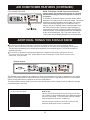
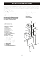
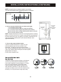
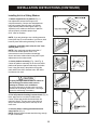
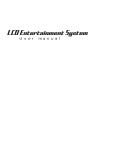
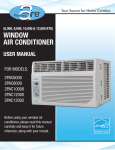
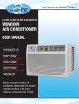
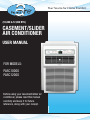
Your Source for Home Comfort
(10,000 & 12,000 BTU)
CASEMENT/SLIDER
AIR CONDITIONER
USER MANUAL
FOR MODELS:
PASC10000
PASC12000
Before using your casement/slider air
conditioner, please read this manual
carefully and keep it for future
reference, along with your receipt.
CONTENTS
SAFETY PRECAUTIONS ..................................................................................... 2
IMPORTANT SAFETY INSTRUCTIONS ...............................................................4
NORMAL SOUNDS .............................................................................................. 5
AIR CONDITIONER FEATURES..........................................................................6
INSTALLATION INSTRUCTIONS .......................................................................10
CARE AND CLEANING.......................................................................................18
TROUBLESHOOTING TIPS ............................................................................... 19
This manual provides the information needed for proper use and maintenance of this air
conditioner. Basic preventative care can help extend the life of this unit. The “Troubleshooting
Tips” section in this manual contains a chart with solutions to the most common problems.
Referring to this section may save time and prevent the need for a service call in the event of
a problem.
! CAUTION
●Contact an authorized service technician for repair or maintenance of this unit.
●Contact an installer for installation of this unit if necessary.
●The air conditioner is not intended for use by young children without supervision.
Young children should be supervised to ensure that they do not play with the air conditioner.
●Disabled persons may require assistance with set up.
●If the power cord is to be replaced, replacement work should be performed by authorized
personnel only.
●Installation and repair work must be performed in accordance with the national wiring
standards by authorized personnel only.
●Do not operate your air conditioner in a wet room such as a bathroom or laundry room.
●Units with a heating function should be at least 3 1/3 ft (1 meter) away from any combustible/
flammable materials.
NOTE: All the illustrations in this manual are for explanation purposes only. Unit purchased
may be slightly different.
The design and specifications are subject to change without prior notice for product
improvement. Contact customer service for details.
1
SAFETY PRECAUTIONS
To prevent injury to the user or other people and property damage, the following instructions
must be followed. Incorrect operation due to ignoring of instructions may cause harm or
damage. The seriousness is classified by the following indications.
!
!
WARNING
!
CAUTION
This symbol indicates the possibility of death or serious injury.
This symbol indicates the possibility of injury or damage to property.
Meanings of symbols used in this manual are as shown below.
!
!
Never do this.
Always do this.
!
!
!
Plug in power plug properly.
Do not operate or stop the unit
by inserting or pulling out the
power plug directly from the wall.
Failure to do so may cause
electric shock or fire due to
excess heat generation.
Doing so may cause electric
shock or fire due to heat generation.
Do not modify power cord
length or share the outlet with
other appliances.
Do not operate with wet hands
or in damp environment.
Do not direct airflow directly at
room occupants.
Always ensure effective
grounding.
Do not allow water to run into
electric parts.
!
grounding may cause
electric shock.
Doing so may cause failure of
machine or electric shock.
Incorrect installation may cause fire
and electric shock.
Always unplug the unit if
strange sounds, smell or
smoke comes from the unit.
Do not use the socket if it is
loose or damaged.
! Failure
to do so may cause fire
and electric shock.
! Doing
so may cause fire.
This could cause health issues.
Always install circuit breaker
and a dedicated power circuit.
Do not open the unit during
operation.
Doing so may cause fire and
electric shock.
Doing so may cause electric shock.
Do not use the power cord close
to heating appliances.
Do not disassemble, modify,
or drill holes into the air
conditioner.
Doing so may cause failure and
electric shock.
Do not use firearms near unit.
!
Doing so may cause electric shock
or fire. If the power cord is
damaged, it must be replaced by the
manufacturer or an authorized
service center or a similarly qualified
person in order to avoid a hazard.
Doing so may cause electric shock.
! Incorrect
!
Do not use a damaged power
cord.
so may cause electric
shock or fire due to heat
generation.
! Doing
!
! WARNING
Doing so may cause fire and
electric shock.
Ventilate room before operating air conditioner if
there is a gas leakage from another appliance
such as a stove.
Do not use the power cord near flammable gas
or combustibles, such as gasoline, benzene,
thinner, etc.
Failure to do so may cause explosion,
fire and burns.
Doing so may cause an explosion or fire.
2
! CAUTION
!
!
When removing air filter, do not
touch metal parts of the unit.
Do not clean with water.
Doing so may cause an injury.
.
Water may enter the unit and
degrade the insulation causing an
electric shock.
Unit and Circuit breaker/fuse
must be switched OFF when
cleaning.
Do not put a pet or house plant
where it will be exposed to
direct air flow.
Cleaning unit when power is ON
may cause fire and electric shock
and may cause an injury.
This could injure the pet or plant.
Stop operation and close the
window in severe storms or
hurricanes.
!
Operation with windows open may
cause moisture to enter the room.
Do not place obstacles around
air-inlets or inside of air-outlet.
Hold the plug by the head of the
power plug when taking it out.
!
Periodically check installation
bracket for damage.
Obstacles may cause appliance
failure or accident.
Use only a soft cloth to clean
the unit.
Cleaners or detergents may change
the color or scratch the surface of
the unit.
!
Ensure proper ventilation
especially in rooms with a stove
or other appliances.
Failure to do so may result in an
oxygen shortage.
!
Use only as intended.
This unit is NOT intended to
preserve precision devices, food,
pets, plants, and art objects. It may
cause deterioration of quality, etc.
!
Failure to do so may cause electric
shock and damage.
.
!
!
If unit will not be used for a long
period of time, turn OFF main
power switch.
Leaving power on may cause unit
failure or fire.
!
Always insert the filters securely.
Clean filter AT LEAST once
every two weeks.
Prolonged exposure to outdoor
elements may cause damage to
installation bracket causing unit to
fall.
Operation without secured filters
may cause failure. A dirty filter
can cause the unit to not run
efficiently.
Use caution when unpacking
and installing.
NEVER drink water drained from
air conditioner.
Sharp edges could cause injury.
Water from unit contains
contaminants and could cause
illness.
Do not place heavy objects on the power cord
and always ensure that the cord is not
compressed.
!
If water enters the unit, turn the unit off at the power
outlet and switch off the circuit breaker. Isolate supply
by taking the power-plug out and contact a qualified
serviced technician.
There is danger of electric shock.
There is danger of fire or electric shock.
3
IMPORTANT SAFETY INSTRUCTIONS
NOTE The power supply cord with
this air conditioner contains a current
detection device designed to reduce
the risk of fire.
Please refer to the section "Operation
of Current Device" (below) for details.
In the event that the power supply cord
is damaged, it MUST be replaced by
an authorized repairman.
DO NOT, under any
circumstances, cut,
remove, or bypass
grounding prong.
Power supply cord
with 3-prong grounding plug
and current detection device
WARNING!
For Your Safety
DO NOT store or use gasoline or other flammable vapors or liquids in
the vicinity of this or any other appliance.
Avoid fire hazard or electric shock. DO NOT use an extension cord or
an adaptor plug. DO NOT remove any prong from the power cord.
WARNING!
Electrical Information
Be sure the electrical service is adequate for the model you have chosen.
This information can be found on the serial plate, which is located on the
side of the cabinet and behind the grill.
Be sure the air conditioner is properly grounded. To minimize shock and fire
hazards, proper grounding is important. The power cord is equipped with a
three-prong grounding plug for protection against shock hazards.
Your air conditioner must be used in a properly grounded wall receptacle. If
the wall receptacle you intend to use is not adequately grounded or
protected by a time delay fuse or circuit breaker, have a qualified electrician
install the proper receptacle.
Ensure the receptacle is accessible after the unit installation.
Do not run air conditioner without side protective cover in place. This could
result in mechanical damage within the air conditioner.
Do not use an extension cord or an adaptor plug.
Operation of Current Device
The power supply cord contains a current device that senses damage to the power
cord. To test your power supply cord do the following:
Plug in &
press RESET
TEST
RESET
1. Plug in the air conditioner.
2. The power supply cord will have TWO buttons on the plug head. Press the TEST
button. The RESET button will click as it pops out.
3. Press the RESET button; again you will notice a click as the button engages.
4. The power supply cord is now supplying electricity to the unit.
(On some products this is also indicated by a light on the plug head.)
NOTE: Some plugs have
buttons on the top.
NOTES:
Do not use this device to turn the unit on or off.
Always make sure the RESET button is pushed in for correct operation.
The power supply must be replaced if it fails to reset when either the TEST button is pushed or it cannot be reset.
If power supply cord is damaged, it cannot be repaired. Please call customer service to assist with replacement.
NOTE: This air conditioner is designed to be operated under conditions as follows:
Cooling operation
Heating operation
Outdoor temp:
18-43°C/64-109°F (18-52°C/64-125°F for special tropical models)
Indoor temp:
17-32°C/62-90°F
Outdoor temp:
-5-24°C/23-76°F
Indoor temp:
0-27°C/32-80°F
*Please note that not all units come with a heating element. The “Heating operation” specifications only
apply for units that DO have a heating element.
If the unit is operated beyond the conditions specified above, it may cause a failure of the unit.
4
NORMAL SOUNDS
High Pitched Chatter
High efficiency compressors
may have a high pitched chatter
during the cooling cycle.
Vibration
Sound of Rushing Air
Unit may vibrate and make noise
because of poor wall or window
construction or incorrect installation.
This DOES NOT indicate a defective
unit.
At the front of the unit, the sound of
rushing air being moved by the fan
may be heard.
Gurgle/Hiss
Pinging or Switching
“Gurgling” or “hissing” noise may
be heard due to refrigerant
passing through evaporator
during normal operation.
Droplets of water hitting condenser
during normal operation may cause
“pinging” or “switching” sounds.
NOTE: All of the pictures in this manual are for explanatory purposes only. The actual shape/look of the
air conditioner purchased may be slightly different, but the operations and functions are similar.
Meeting Electrical Requirements
Observe all local governing codes and ordinances.
! WARNING
Do not, under any circumstances, remove the
power supply cord grounding prong.
Electrical Shock and Personal Injury Hazard
Electrical ground is required on this appliance.
DO NOT ground to a gas line.
If cold water pipe is interrupted by using plastic,
non-metallic gaskets, or other insulating materials,
DO NOT use for grounding.
Check with a qualified electrician if you are in doubt
as to whether the appliance is properly grounded.
DO NOT modify power supply cord plug. If it does
not fit the outlet, have a proper outlet installed by a
qualified electrician.
DO NOT have a fuse in the neutral or grounding
circuit. A fuse in the neutral, or grounding circuit
could result in an electrical shock.
DO NOT use an extension cord with this appliance.
NOTE: If codes permit, and a separate grounding wire
is used, it is recommended that a qualified electrician
determine that the grounding path is adequate and not
interrupted by plastic, non-metallic gaskets, or other
insulating materials.
Receptacle Wiring
Receptacle wiring should be a minimum of 14 gauge.
Use copper wire only. It is your responsibility to provide
proper and adequate receptacle wiring, installed by a
qualified electrician.
Electrical Requirements
A time delay fuse or time delay circuit breaker is also
required. A separate circuit, serving only this appliance,
MUST be provided.
Failure to follow these instructions could result in
electrical shock, serious injury, or death.
5
AIR CONDITIONER FEATURES
ELECTRONIC CONTROL OPERATING INSTRUCTIONS
Thoroughly familiarize yourself with the control panel as shown below and all of its functions. Afterwards,
follow the symbol for the functions you desire BEFORE operating the unit. This unit can be controlled by
the unit control or with the remote control.
TO TURN UNIT ON:
DO THIS:
Press “O n/Off” button
NOTE: DISPLAYS
Shows the set temperature in “°C” or “°F” and the Autotimer settings. While on “Fan” only mode, it shows the
room temperature.
DISPLAYS:
Error Codes:
AS - Room temperature sensor error - Unplug the
unit and plug it back in. If error repeats, call
customer service.
NOTES:
- If the unit breaks off unexpectedly due to power
being cut, it will restart with the previous function
setting automatically when the power resumes.
- In “Fan” only mode, unit will display “Lo” or “Hi”.
HS - Electric heating sensor error - Unplug the unit and
plug it back in. If error repeats, call customer service.
- Evaporator temperature sensor error - Unplug the
unit and plug it back in. If error repeats, call
customer service.
(“ ” is displayed as shown in left picture.)
TO ADJUST FAN SPEEDS:
NOTE:
There are (4) fan speeds, “Auto,” “Low,” “Med”
or “High”. Each time the button is pressed,
the fan speed mode is shifted. On “Dry” mode,
the fan speed is controlled at low automatically.
DO THIS:
Press “Fan” to
select appropriate
fan speed
6
AIR CONDITIONER FEATURES (CONTINUED)
TO SELECT THE OPERATING MODE:
DO THIS:
Press “Mode” button
NOTE:
To choose operating mode, press the Mode button.
Each time the button is pressed, a mode is selected
in a sequence that goes from “Auto”, “Cool”, “Dry” and
“Fan”. The indicator light will be illuminated and remain
on once the mode is selected.
To operate on “Auto” feature:
In this mode, the fan speed cannot be adjusted, it
starts automatically at a speed according to the
room temperature. If the room does not get too
warm, it will stay at “Low” speed.
To operate on “Fan” only (not available on all models):
Use this function only when cooling is not desired, such as
for room air circulation or to exhaust stale air. (Remember
to open the vent during this function, but keep it closed
during cooling for maximum cooling efficiency). You can
choose any fan speed you prefer. During this function, the
display will show the actual room temperature, not the set
temperature as in the cooling mode.
To operate on “Dry ” mode:
In this mode the air conditioner will reduce air humidity.
If the space is a closed or sealed area, some degree of
cooling will continue.
NOTE:
This function is available in COOL mode.
In this mode, the fan will continue to run for 3 minutes
after the compressor shuts off. The fan then cycles
on for 2 minutes, at 10 minute intervals, until the room
temperature is above the set temperature, at which
time the compressor turns back on and cooling starts.
NOTE:
Press or hold either LEFT “Temp Timer” (◄) or RIGHT
“Temp Timer” (►) button until desired temperature is
seen on the display. This temperature will be automatically
maintained anywhere between 62ºF (17ºC) and 86ºF
(30ºC). If you want the display to read the actual room
temperature, see “To Operate on Fan Only” section above.
DO THIS:
Press “◄” or “►” to set your
desired temperature.
NOTE: This appliance provides a feature that will allow
you the option of setting temperatures in “Celsius” or
“Fahrenheit”. To change the temperature display on the
main unit, press the left and right button simultaneously for
3 seconds to alternate between the Fahrenheit and
Celsius scale.
7
AIR CONDITIONER FEATURES (CONTINUED)
SLEEP FEATURES:
NOTE:
In this mode the selected temperature will increase by
2 F/1 C 30 minutes after the mode is selected. The
temperature will then increase by another 2 F/1 C after
an additional 30 minutes. This new temperature will be
maintained for 6 hours before it returns to the originally
selected temperature. This ends the Sleep mode and the
unit will continue to operate as originally programmed.
The Sleep mode program can be canceled at any time
during operation by again pressing the “Sleep” button.
DO THIS:
Press “Sleep”
button
TIMER: AUTO START/STOP
FEATURE:
NOTE:
First press the “Timer” button. The indicator light
beside the word “On” will illuminate indicating the Auto
Start program is on.
Press or hold the left “Temp Timer” arrow or right “Temp
Timer” to change the Auto time by 0.5 hour increments,
up to 10 hours, then at 1 hour increments up to 24 hours.
The control will count down the time remaining until start.
The selected time will register for 5 seconds and the
system will automatically revert back to display the
previous temperature setting.
Turning the unit on or off at any time will cancel the
Auto Start/Stop function.
DO THIS :
Press
NOTE:
This feature is a reminder to clean the Air Filter for
more efficient operation. The LED (light) will illuminate
after 250 hours of operation. To reset after cleaning
the filter, press the “Check Filter” button and the light
will go off.
CHECK FILTER FEATURE:
DO THIS:
Press “Check
Filter” Button
CLEAN AIR FEATURE
NOTE:
Press the “Clean Air” button. The ion generator is
energized and will help to remove pollen and
impurities from the air, and trap them in the filter.
(on some models)
DO THIS:
Press “Clean
Air” button
8
AIR CONDITIONER FEATURES (CONTINUED)
FOLLOW ME FEATURE
NOTE: This feature can ONLY be activated from the
remote control. The remote control serves as a remote
thermostat allowing for precise temperature control at
its location.
To activate the Follow Me feature, point the remote control
towards the unit and press the “Follow Me” button. The remote
displays the actual temperature at its location. The remote
control will send this signal to the air conditioner every 3
minutes until the “Follow Me” button is pressed again. If the
unit does not receive the “Follow Me” signal during any 7
minute interval, the unit will beep to indicate the Follow Me
mode has ended. The actual temperature can be displayed
on the unit by pressing the “Fan” only mode. When in the
“Cool” mode, the unit display indicates the set temperature.
ADDITIONAL THINGS YOU SHOULD KNOW
The Cool circuit has an automatic 3 minute time delayed start if the unit is turned off and on
quickly. After unit is turned off, leave unit off for a minimum of 3 minutes before attempting to turn back on.
This prevents overheating of the compressor and possible circuit breaker tripping. The fan will continue to
run during this time.
The control is capable of displaying temperature in degrees Fahrenheit or degrees Celsius.
To convert from one to the other, press and hold the left and right “Temp/Timer” buttons at the
same time, for 3 seconds.
Exhaust Control
This Exhaust Control allows the air conditioner to either circulate inside air (Closed) or exhaust air to the outside
(Open). The closed position is used when maximum cooling is desired. It may also be used for air re-circulation
without cooling when the air conditioner is set in any FAN position.
The Open position removes stale air from the room and exhausts it to the outside. Fresh air is drawn in through
normal passages in the home.
Air Directional Louvers
How to use:
Use the 4-way directional louvers to direct the air flow
Up or Down (on some models) and Left or Right throughout
the room as needed. Pivot horizontal louvers until the
desired Up/Down direction is obtained.
Move the Center Handles from side to side until the
desired Left/Right direction is obtained.
9
INSTALLATION INSTRUCTIONS
NOTE: These instructions describe installation in a typical wood framed window with a wood SLIDE-BY sash,
or installation in a metal CASEMENT window. Modification may be necessary when installing in windows made
differently than those shown in these instructions. A high window accessory kit is available for window heights
up to 62” (1575 mm).
Preparing for Installation
Installation Tips:
For wood-frame casement windows:
It may be necessary to construct a frame,
using at least 1-inch thick wood, with a
15 1/2-inch wide opening.
Tools Required (Not included):
Flat-head screwdriver
Phillips-head screwdriver
Carpenter’s level
Tape measure
Fine tooth saw
Electric or hand drill
For brick or cement building construction:
It may be necessary to put a wood stool strip
under the unit, for mounting purposes.
1. Make sure you have
all the necessary parts.
Installation kit contents:
1. Platform (1)
2. Support brace (1)
3. Adjustment bolt (1)
4. Hex flange nut-1/4” (1)
5. Track seal (1)
6. Side channel seal (1)
7. Foam seal strip/sash seal (1)
8. Safety bracket (1)
9-11. Screw- 2 1/2” (2), or
Screw- 1 3/4” (2), or
Screw- 1” (2)
12. Screw- 3/4” (6)
13. Screw- 3/4” self-threading (7)
14. Window locking bracket (1)
15. Plastic window panel (1)
16. Side channel (2)
17. Screw- 3/8” (6)
18. Panel frame/seal assembly (1)
10
INSTALLATION INSTRUCTIONS (CONTINUED)
NOTE: Use scale below to measure length of your screws.
The scale will be helpful when separating screws for installation.
Identify Screws
By Length
(25mm)
1”
(44mm)
1 3/4”
(63mm)
2 1/2”
3/8”
3/4”
(10mm) (19mm)
2. Choose a proper sized window, as shown to the right.
15 1/2 inches minimum width
16 1/4 inches maximum width (for casement windows)
21 1/4 inches minimum height (with window panel retainer)
20 5/16 inches minimum height (window panel retainer removed)
39 7/16 inches maximum height
16 1/4 inches
maximum
width (casement
windows)
15 1/2 inches
minimum
width
20 5/16 inches
minimum
height
39 7/16 inches
maximum
height
NOTE: Height measurement must be of a clear opening above mounting
platform. In some cases, due to a variety of stop and track arrangements,
the above dimensions may vary slightly. If necessary, installation can be
made by alternating window jambs. (See Alternate Window Jamb
Applications below).
3. Choose the proper window location.
Choose a window that allows the cooled air to flow
freely and directly into room (s) you wish to cool.
Remember, it is difficult to move air around corners.
Also, choose a window that is within 6 feet of an electrical
outlet. (See “Meeting Electrical Requirements/Receptable
Wiring Needs” on Page 5).
Do not use an extension cord.
To install in windows having no flanges or wood stops
on the top and side jambs, the channels and panel
frame must fit against a mounting flange (or 1/16-inch
max. thick angle) attached to the window jambs.
Figure A shows this angle installed. Figures B & C
show alternate treatments. On the sash side of the
opening, the leading corner of the inner sash becomes
the flange. You can purchase the angle strip locally.
or
3
11
4 or 1
3
4 or 1
INSTALLATION INSTRUCTIONS (CONTINUED)
Installing Unit in a Sliding Window
Fig. 1
1. Attach support brace to platform (Fig. 1).
Use adjustment bolt and hex flange nut to
complete assembly. Choose slot and adjustment
bolt hole locations that will create a 45 degree
angle between platform and support brace. Try
assembly in the window to determine if platform
will rest properly, and allow proper slope.
(5/16” lower on outside).
1/4”
NOTE: If you are planning to use a sliding-protection
board (See Step 5) on the outside of your house, hold
board in place when testing assembly of window.
11
16
2. Measure, and lightly mark a line 8 11/16” from
window jamb. (Fig. 2)
NOTE: If any sash stop protrudes more than 1”
from the side window jambs, the 8 11/16”
measurement must be increased accordingly.
Screen and storm window frames may also require
adjustments to the measurement.
Fig. 2
Alternate screw location
(depending on the stool depth)
Platform tab
3. Center platform assembly. (Fig. 3 and Fig. 4)
Center the platform assembly on the line with inside
platform tab pressed against inside edge of window
track. Using the holes in the platform as a guide,
mark and drill two 9/64” diameter holes. Drill holes
in either track or stool.
Fig. 3
Center Platform
assembly on the
line with platform
tab pressed against
window track
! CAUTION
Property Damage Hazard-Failure to adhere to
the following precaution could result in
damage to window or air conditioner.
Be sure wood stool or window track is securely
attached to the building construction. Use longer
screws in sub-framing if necessary.
Fig. 5
4. Peel off protective backing from track seal. (Fig. 5)
Next, apply seal to room side of window track.
Center of seal strip should coincide with the line
marked in Step 2. The two screw holes drilled in
Step 3 should be directly above seal strip in the
inner track.
5. Securely attach a siding-protection board to
side of house. (Fig. 6)
NOTE: Siding-protection board should be long enough
to span 2 wall studs.
Fig. 6
12
Apply track seal to
window side of track
Window track
Fig. 4
Window seal
INSTALLATION INSTRUCTIONS (CONTINUED)
Installing Unit in a Sliding Window (Continued)
6. Place platform assembly. (Fig. 7)
With platform tab against inside of window track,
place platform assembly and attach it to window
jamb. Use appropriate length screws (Items 9-11
in Preparing For Installation).
7. Adjust platform assembly.
Adjust the platform assembly so that the outside
edge is 5/16 inches lower than inside edge. (Fig. 7)
This ensures proper water drainage from the air
conditioner.
Fig. 7
8. Level platform assembly from side-to-side.
Also, make sure window track is level. Use leveling
shims as necessary to ensure unit is level from
side-to-side.
9. Measure height of window opening. (Fig. 8)
Begin measuring height of window opening
from top of platform assembly as shown right.
Subtract 20 5/8 inches. Mark this measurement
on plastic window panel, along the longer side.
10. Clamp plastic window panel.
Clamp the plastic window panel between a board
and a work table, and cut along cutting line with a
fine tooth saw. Remove any burrs with a file.
Fig. 8
Fig. 10
11. Fasten side channels. (Fig. 9)
Fasten the side channels to the sides of the unit
using 3 screws (Item #17, page 10) per channel.
Start with first screw at top of channel. Make sure
hook ends of channels face toward back of unit.
12. Slide plastic window panel into panel frame.
(Fig. 10)Slide in the window panel, with the smooth
side to the room. Slide panel frame assembly into
side channels of the AC cabinet. Make sure plastic
window panel is firmly enclosed on all sides by
the retainer grooves.
Fig. 11
13. Cut side channel seal. (Fig. 11)
Cut the side channel seal into 2 equal lengths.
Remove protective backing and apply it to the
rear side of cabinet side channels, starting just
below panel frame assembly. Pinch off excess
length so seal is even with the bottom of the
cabinet side channel.
Apply weather
seal to side
channels just
below edge
of panel frame
13
Fig. 9
INSTALLATION INSTRUCTIONS (CONTINUED)
Installing Unit in a Sliding Window (Continued)
14. To Remove Front (Fig. 12)
Fig. 12
1. Remove the two front retaining screws
from the front frame.
2. Gently pull the front out and lift up to
release it from the case.
3. Release the coupler plugs.
NOTE: DO NOT push or pull air direction louvers.
Front
Retaining
Screw
15. Place AC in window opening.
The unit should sit on platform assembly so that
window panel frame, and cabinet side channels
are against top and side window jambs. (Fig. 13)
Fig. 13
16. Slide inner window sash firmly against side
of cabinet.
Make sure not to peel the seal strips from the window
track and cabinet side channels. If the panel frame
does not fit snugly to the inner window sash, secure
the panel frame to the sash with 3/4” screws, or 3/4”
self-threading screws. Use the partially plugged holes
in the panel frame. Drill 1/8” pilot holes for the screws.
Slide inner
window sash
firmly against
cabinet
17. Hook the safety bracket. (Fig. 14)
The safety bracket should be hooked over the base
of the unit and fastened to the front of the platform
assembly. Use a 3/4 inch self-threading screw.
Fig. 14
NOTE: The bracket prevents movement of the air
conditioner (either in or out) after completing the
installation.
18. Stuff the foam seal strip/sash seal.
Stuff the foam seal strip between the vertical sash and
the window glass. (Fig. 15)
Fig. 15
19. Lock the inner window sash.
Using the window locking bracket, lock the inner
window sash to the base of the outer window sash.
Use one 3/4” screw, or 3/4” self-threading screw.
(Drill 1/8” pilot hole).
20. To Replace the front.
First, reconnect the coupler plugs. Make the exhaust
control positioned through the front in the proper
location. Then, replace the retaining screws that hold
the panel in place. Do not push or pull the front louvers.
14
INSTALLATION INSTRUCTIONS (CONTINUED)
Installing Unit in a Casement Window
NOTE: Open the window the maximum amount to
allow for clearance of the cabinet. The crank handle
should be removed to allow the platform to be
fastened to the jamb. If the window cannot open far
enough (more than 15 1/2 inches) for the cabinet to
clear the window, remove the window entirely by
drilling out the rivets. Bolts can serve as the rivots
in the future.
To avoid crank handle and window clearance
problems, the unit can be installed in a stationary
sash section. However, the horizontal mullion and
the 2 glass panels must be removed before installation.
1. Attach support brace to platform. (Fig. 1)
Use the adjustment bolt and hex flange nut to
complete the assembly. Choose the slot and
adjustment bolt hole locations that will create a
45 degree angle between the platform and the
support brace. Try the assembly in the window
to determine if the platform will rest properly,
and allow the proper slope (5/16 inch lower on
outside).
Fig. 1
NOTE: If you are planning to use a siding-protection
board (See Step 6) on the outside of your house,
hold the board in place when testing the assembly
in the window.
2. Drill a 9/64 inch diameter pilot hole.
Drill the hole in the window jamb an equal distance
from each side of the jamb (Fig. 2), and 3/16 inch up from
the window sill. If the hole coincides with the window
lever slot in the jamb bottom, an additional hole will
have to be drilled through the platform edge and the
window jamb to miss this slot.
Fig. 2
3. Peel off the protective backing. (Fig. 3)
Peel off the backing from the track seal, and stick
the seal to the window sill on the outside of the
bottom jamb.
4. Screw the platform assembly to the window
jamb. (Fig. 4)
Screw the platform assembly using the pilot hole
drilled in Step 2. Use a 3/4 inch self-threading screw.
Fig. 4
15
Fig. 3
INSTALLATION INSTRUCTIONS (CONTINUED)
Installing Unit in a Casement Window
(Continued)
5. Adjust the platform assembly properly.
(Fig. 5)
Adjust the platform assembly so that the rear
of the air conditioner will be 5/16 inches lower
than the front. This ensures proper water drainage
from the air conditioner.
Rear is at
least 5/16”
lower
than front
NOTE: A projection below the base of the air
conditioner will require the rear platform to be 7/16
inches lower than the front to create the 5/16 inch
slant from front to rear.
Fig. 5
6. Securely attach a sliding-protection board.
(Fig. 6)
Attach the board to the side of the house where
the platform assembly hit the house. The siding-protection
board should be long enough to span 2 wall studs.
7. Measure the height of the window opening.
(Fig. 7)
Measure from the top of the platform assembly.
Subtract 20 5/8 inches. Mark this measurement
on the plastic window panel, along the longer side.
Fasten
sliding-protection
board to the
house
siding.
Fig. 6
Fig. 7
8. Clamp the plastic window panel.
Clamp the plastic window panel between a board
and a work table, and cut along the cutting line with
a fine tooth saw. Remove any burrs with a file.
9. Fasten the side channels to the side of the unit.
Using three screws (Item #17, Pg. 10) per channel
fasten the side channels to the side of the unit. Make
sure hook ends of channels face toward the back of unit.
10. Slide the plastic window panel into panel frame.
(Fig. 8)
Slide the plastic window panel in with the smooth side
to the outside. Slide the panel frame assembly into the
side channels of the air conditioner cabinet. Make sure
the plastic window panel is firmly enclosed on all sides
by the retainer grooves.
Fig. 8
Fig. 9
11. Cut side channel seal. (Fig. 9)
Cut the channel seal into 2 equal lengths. Remove the
protective backing and apply it to the rear side of the
cabinet side channels, starting just below the panel frame
assembly. Pinch off excess length so the seal is even with
the bottom of the cabinet side channel.
16
INSTALLATION INSTRUCTIONS (CONTINUED)
Installing Unit in a Casement Window
(Continued)
12. To remove front: (Fig. 10)
Remove the two front retaining screws from
the front frame.
Gently pull the front out and lift up to release
it from the case.
Release the coupler plugs.
Fig. 10
NOTE: DO NOT push or pull air directional
louvers.
13. Place the air conditioner in the window
opening. (Fig. 11)
The air conditioner should sit on the platform
assembly so that the window panel frame, and
the cabinet side channels are against the top and
side window jambs. Side channels should overlap
side window jambs equally.
14. Drill two 9/64 inch diameter pilot holes.
Drill the two pilot holes in the top window jamb in
line with the partially plugged holes in the panel
frame. Secure the panel frame to the window jamb
with two 3/4 inch self-threading screws. If additonal
holding is necessary, two screws may be used on
the sides of the panel frame as well.
Fig. 11
15. Drill screw-clearance holes.
Drill two screw-clearance holes in the cabinet side
channels (near bottom) and two 9/64 inch diameter
pilot holes in the side window jambs. Secure the
cabinet side channels to the window jambs with
two 3/4 inch self-threading screws. When doing
this, be careful not to twist the side channel seals
with the screws.
NOTE: Inserting screws will prevent the air conditioner
from being pushed into the room.
16. To replace the front.
First, reconnect the coupler plugs, make the exhaust
control positioned through the front in the proper location.
Then replace the retaining screws that hold the panel in
place. Do not push or pull the front panel louvers.
17
CARE AND CLEANING
!
CAUTIONN
Clean air conditioner occasionally to keep it looking and operating like new. Be sure to
unplug the unit before cleaning to prevent shock or fire hazards.
Air Filter Cleaning
The air filter should be cleaned at least every two weeks or as
necessary. Trapped particles in the filter can build up and cause an
accumulation of frost on the cooling coils.
Push the vent handle to the Vent Closed position (where applicable).
Open the front panel.
Grasp the filter by the center and pull up and out.
Wash the filter using liquid dishwashing detergent and warm water.
Rinse filter thoroughly.
Gently shake excess water from the filter. Be sure the filter is
thoroughly dry before replacing.
As an alternative, vacuum the filter clean.
NOTE: Never use hot water over 104 F (40 C) to clean the air filter.
Never attempt to operate the unit without the air filter.
Cabinet Cleaning
Be sure to unplug the air conditioner to prevent shock or fire
hazard. The cabinet and front may be dusted with an oil-free
cloth or with a cloth dampened in a solution of warm water and
mild liquid dishwashing detergent. Rinse thoroughly and wipe dry.
Never use harsh cleaners, wax or polish on the cabinet front.
Be sure to wring excess water from the cloth before wiping the
controls. Excess water in or around the controls may cause
damage to the air conditioner.
Plug in air conditioner after unit has dried completely.
Winter Storage
If air conditioner will be stored during the winter,
remove it carefully from the window according to the
installation instructions. Cover it with plastic or return it
to the original carton. Always store unit in upright position.
18
TROUBLESHOOTING TIPS
Before calling for service, please review the chart below.
Issue
AIR
CONDITIONER NOT
COOLING ROOM, OR NOT
BLOWING COLD AIR
AIR CONDITIONER COOLING BUT
ROOM IS TOO WARM - ICE
FORMING ON COOLING COIL
BEHIND DECORATIVE FRONT
AIR CONDITIONER
CYCLING ON AND OFF TOO
FREQUENTLY OR NOT ENOUGH
UNIT WILL NOT TURN ON
UNIT BLOWS FUSES OR POPS
CIRCUIT BREAKER
AIR CONDITIONER IS
MAKING NOISES
Possible Solutions
• Be sure unit is not too large or too small for the area of the room.
• Verify that all doors, windows, curtains and any other openings are closed off. Verify nothing is obstructing the
front grille of unit, such as curtains, etc.
• Allow enough time for room to cool, especially if outside temp is very high.
• Check that the filter is not dirty and louvers are open all the way and blowing in the direction desired.
• Check that unit is set to Cool Mode and that temperature is down enough (but not too low).
• If unit is near a heat source, such as a stove, etc., then relocate unit.
• If air coming from unit is cool to the touch, then unit is working properly; please double check the first three
bullet points above.
• If using Follow Me remote feature, move remote away from unit.
• Temperature sensor behind air filter touching cold coil. These two elements should not be touching.
Carefully straighten tube away from coil.
• Unplug unit for at least 5 minutes. Follow Reset instructions on plug.
• Outdoor temperature is below 64ºF (18ºC). To defrost the coil, set to Fan Only mode.
• Air filter may be dirty. Clean filter. Refer to Care and Cleaning section. To defrost, set to Fan Only mode.
• Thermostat is set too cold for night-time cooling. To defrost the coil, set to Fan Only mode. Then, set
temperature to a higher setting.
• Be sure unit is not too large or too small for the area of the room.
• Remove grille and make sure the temperature sensor is not too close to the coils. These two elements should
not be touching. Carefully straighten tube away from coil.
• Make sure nothing is blocking the grille or side vents.
• Make sure there is no dirt or debris inside the unit or on the filter.
• Reset circuit breaker. Make sure there are not too many items (ie lamps, TV’s, etc.) working off the
same breaker.
• Check plug connection.
• If plug is operating on an on/off switch, be sure that the switch is ‘on’.
• Try plugging unit into another outlet.
• Unplug unit for at least 5 minutes. Follow Reset instructions on plug.
• Make sure there are enough available amps on the circuit for the air conditioner.
• Large units which run on a 230v will require a dedicated 20 or 30 amp circuit.
• Check to be sure the unit is free from debris such as leaves, sticks, etc. Verify nothing is obstructing the unit.
• Check the fan blade for cracks or chips.
• Make sure the unit is properly and securely mounted inside the window or wall.
• Clean the air filter.
WATER PUDDLES INSIDE UNIT
OR IS COMING INTO ROOM
• Adjust the slope of the unit so that it drains downward toward the exterior of the home.
(See Installation Instructions.)
• Make sure that there is no debris blocking the drainage area of the unit.
WATER DRIPPING OUTSIDE
• Unit is removing a large quantity of moisture from a humid room. This is normal during excessively humid days.
REMOTE SENSING / FOLLOW ME
DEACTIVATING PREMATURELY
• Remote control not located within range. Place remote control within 20 ft and 180º radius of the front
of the unit.
• Remote control signal obstructed. Remove obstruction.
NOTE: A highly recommended troubleshoot for any issue in general consists of turning off unit and unplugging for 5 minutes.
It is also recommended to try another wall outlet.
19
Your Source for Home Comfort
Distributed by:
Perfect Aire, LLC
5151 Belt Line Rd.
Suite 878
Dallas, TX 75254
877-365-6274
www.perfectaire.us
Specification and performance data is subject to change without notice.
Printed in PRC