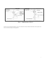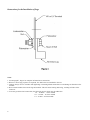
1
MTE Corporation
DRIVE ISOLATION
TRANSFORMER
TYPE: T
USER MANUAL
PART NO. INSTR - 017
REL. 031112
Instructions for the Safe Handling, Installation, Operation
and Maintenance of Ventilated Dry-Type Transformers
Table of Contents
Paragraph
Page
General ........................................................................................................................................................1 ...................... 2
Inspection upon Receipt ...........................................................................................................................2 ....................... 2
Handling .....................................................................................................................................................3 .....................2-3
Storage ........................................................................................................................................................4 ...................... 3
Application .................................................................................................................................................5 ....................... 3
Installation ..................................................................................................................................................6 ...................... 3
Accessibility ................................................................................................................................... 6.1 ..................... 3
Ventilation ...................................................................................................................................... 6.2 ..................... 3
Sound .............................................................................................................................................. 6.3 .................... 3
Environmental Conditions ............................................................................................................ 6.4 ..................... 4
Outdoor Installation ...................................................................................................................... 6.5 ..................... 4
Connections ...............................................................................................................................................7 ....................... 4
Lighting Tap Applications ............................................................................................................ 7.1 ..................... 4
Grounding ...................................................................................................................................... 7.2 ..................... 4
Before Energizing .....................................................................................................................................8 ....................... 4
Operation ....................................................................................................................................................9 .....................4-5
Maintenance .............................................................................................................................................. 10 ..................... 5
Drying ......................................................................................................................................................... 11 ...................... 5
IMPORTANT: The information contained
herein is general in nature and is not intended
for specific application purposes nor is it
intended as a training manual for
unqualified personnel. It does not relieve
the user of responsibility to use sound
practices in application, installation,
operation and
maintenance
of
the
equipment purchased or in personnel
safety precautions. Should a conflict arise
between the general information contained
in this publication and the contents of drawings
or supplementary material or both, the latter
shall take precedence.
1. General
2. Inspection Upon Receipt
The successful and safe operation of dry-type transformers
is dependent upon proper handling, installation, and
maintenance. Neglecting certain fundamental installation
and maintenance requirements may lead to personal
injury and the failure and loss of the transformer as well
as damage to other property.
Immediately upon receipt of the shipment, identify all
units and check them against the shipping list. Make a
visual examination to detect any damage which may have
been incurred during transit. If any damage is discovered,
file a claim immediately with the carrier and send notice of
the extent of damage to the local sales office, giving
complete identification, carrier's name and railroad car
number if the shipment was made by rail.
The information will enable the company to supply
necessary data in support of claim.
WARNING: DANGER! There is a hazard of
electric shock or burn whenever working in
or around electrical equipment. Power must
be off before working inside a transformer.
Each transformer is assembled and given complete tests at the
factory, after which it is inspected and packed for
shipment.
2
3. Handling
All transformers are bolted to a wooden skid for shipment.
All units can be handled with a forklift truck.
Transformers are provided with lifting eyes at the top of the
enclosure for two point lift (see Figure 1) or at the base
for four point lift or by taking off the cover and using the
lifting means on the transformer. The use of a spreader is
generally recommended. Units are not designed for
laying on their ends or sides. If it is necessary to handle
ventilated Dry-Type Transformers outdoors during
inclement weather, they should be thoroughly protected
against the entrance of moisture. CAUTION: Never
attempt to lift a transformer from points other than the
lifting eyes provided.
6.1 Accessibility
4. Storage
Any transformer which is not installed and energized
immediately should be stored in a clean dry space having a
uniform temperature to prevent condensation. Preferably, it
should be stored in a heated building having adequate air
circulation and protected from cement, plaster, paint, dirt
and water. The protective plastic wrapping should be left
in place during storage.
5. Application
Insulation systems are classified by industry standards in
accordance with the following rating system
Insulation Systems Classification
Ambient
40° C
40° C
40° C
40° C
+Winding Rise
55° C
80° C
115° C
150° C
CAUTION: Installation and maintenance should be
performed only by experienced and qualified personnel. No
attempt should ever be made to change the taps, or make
cable connections while the transformer is energized. To
maintain safe operating conditions, do not remove the panels
or cover while the transformer is in operation.
+Hot Spot
10° C
30° C
30° C
30° C
Temp.
=Class
105° C
150° C
185° C
220° C
These transformers are designed using a 220° C insulation
system, regardless of the requested temperature rise of the
transformer. Transformers with a standard 150° C winding
temperature rise operate at full load with a maximum 50°
C / 122° F temperature rise on the surface areas of the
enclosure. As an example, with a 40° C ambient, the
maximum measured enclosure surface temperature would
be 90° C / 194° F.
6. Installation
Dry-Type Transformers are for indoor use unless the
enclosure is specifically designed for outdoor weatherproof service. They are cooled by means of free circulation
of air, the maximum ambient temperature of which
should not exceed 40° C (104° F). Damage may result if
the air flow is restricted, or if the transformer is loaded
beyond its rated capacity.
Due to various building and room constructions, it is
recommended that applicable codes be followed. Factors
which should be kept in mind when locating DryType
Transformers are: personnel safety, accessibility,
ventilation, locations affecting sound level, and
environmental conditions. Installations should be made in
an area reasonably free from dust, moisture, chemical and
corrosive vapors or fumes. Dry-Type Transformers must be
installed in an upright position.
Dry-Type Transformers should be located in an area
where the transformer can be inspected at any time. The
wiring compartment should be easily accessible at all
times. It is a requirement of the National Electrical Code
that sufficient access and working space shall be
provided and maintained about all electrical equipment to
permit the ready and safe operation and maintenance of such
equipment. Refer to the requirements of the NEC for the
particular installation involved. The working space
required by this standard should not be used as a passageway
or for storage. When normally enclosed live parts are
exposed for inspection or servicing, the working space, if
adjacent to a passageway or general open space where
other work is carried on, should be guarded.
6.2 Ventilation
Adequate ventilation is essential for the proper cooling of
Dry-Type Transformers and clean air is desirable.
Filtered air may reduce maintenance if a location presents
a particular problem.
The ventilating screens and openings in the transformers are
designed to provide adequate ventilation for the
transformer and should not be restricted in any way.
Transformers rated through 51 KVA should be located at
least 4 inches away from walls or other obstructions to
allow free circulation of air through the ventilation
openings. For units above 51 KVA, spacing should be a
minimum of 6 inches. If the transformer is located in a
small room, ventilation should be provided to maintain an
average of 30° C (86° F) ambient not to exceed 40° C
(104° F) in any 24-hour period.
6.3 Sound
Audible sound may be a factor, and consideration should be
given to the specific location and method of installation of
the transformer keeping in mind the following
suggestions:
• Mount the transformer away from corners of walls
or ceilings.
• Provide flexible conduit to make the connection to
the transformer.
• Use sound absorbing material on the walls and
ceiling.
• Locate the transformer as far as practical from
areas where high sound levels are undesirable.
3
6.4 Environmental Conditions
7.1 Lighting Tap Applications
Ventilated Dry-Type Transformers are normally designed for
installation in indoors applications only. They may be
installed outdoors if they are of outdoor construction..
Transformers should be installed in locations where the
ambient atmosphere is free from unusual chemical fumes
or dust.
Most transformers with 240 volt delta secondaries have a
120 volt single-phase lighting tap. The maximum singlephase 120 volt load should not exceed 10% of the threephase KVA rating. The load should also be balanced at
5% maximum between terminals X1 to X4 and 5%
between terminals X2 to X4. The three-phase KVA must
also be reduced by 30% of the nameplate rating.
6.5 Outdoor Installation
7.2 Grounding
The same care must be taken when selecting a location for
outdoor Dry-Type Transformers.
Walls may be built around the transformer if proper care is
taken to allow sufficient air flow. It is recommended that
a suitable concrete pad with adequate drainage be used for
the outdoor location. Pad should be approximately 4" above
ground level. The hole plugs supplied with some outdoor
units must be in place in each end of the unit to prevent
moisture from entering the enclosure (Figure 1).
All core and coil structures have a flexible ground
connection to the enclosure which ensures that all dead
metal parts have the same potential. The transformer
enclosure should be solidly grounded so that no danger will
exist for operating or maintenance personnel. A
transformer ground stud or ground bus is provided for the
customer's ground connections. The grounding conductor
for a transformer should have a current-carrying capacity
in accordance with the National Electrical Code.
CAUTION: Transformers are not tamper proof. The
location of the transformer must be away from children and
all unauthorized personnel. Failure to do so may result
in serious injury.
8. Before Energizing
7. Connections
All cable entrances should be into the terminal compartment
located in the lower transformer enclosure. When making
cable connections or changing taps, always use two
wrenches when tightening or loosening bolted
connections to prevent distortion or damage. The
terminal connections are either bare aluminum, tin plated
aluminum or copper. The aluminum surfaces are furnished
with a protective coating to prevent oxidation. The unused
tap connections are also furnished with a protective coating.
This coating should remain intact until these connection
points are needed.
CAUTION: Make only those connections shown on
the nameplate or connection diagram. Before energizing,
check all tap jumpers for proper locations, and all bolted
connections for tightness.
If it is necessary to change taps or assemble a lug
to a connection point, gently scrape coating from
new connection surface using a sharp knife. Apply
a light coating of grease from the tap jumper pad
to the scraped surface and tighten connection using
two wrenches as described above. Refer to Figure
3, Page 8 for instructions for the installation of
cable lugs. Care must be taken to place all leads to
the same load, or from the supply source through
one knockout so that no part of the transformer
case is positioned between such leads.
NOTE: After installation of connectors and cabling, a
minimum of 1" clearance must be maintained from
energized parts to all case parts.
4
Before energizing the transformer, loosen or remove all
shipping hardware, and store for future use. If it is
desired to change location of the transformer at a future
date, reinstall all shipping hardware as shown in Figure 1.
If shipping hardware is left in place, excessive enclosure
vibration will increase the sound level.
Check all tap jumpers for proper locations, and all bolted
connections for tightness, using two wrenches as
described in Section 7.
After installation is completed, remove any debris from
the bottom of the wiring compartment. Securely tighten
all screws which hold the panels and covers in place to
eliminate possible vibration of these parts.
9. Operation
To maintain safe operating conditions do not remove
panels or covers over openings in the enclosure while the
transformer is energized.
CAUTION: Never attempt to change taps or connections
unless the transformer is de-energized and all windings
grounded.
For all relatively clean and dry indoor installations, the
transformer will operate satisfactorily under normal
conditions of energization and load. There is no concern over
the transformer's ability to retain its electrical strength
during reasonable periods of shut down. Under severe
conditions and extended shutdown periods condensation
may form and ultimately be absorbed into the insulation. If
such a situation occurs, the transformer should be
inspected for visible signs of moisture before reenergizing. The transformer should be dried as specified
Section 11, "Drying" if moisture is visible. Transformers
should not be overloaded for long periods of time
The resulting temperatures can cause insulation deterioration
and transformer failure. If at any time evidence of overheating
is noticed, external fans (fans blowing on the outside of the
enclosure or louvers) must not be directed toward the
transformer. This practice can result in mis-directed air flow
which can retard or stop normal convection through the
transformer coil. As a result the transformer will further
overheat and failure may result in a short period of time.
10. Maintenance
Under normal environments and operating conditions,
Dry-Type Transformers are virtually maintenance free.
However, they do require occasional external cleaning,
repainting, internal cleaning, painting, and periodic care
and inspection. Where periodic inspection of any kind
cannot be made, it should be recognized that the life of
the transformer may be affected. The frequency of
inspection will depend on the atmospheric and/or
environmental conditions at a given transformer
installation or location. A transformer may operate
satisfactorily for many years without attention but, under
unusual service conditions, maintenance may be required
in a matter of months.
A continuously energized transformer needs periodic
maintenance only to remove accumulations of dust and
dirt from cooling ducts and other surfaces. Large
accumulations may reduce cooling efficiency and lead
to overheating. The frequency of cleaning will depend
on the environment in which the transformer is located.
Cleaning is recommended at least once a year in relatively
clean installations and at more frequent intervals in
more heavily contaminated atmospheres. Transformers
which are de-energized for periods of time generally
require more frequent maintenance to insure removal of
contamination. Accumulation of dirt on insulating
surfaces becomes a hazard when a considerable amount of
moisture is absorbed. It is always advisable to clean any
transformer suspected of having been contaminated with
dirt and moisture. Vacuuming is the recommended
method for cleaning. Special attention should be given
to cooling ducts within the windings. Low pressure, dry
air can be used if care is taken to avoid driving the
contamination deeper into insulations. When it is known
that a transformer has been exposed to severe
conditions of moisture, it should be cleaned and dried
before energization.
Maintenance must be done with the transformer in a
de-energized condition. This would include such things
as tap changing, internal inspection and cleaning, locating
causes of faulty performance, replacing parts, etc.
Corrective maintenance should be performed by a
person who is familiar with the construction and
operation of the apparatus and the hazards involved. In
conducting corrective maintenance, such a person
should.:
• Be sure that the transformer is disconnected
from all electric power sources before
servicing.
• After power has been disconnected from the
transformer, attach ground leads or their
equivalent to the input and output terminations
of the transformer. Such grounding may be
unnecessary in the case of transformers that can
be visibly isolated from energized conductors by
other disconnecting means.
• Inspect terminals for alignment, tightness,
pressure, burns, or corrosion. Consult factory to
replace pitted or badly burned lugs.
• Inspect air ducts for the accumulation of dust and
foreign substances; vacuum any accumulation.
• See that bolts, nuts, washers, pins, terminal
connectors, including ground connection, are in
place and in good condition.
11. Drying
Moisture is detrimental to most insulation systems. It is
advisable to dry out any transformer which has been
exposed for long periods of high humidity. Whenever
moisture is visible on insulation surfaces, the unit must be
dried before being energized.
Drying may be accomplished by application of hot air,
radiant heat or internal heat. Heated air should rise
through the windings. Heaters should be located
beneath the windings and elements should not be
allowed to come in contact with the transformers. Heat
should be applied on both front and rear of the transformer.
The capacity of strip or space heaters required can
generally be taken to be one-half watt for each pound of
transformer nameplate weight. The application of heat
should be maintained for a minimum of twenty-four hours
after moisture is no longer visible.
Transformers may be subjected to flooding, direct rain or
similar applications of water. In such cases, normal
drying techniques may not be adequate and the factory
should be consulted. Unfortunately, insulation
resistance tests of the type used on liquid filled
transformers are of little value on Dry-Type
Transformers. The nature of insulation used in Dry-Type
Transformers is such that the megger and power factor
readings are not reliable and may be misleading.
5
Shipping and Handling Notes:
1. Units designed to be lifted and handled by fork truck.
2. Units are shipped with skids to be removed at installation.
3. Remove shipping hardware at installation (See Figure 3).
.
6
Figure 3 - Shipping Hardware Removal
NOTE: On units with shipping hardware, only remove the hardware used to attach the transformer to the side panel. Also
take off removable lifting eyes when applicable.
7
Instructions for the Installation of Lugs
Notes:
1. See Paragraph 7, Page 4 for complete information on connections.
2. When 2 or more lugs per phase are required, face half to the front and half to the rear.
3. Caution: Always use two wrenches when tightening or loosening bolted connections to avoid damage or distortion to the
terminal.
4. Do not install washers between the lug and terminal. This will cause heating and arcing, resulting in failure of the
connector.
5. To ensure good electrical connections, the following torque values must be adhered to:
1/4 - 20 Bolt - 7 Foot Pounds
3/8 - 16 Bolt - 20 Foot Pounds
1/2 - 13 Bolt - 30 Foot Pounds
8