1
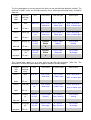
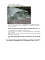
Setting up operation RQ-30, RQ-30a
firmware version 1_5x, RQCommander 2.0.X.X, document version R2
Discharge Measurement System
Guideline to first settings
Edition May. 2012
All rights reserved.
Contents
1.
INTRODUCTION.................................................................................................................................................... 1
2.
REQUIRED EQUIPMENT .................................................................................................................................... 2
3.
USB-NANO-485 INSTALLATION ........................................................................................................................ 2
4.
RQCOMMANDER INSTALLATION .................................................................................................................. 3
5.
CONNECTING RQ-30 AND PC............................................................................................................................ 3
6.
SETUP RQ-30 .......................................................................................................................................................... 4
6.1.
6.2.
6.3.
6.4.
GET ACTUAL PARAMETERS FROM RQ-30 ......................................................................................................... 4
UNITS AND DECIMALS ...................................................................................................................................... 4
FROM PROFILE TO RQ-30 DISCHARGE TABLE .................................................................................................. 5
RQ-30A ANALOG OUTPUT SETUP .................................................................................................................... 6
7.
RQ-30 TESTS IN OFFICE ..................................................................................................................................... 8
8.
HELPFUL SUPPORT INFORMATION............................................................................................................... 8
1. Introduction
This guide is meant for the first usage of an RQ-30 system right out of the box. The RQ-30 needs
some site specific information especially to calculate the discharge. There are also many costumer
specific setup possibilities implemented, which should be set soon as possible.
To make sure your RQ-30 is delivering the information you will need, we recommend, to do the first
settings in the office. This guide leads you through the PC installation of delivered RQ-30
parametrising tools and the most important customer settings. It is helpful to get familiar with the
technics and needed information before mounting the RQ-30 system on the site:
o
The designed measurement site is suitable (see RQ-30 user manual chapter 4.1).
o
To get a valid discharge from the RQ-30 you have to fill out its discharge table. RQCommander
can build this table automatically, but you have to put in the cross-section profile of the river or
channel. Before you can setup the RQ-30 completely, you must get the profile data of your
measuring site (see RQ-30 user manual chapter 3.3 and chapter 5.1).
o
You have think about your level (gage) measuring coordinate system called W. (Character “W”
represents the chosen Water level coordinate system) and where your cross-section profile is
placed in this system. Also the mounting height of the RQ-30 have to be placed in this
coordinate system by doing a level adjustment or doing a direct setting of RQ-30 level (= WRQ
parameter) (see RQ-30 user manual chapter 5.2).
o
You have to choose your output units, so the data collecting system (e.g. a data logger) can be
set up as well. Some of these settings are site size dependant, so you should have an idea of
maximum discharge of the river or channel.
o
In advance you can estimate the minimal and maximal water level of the site.
This guide is meant for averaged PC users and all guide parts are written in a common explanation
form with intent, because some windows dialogues can differ from windows to windows version.
2. Required Equipment
To check out the delivered RQ-30 equipment in the office, you will need some additional things.
This is guide is written for a delivered Sommer main-cable. If you build the cable by your own (see
RQ-30 user manual chapter 2.4) check the wiring by your own specifications.
Total equipment list:
o
RQ-30 (delivered)
o
Sommer main-cable (delivered)
o
9-24 Volt power source with capability of at least 200 mA current
o
Maybe some wirings an clips to do the power connection
o
USB-nano-485 converter and an USB extension cable (delivered)
o
A PC or Notebook with a free USB port and a Windows operating system (Win XP or later) with
administration rights and a CD-ROM drive
o
A installation CD of RQCommander and in the case of no internet-connection the installing CD
of the USB-nano-485 converter (delivered)
o
A small screwdriver to connect the USB-nano-485 converter to the Sommer main-cable.
o
A medium Phillips screwdriver to open up the body housing of the RQ-30 to plug in the
Sommer main-cable.
3. USB-nano-485 Installation
USB-nano-485 converter installation consists of two separately drivers. First driver to install is the
“USB-nano-485” USB Controller and the second one is the “USB Serial port” driver. A detailed
explanation what to do follows (afterwards USB-nano-485 converter is shortly called converter):
1.
Put in the converter in one USB slot of your PC. In most cases Windows detects a new USB
device and starts the driver installation which is called "USB-nano-485" automatically. If
windows doesn't, please make sure you have administration rights and then have a look at:
”Start -> Control Panel (-> System and Security) -> System -> Device Manager” and look there
under "Other Devices" for " USB-nano-485" and start the driver installation from there.
2.
If you have an opened "internet connection" let windows search there for the most actual
driver, when you will be asked for by the installation dialogue. This works fine in some cases,
but if windows can't find a matching driver, start the installation dialogue once again until the
point where it asks you “Browse my computer for driver software” and click on this option now.
Please insert the Installing CD for the converter (CTI CD) and give in the CD-ROM path. In
most cases the root directory-path of the CD-ROM is deep enough and windows find the
correct driver in the subdirectories by its own (check mark option).
3.
At the next step in the dialogue, Windows will tell you that the driver has no valid digital
signature. You have to accept this circumstance before you can install the driver. Then let
windows work, to do the installation and close the dialogue when you will be prompted for.
4.
The next step in the driver installation is that automatically starts the installation dialogue once
again, that seems to be strange to many user, but if you carefully read the windows messages
you will see, that a second driver should be installed which is called "USB serial port". From
now it is completely the same process as before at the "USB-Nano-485" installation.
5.
When all dialoges finished a new “USB serial port” COM X is being released. Once again in
the “Device Manager” (Start -> Control Panel (-> System and Security) -> System -> Device
Manager) you can find a new COM under "Ports (COM & LPT)". The most important thing to
know for the next chapters of this guide is the COM number X. If you are not sure which USB
serial port COM is the one of the converter, detach and attach the converter from the USB slot
and look which COM number disappears and reappears again in the "Ports (COM & LPT)" list.
6.
Close all opened windows an notice the COM number X of the converter. The installation
process of the converter is finished and doesn’t have to be done again in later sessions on this
computer, except if you have changed the converter by another one, but in this case windows
does the installation most times automatically.
Note: It is not recommended to change the converters dip switch settings at all.
4. RQCommander Installation
RQCommander software is easy to install. First insert Installation CD (Sommer CD) and start the
Setup.exe program out of the “CD_RQCommander_V2.0.X.X” folder.
The dialogue process will guide you through the installation.
The easiest and the recommended way is to select "standard" installation and the "default"
installation path "C:\DME\RQCommander".
Note: Due to restricted admission rights it is important not to choose the "Program files" folder for
installation path.
Note: If you want to update your RQCommander installation please use always "repair" option.
5. Connecting RQ-30 and PC
What has to be done, step by step:
1. Open up the 4 side bottom screws of the RQ-30 and lift its cover to plug in the Sommer maincable at the RQ-30. Make sure that your connection is good by listening and feeling of the
engaging noise and feel of the bayonet nut connector.
2. Connect USB-Nano-485 converter to the Sommer main-cable by using the small clamps on the
converter and the small (slot) screw driver:
o
The yellow wire (RS 485 A wire) must be connected to the A clamp.
o
The grey wire (RS 485 B wire) must be connected to the B clamp.
Note: If the RS-485 bus-system have another devices planned (for e.g. a data logger)
separate them from the bus-wiring while parametrisation. Otherwise this could lead to
many crash situations by double mastering of the bus-system.
3. Prepare power supply to be connected with RQ-30:
o
The brown wire (+ wire) must be connected to the + side of the power supply.
o
The white wire (- wire) must be connected to the - side of the power supply.
ATTENTION: Make sure that there are no possibilities for electrical shortcuts in the
power supply wiring!
4. Switch off the power supply and start RQ-commander software.
5. Select the "Parameter" Tab and click in the "connection" so it becomes a blue frame.
6. Choose at the Com Port field your COM X number of the USB-Nano-485 converter (see
Chapter 3, Point 5-6). Select baudrate 9600, because it is the RQ-30s default baudrate. The
check-marks in the connection field must be cleared.
7. Click on terminal window, so it becomes a blue frame and then click on the most left button
which means "connect". The terminal should go online and shows the COM number and the
baudrate in the terminal frame headline. When an error message does occur, check if you have
the correct COM number X (see chapter 3 of this guide).
8. Switch on RQ-30s power supply and wait 5 seconds. Now the boot message of the RQ-30
should appear at the black terminal window. If it doesn't, something is wrong with the RQ-30 or
its wiring. Also the settings in connection frame could be wrong. Please check voltage and the
correct polarisation of the power supply.
9. Have a look at the left screen side. There is a button "Load Schema". For the first usage of a
new RQ-30 system you have to “Load Schema” first. Feel free to push it and confirm its safety
retrieval. You will see a new connection window with a progress bar and a lot of communication
in the terminal window. When this process is finished, the RQ-30 is ready for first
parametrisation. If you don’t have updated your RQ-30 version, you don’t have to do this
procedure once again, cause the RQCommander software now know all RQ-30s parameter
names and ranges, and stores this information in a schema locally.
10. We recommend to close the RQCommander software now, because then the next chapter
shows - as a first example - what you normally doing with the RQCommander software.
6. Setup RQ-30
6.1. Get actual Parameters from RQ-30
First you have to open a new RQ-Commander session by starting the “RQCommander.exe” file.
The most important thing for now to do is to connect with RQ-30 to get its actual parametrisation:
1) Check your wiring and the power supply (see chapter 5).
2) Select "parameters" tab. Check the right COM number (see chapter 3) and its baudrate in
the connection window (see chapter 5).
3) Push button "Load Parameter" on the left side of the screen to let the RQCommander fill the
local stored "Schema" with the actual parameters of the RQ-30. Wait until the whole
process is finished. Note: The RQ-30 is normal measurement mode while loading
parameter. This could lead to some data crash situations on RS-485 because the RQ-30
pushes out the measurement data from time to time. The loading process of RQ-30 is doing
its own recovery in these situations, so don’t care about some strange looking characters in
the terminal window or some red written lines in the progress bar window.
6.2. Units and Decimals
If all parameters are loaded, the RQ-Commander shows in the middle of the screen in the window
"Sensor parameters" the filled out actual parameters of the RQ-30. You can have a look at the
actual parameters set - but please - before you do any customizing, set your own designed set of
units and decimals! This is very helpful, because many parameters are dependant of these
settings. You can avoid a lot of work of reparametrisation, if you choose your units first. To do this:
1) Click on the "+" sign before "Technics", then the "Technics" sub menu is drop down. Then
click on "+" sign before "Units and decimals" and you will see the actual default unit and
decimal settings of the RQ-30. Select your combination of your preferred units and select
"well balanced" decimals. Dependant of your measuring site the decimals should not to be
set to big, cause the maximum amount of decimal digits of a output value are 7. For
example: A site with a maximal discharge of 9999 cubic ft per second, should not have
more than 3 decimals for the discharge, otherwise the value could not be transferred in
especially high water situations. Note: Most times the AUX measurement is not in use, than
the setting of its units is not important. Per default the AUX is set for a IR temperature
measurement in degrees Celsius.
2) All changed parameters are marked with light red colour and if your selection is ok, you
could send them to the RQ-30 by pushing the button "Send Modified Parameters".
Afterwards all parameters will be sent in a stack to the RQ-30 and if the process finishes
correctly, all light red marks will be removed.
6.3. From Profile to RQ-30 Discharge Table
If you already know your cross-section profile and your favour level coordinate system (W), it is
time to change the RQCommanders screen to “profile” tab. In this guideline is not enough space to
describe the process to be done at this tab, but in the RQ-30s user manual the big chapter 5.1
describing this process in detail. This guide just describes how you will send your profile based
“RQ-30 List” to the RQ-30. If you have done all your settings in the profile tab screen and have
good looking RQ-30 List, then following steps transfer it from the RQCommander to the RQ-30
itself:
1) Go to “Parameter” tab again.
2) Push button “Send Discharge Table” on the left side of the screen and wait for the job to be
done.
3) When finished push “Load Parameter” button, to check out the new written settings on the RQ30.
4) Click on all "-" signs before in the “Sensor Parameter window” to get an overview of the RQ30’s
main menu, then click on “+” sign before “Discharge table (Q)", so you will se the actual written
discharge table. Now you can compare the values in the RQ-30 with them in the “RQ-30 List”
on the profile tab screen. Note: It is not necessary to use the same units in the profile settings
as they are on the RQ-30, RQCommander automatically adapting the meaning of the values.
6.4. RQ-30a Analog Output Setup
Only if you are using a RQ-30a with 4-20 mA analog outputs (IOUT) this part of setup the RQ-30
concerns to you. All analogue output settings should be checked by the user, because their
settings are also strongly combined with the measuring site. The usage of them is always technical
stuff and it is not just part of the RQ-30, also the 4-20 mA input system has to be adjusted in a
compatible way. Here is a step by step guideline for set up the IOUTs correctly:
1) Click on the "+" sign before "Technics" if it is not already opened, then click on "+" sign before
"4-20mA outputs". Now all possible 4-20 mA output parameters are drop down.
2) Then choose your site dependant settings. Note: It is not too important to select the ranges
and offsets absolutely closely to site. In most cases it is better to do it in a balanced way,
especially if you have more than one RQ-30 and want to have the same settings for all sites. In
this case it is best to check out the settings with the biggest site.
o
IOUT1 (AUX): In most cases IOUT1 settings are not relevant cause the input is has been
turned off. Otherwise the setting is strongly dependant of what you are measuring. Per
default it is set for a IR temperature measurement.
o
IOUT2: (level): These 2 settings (4 mA value and 4-20 mA span) are strongly dependant of
the chosen level (gage) measurement system (W). Note: Please don’t use the 4 mA value
for level (W) offset adjustments! If you using relative level systems, which values are always
positive, use for e.g. 0 ft for "4mA value". The "4-20 mA span" could be set to the near of
the maximum level of the site. (E.G. If maximum level is 37.1 ft, a good value for the "4-20
mA span" is 50 ft). If you are using absolute level measurement systems (maybe based on
definitive sea-levels) and you want to use one offset value for all your sites and your lowest
measurable level of the lowest site is placed at 365,39 feet, use for e.g. 360 ft for the
"IOUT2 level, 4mA value" for all the sites. At 4-20mA outputs it is important to keep the
span relative closely to maximum level change, so probably in case of the example above
you will not using a "IOUT2 level, 4-20 mA span” of 420 ft to allow a 4 mA value offset of 0.
This setting would lead to an extraordinary loss of resolution at the 4-20mA output. So a
good compromise would be 360 ft for the "4mA value" and 60 feet for the "4-20 mA span",
so you can use the same settings for all sites between 360 and 420 ft minimum to
maximum absolute level.
o
IOUT3 (velocity): The "4 mA value" output of the velocity is always 0 (except tidal sites) and
the 4-20 mA span = "IOUT3, max velocity" could be set closely to maximal estimated speed
of the river. To keep it easy, use a straight number as for e.g. 20 ft/s.
o
IOUT4 (discharge): Here applies absolutely the same as at the IOUT3 (velocity), but the
"IOUT4, max. discharge" value can vary in a wide range from site to site. It could be not
feasible to use the same settings in more than one site, if they are differ too much in the
max. discharge. If you don't know the maximal discharge of the site, please read chapter
5.1.6 of the RQ-30 user manual.
3) All changed parameters in the RQCommander are marked with light red colour and if your
selection is ok, you could send them to the RQ-30 by pushing the button "Send Modified
Parameters". Afterwards all parameters will be sent in a stack to the RQ-30 and if the process
finishes correctly, all light red marks will be removed.
4) The next step is not for RQ-30 itself. It is for parametrising 4-20 mA input system, because you
will need this information there. Please fill out the values of your settings in one of the following
table files to make sure all information for parametrising a 4-20mA input system is complete.
The first table applies to a measurement site with just one possible flow direction (no tide). The
blue text in tables shows the RQ-30 parameter name, whose parametrised values should be
filled out:
Output
/wire
color
Physical
meaning /
entry
Unit
4 mA value
4-20 mA span
20 mA value
IOUT1
AUX
AUX unit
IOUT1 AUX,
4mA value
IOUT1 AUX, 420mA span
..AUX, 4mA value +
..AUX, 4-20mA span
black
Fill out >
IOUT2
Level (W)
Level (W)
unit
IOUT2 level,
4mA value
IOUT2 level, 420mA span
..level, 4mA value +
..level, 4-20mA span
violet
Fill out >
IOUT3
Velocity (v)
Velocity
(v) unit
Fixed at
RQ-30
IOUT3, Max.
velocity
IOUT3, Max.
velocity
blue/red
Fill out >
IOUT4
Discharge
(Q)
IOUT4, Max.
discharge
IOUT4, Max.
discharge
grey/pink
Fill out >
0
Discharge
(Q) unit
Fixed at
RQ-30
0
The second table applies to a system with two possible flow directions (tidal site). The
differences are due to the possibility of negative velocities and discharges:
Output
/wire
color
physical
meaning /
entry
Unit
4 mA value
4-20 mA span
20 mA value
IOUT1
AUX
AUX unit
IOUT1 AUX,
4mA value
IOUT1 AUX,
4-20mA span
..AUX, 4mA value +
Level (W)
unit
IOUT2 level,
4mA value
IOUT2 level,
4-20mA span
Velocity
(v) unit
- (IOUT3, Max.
velocity)
2 * (IOUT3,
Max. velocity)
IOUT3, Max.
velocity
- (IOUT4, Max.
discharge)
2 * (IOUT4,
Max. dischar.)
IOUT4, Max.
discharge
black
Fill out >
IOUT2
Level (W)
violet
Fill out >
IOUT3
Velocity
(v)
blue/red
Fill out >
IOUT4
grey/pink
Discharge Discharge
(Q)
(Q) unit
Fill out >
..AUX, 4-20mA span
..level, 4mA value +
..level, 4-20mA span
7. RQ-30 Tests in Office
We don’t recommend to do measurement tests of the velocity radar and the level radar in the
office, because radar waves would be reflected, crooked and absorbed by the office walls and
its furniture many times and in an absolute unpredictable way. The internal inclination
measurement of the RQ-30 and its influence on the interpretation of the measured Doppler
frequencies makes it also difficult to get a correct distribution of moved test objects.
If you like, you could change screen tab of the RQCommander to “spectrum” and push the
“spectral mode” button to check out the RQ-30 sensibility for measuring moved objects, but
concern that the spectral distributions of these objects are mostly not typical for a river, so RQ30 software sometimes evaluate these spectral distributions as failure measurements.
Also level measurements sometimes work in the office, but you have to wait at least 60 seconds
after turn up the radar and you have to use are a good radar reflector as a metal plate in at least
1 m distance and perpendicular to the RQ-30. But if the test doesn’t work, it is not definitely the
failure of the RQ-30, it could be also a failure of the test setup.
8. Helpful Support Information
To give you an optimal support in case of troubles, we need possibly a lot of information of the
site.
1. At the end of all RQCommander sessions - when parametrising the RQ-30 - load the actual
parameter set of the RQ-30 (see chapter 6.1) and push “Save Parameter File” button to
save it. If you will use our support, we can do it much faster, when we can load this
parameter file here at company to have an overview what is going on there.
2. If you have completed your profile in the RQCommander (see chapter 6.3 in this guide or
chapter 5.1 in the RQ-30 user manual) please store your work. To do this, make sure your
actual screen is the profile tab screen and then go right up to the “file” menu of the
RQCommander. There should be a menu point which is called “Save Profile” (or press
CTRL-S). Click it and so you can work further later, if open the file once again. It is important
to know, that the profile data have much more information, than just the discharge table of
the RQ-30. For example, just the profile data file contains the whole geometry of the river
bed. For our support this information is also important too, so please, if you have any profile
data please send us this file as well.
3. Make some pictures of a site, especially from river itself and the position of the RQ-30. It is
also good to make a picture the rivers surface on the measuring spot. If the RQ-30 shows
sometimes strange data, most times it gives us and you a lot of interesting information,
when you go to the site and make the pictures right then when RQ-30 is not working well.
And if you will be there throw a small piece of wood in the river and try to estimate the
velocity of the rivers surface.
4. If you have any external information about the site and its specialities, please tell us. Helpful
for us could be some answers of these questions:
o
Are there another river mouths nearby the measuring site?
o
Does the RQ-30 looking river upward or downward?
o
Are there river power stations nearby?
o
Is there a lake or the sea nearby?
o
Are there any standing waves in the water?
This picture is just to have an idea what standing waves are and how big they can be.
o
What are you think about the wave surface on the river, do mean it is more or less than
3 mm (1/8 of an inch)?
o
Are there any moving objects nearby, especially in the extension region of the water
reflected radar spot (Trees, bushes, grass wobbling in the wind, railways, streets).
o
Is there any kind of a regularly ship movement on the river?
o
If the measuring site is very windy, is there a main wind direction or does direction
change very often?
o
Could there be any visible or sensible vibrations on the RQ-30 housing, caused by
traffic, wind or something else?
o
Is the RQ-30 mounted under the bridge or under a special roof? Are there any
possibilities of water down spouts in the radar cone (area between radar spot and radar
itself)?
5. If you have the possibility to log all measured data, so do this please. For the supporting
team especially the measured level, velocity and quality are very helpful. So if you have
troubles and you have some “timelines” of these values, please send us them as well.