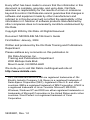
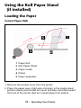
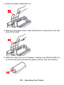
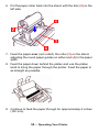
1
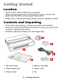
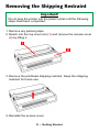
Every effort has been made to ensure that the information in this
document is complete, accurate, and up-to-date. Oki Data
assumes no responsibility for the results of errors or omissions
beyond its control. Oki Data also cannot guarantee that changes in
software and equipment made by other manufacturers and
referred to in this document will not affect the applicability of the
information in it. Mention of software products manufactured by
other companies does not necessarily constitute endorsement by
Oki Data.
Copyright 2004 by Oki Data. All Rights Reserved
Document: MICROLINE ML186 User’s Guide
First Edition: January, 2004
Written and produced by the Oki Data Training and Publications
Department.
Please address any comments on this publication to:
Oki Data Americas, Inc.
Training and Publications Department
2000 Bishops Gate Blvd.
Mount Laurel, NJ 08054-4620
We invite you to visit Oki Data's multilingual web site at:
http://www.okidata.com.
OKI, Oki Data and MICROLINE are registered trademarks of Oki
Electric Industry Company, Ltd. Epson is a registered trademark of
Seiko Epson Corporation (SEC), registered in the U.S. and other
countries. IBM is a registered trademark of IBM Corporation. LINUX is
a registered trademark of Linus Torvalds. Microsoft, MS-DOS,
Windows, Windows NT and DOS are either registered trademarks or
trademarks of Microsoft Corporation in the United States and/or other
countries. Word Perfect is a registered trademark of Corel
Corporation.
59358801, Rev. 1.0
Contents
Notes, Cautions, etc. . . . . . . . . . . . . . . . . . . . . . . . . . . . . . . . . . 4
Getting Started . . . . . . . . . . . . . . . . . . . . . . . . . . . . . . . . . . . . . . 5
Location . . . . . . . . . . . . . . . . . . . . . . . . . . . . . . . . . . . . . . . . . . 5
Contents and Unpacking . . . . . . . . . . . . . . . . . . . . . . . . . . . . . 5
Removing the Shipping Restraint . . . . . . . . . . . . . . . . . . . . . . . 6
Installing/Replacing the Ribbon Cartridge . . . . . . . . . . . . . . . . 7
Installing the Platen Knob . . . . . . . . . . . . . . . . . . . . . . . . . . . . 10
Adjusting the Head Gap . . . . . . . . . . . . . . . . . . . . . . . . . . . . . 11
Installing the Paper Separator . . . . . . . . . . . . . . . . . . . . . . . . 12
Setting Up Your Printer . . . . . . . . . . . . . . . . . . . . . . . . . . . . . . 13
Power Connection . . . . . . . . . . . . . . . . . . . . . . . . . . . . . . . . . 13
Loading Paper . . . . . . . . . . . . . . . . . . . . . . . . . . . . . . . . . . . . 14
Testing Your Printer . . . . . . . . . . . . . . . . . . . . . . . . . . . . . . . . 29
Computer Connections . . . . . . . . . . . . . . . . . . . . . . . . . . . . . . 30
Setting up the Printer to Work with Your Computer . . . . . . . . 35
Operating Your Printer. . . . . . . . . . . . . . . . . . . . . . . . . . . . . . . 39
Front Panel Operation . . . . . . . . . . . . . . . . . . . . . . . . . . . . . . 39
Setting Printer Defaults. . . . . . . . . . . . . . . . . . . . . . . . . . . . . . 42
Using the Pull Tractor Unit . . . . . . . . . . . . . . . . . . . . . . . . . . . 50
Using the Roll Paper Stand . . . . . . . . . . . . . . . . . . . . . . . . . . 53
Maintenance . . . . . . . . . . . . . . . . . . . . . . . . . . . . . . . . . . . . . . . 57
Replacing the Ribbon Cartridge . . . . . . . . . . . . . . . . . . . . . . . 57
Testing Your Printer . . . . . . . . . . . . . . . . . . . . . . . . . . . . . . . . 59
Cleaning the Housing . . . . . . . . . . . . . . . . . . . . . . . . . . . . . . . 61
Troubleshooting . . . . . . . . . . . . . . . . . . . . . . . . . . . . . . . . . . . . 63
General Information . . . . . . . . . . . . . . . . . . . . . . . . . . . . . . . . 63
Clearing Paper Jams . . . . . . . . . . . . . . . . . . . . . . . . . . . . . . . 69
Parts & Options . . . . . . . . . . . . . . . . . . . . . . . . . . . . . . . . . . . . 78
Replacement Parts . . . . . . . . . . . . . . . . . . . . . . . . . . . . . . . . . 78
Options . . . . . . . . . . . . . . . . . . . . . . . . . . . . . . . . . . . . . . . . . . 79
Specifications . . . . . . . . . . . . . . . . . . . . . . . . . . . . . . . . . . . . . . 80
Index . . . . . . . . . . . . . . . . . . . . . . . . . . . . . . . . . . . . . . . . . . . . . 84
3
Notes, Cautions, etc.
Note
A note appears like this. It provides additional
information which helps you to use and understand
the product.
Important
An important message appears like this. It provides
supplemental information which can prevent potential
problems.
CAUTION!
A caution message appears like this. It provides
information which, if ignored, can result in equipment
malfunction or damage.
WARNING!
A warning message appears like this. It provides
information which, if ignored, can result in the risk of
personal injury.
4 • Notes, Cautions, etc.
Getting Started
Location
• Select a firm, solid surface for your printer.
• Allow enough space around the printer to easily access the
platen knob and the various paper feed paths.
• Make sure a suitable grounded power outlet is available nearby.
Contents and Unpacking
• If any items are missing, contact your dealer immediately.
• Keep your packing materials and carton in case you ever need
to ship or transport the printer.
• Interface cables and paper are sold separately.
.
1 ML186 Printer
4 Ribbon Cartridge
2 Paper Separator
5 Power Cord
3 Platen Knob
6 CD
5 • Getting Started
Removing the Shipping Restraint
Important!
Do not plug the printer into the power outlet until the following
steps have been completed.
1. Remove any packing tape.
2. Reach into the top cover slot (1) and remove the access cover
(2) by lifting it.
3. Remove the printhead shipping restraint. Keep the shipping
restraint for future use.
4. Reinstall the access cover.
6 • Getting Started
Installing/Replacing the Ribbon
Cartridge
Use only genuine Oki Data ribbon cartridges.
When replacing a ribbon cartridge, make sure you have the correct
replacement ribbon for your printer. The wrong ribbon will not print
when installed in your printer.
Important
• Leave unused ribbon cartridges in their packaging until you
are ready to install them.
• Careful! The ribbon ink can cause permanent stains.
• Ribbon ink on skin or clothing can usually be removed with
soap and water.
1. Make sure the printer is turned off!
WARNING!
If the printer has been recently used, the printhead may be
HOT!
7 • Getting Started
2. Remove the access cover and center the printhead.
3. If you are replacing the ribbon cartridge, remove the used one:
Important
Do not remove the ribbon shield (1) from the new ribbon!
8 • Getting Started
4. Unpack the ribbon cartridge and install it on the printhead.
Note
If the ribbon won’t load easily, turn the take- up knob
slightly until the x-shaped notch on the bottom of the
ribbon cartridge aligns with the x-shaped insert on
the ribbon plate.
5. Press gently on the ribbon cartridge until you feel it click into
place.
9 • Getting Started
6. Turn the take-up knob (1) in the direction of the molded arrow to
take up any ribbon slack.
7. Replace the access cover.
Installing the Platen Knob
Align the notch (1) with the pin on the platen shaft and push it firmly
into place.
10 • Getting Started
Adjusting the Head Gap
The head gap is the distance between the printhead and the platen
roller. When you use envelopes or multipart forms, you need to
have a larger gap than when using plain paper. Use the
recommended head gap to ensure the best print quality and easy
paper feed
CAUTION!
Incorrect setting of the head gap can cause printhead
damage or ribbon jams. To avoid these problems set the
head gap for the type of media being used.
To adjust the head gap, move the colored lever (1) located to the
left of the ribbon cartridge to the correct position for the type of
media being used …
…as detailed in the following table:
Paper Type
Lever Position
Single Sheets, up to 20 lb. (75 g/m2)
1 or 2
Forms, 2-part [maximum thickness 0.28 mm]
2 or 3
Forms, 3-part [maximum thickness 0.28 mm]
3
Forms, 4-part [maximum thickness 0.28 mm]
3
11 • Getting Started
Installing the Paper Separator
The paper separator is used for printing on single sheets (no
carbons). With continuous forms paper, it is used to separate the
ingoing/outgoing paper to prevent paper jams.
1. Hold the paper separator with the spring-loaded feet down.
2. Place the tabs (1) on the paper separator in the two
corresponding slots ( ) on the printer.
3. Press down to release the paper separator onto the printer.
12 • Getting Started
Setting Up Your Printer
Power Connection
1. Make sure the printer is turned off.
2. Plug the power cord supplied with your printer into the back of
the printer.
Important
The outlet voltage must match the voltage marked on the
printer label.
3. Plug the other end of the power cord into an appropriate
grounded outlet.
13 • Setting Up Your Printer
Loading Paper
Three types of paper can be used with your printer:
• Continuous Forms Paper
(with or without the optional Pull Tractor)
• Single Sheets
• Roll Paper, using the optional Roll Paper Stand
Before You Start
1
2
3
4
5
Bail Arm Lever
Bail Arm
Paper Lever
Platen Knob
Head Gap Lever
14 • Setting Up Your Printer
Paper Lever Positions
= Single Sheet Feed
= Continuous Forms
Setting the Head Gap
Before you load paper, be sure to check the head gap lever setting
(see page 11).
Important
Do not plug the printer into the power outlet until the following
steps have been completed.
15 • Setting Up Your Printer
Loading Continuous Forms, Rear Feed
1. Make sure the printer is turned off.
2. Place the stack of continuous forms paper behind the printer.
3. Remove the access cover (1).
4. Pull the bail arm lever (2) — on the left side of the printer —
toward the front of the printer to lift the bail arm.
16 • Setting Up Your Printer
5. Move the paper lever (3) — on the right side of the printer —
toward the front of the printer to the continuous forms symbol.
6. Pull the lock levers (A) on the sprocket wheels at either end of
the platen forward, then adjust the sprocket wheels (B) so that
the sprockets align with the holes in the continuous forms you
are using.
7. Push the levers back to lock the sprocket wheels in position.
17 • Setting Up Your Printer
8. Insert the first sheet of paper between the paper separator
guides (5) and push it through the paper separator.
9. Place the paper between the sprocket feed guides (6) and feed
it behind the platen, gently positioning it so that its holes
engage the sprockets on the ends of the platen.
Note
Make sure you keep the lead edge of the paper
straight so that the sprockets engage the matching
pins on either side. Otherwise the paper will feed in
skewed and paper jams will occur.
18 • Setting Up Your Printer
10. Turn the platen knob (7) to advance the paper until it appears
in front of the platen, behind the bail arm.
Important
Check to be sure that the matching holes on either side are
engaging the sprockets (A). If they are not evenly matched
and the paper is skewed (B), back the paper out and try again!
19 • Setting Up Your Printer
11. Push back on the bail arm lever (2) to lower the bail arm.
12. Use the platen knob (7) to set the position of the paper to the
first printing line.
13. Replace the access cover, being sure to feed the edge of the
paper through the slot in the cover.
14. Turn the printer on.
20 • Setting Up Your Printer
Loading Continuous Forms, Bottom Feed
1. Make sure the printer is turned off.
2. Place the printer on a slotted printer stand, carefully aligning the
slot in the stand with the slot in the base of the printer.
3. Place a box of continuous forms paper on the stand, under the
printer.
4. Remove the access cover (1).
21 • Setting Up Your Printer
5. Pull the lock levers (A) on the sprocket wheels at either end of
the platen forward, then adjust the sprocket wheels (B) so that
the sprockets align with the holes in the continuous forms you
are using.
6. Push the levers back to lock the sprocket wheels in position.
7. Pull the bail arm lever (3) — on the left side of the printer —
toward the front of the printer to lift the bail arm.
8. Move the paper lever (4) — on the right side of the printer —
toward the front of the printer to the continuous forms symbol.
22 • Setting Up Your Printer
9. Insert the first sheet of continuous forms paper through the
opening in the printer stand and into the bottom of the printer,
gently feeding it into the printer until it appears in front of the
platen, and above the bail arm.
Important
Check to be sure that the matching holes on either side are
engaging the sprockets (A). If they are not evenly matched
and the paper is skewed (B), back the paper out and try again!
23 • Setting Up Your Printer
10. Move the bail arm lever (3) back to lower the bail arm.
11. Use the platen knob (5) to advance the paper to the first
printing line.
12. Replace the access cover, being sure to feed the edge of the
paper through the slot in the cover.
13. Turn the printer on.
24 • Setting Up Your Printer
Loading Single Sheets
Note
Before printing single sheets, you must remove the
Pull Tractor or Roll Paper Stand, if installed.
Your printer can accommodate single sheets up to 9.5 inches (241
mm) wide.
Note
In order to use paper wider than traditional letter size,
you must move the sprocket wheels to their
outermost positions so that the paper does not tear
on the sprockets. See the directions below.
1. Turn the printer on.
25 • Setting Up Your Printer
2. Move the paper lever (1) — on the right side of the printer —
toward the rear of the printer, to the single sheet symbol.
3. Ensure that the printer is off-line (press SELECT if necessary).
4. If you are using paper wider than 8.5 inches (216 mm), move
the sprocket wheels to their outermost position:
a. Remove the access cover.
b. Pull the lock levers (A) at either end forward and move the
sprocket wheels (B) as needed.
26 • Setting Up Your Printer
c. Push back on the levers to lock the sprocket wheels in
position.
5. Make sure the bail arm lever (2) is set to the rear of the printer
(closed position).
6. Raise the paper separator.
27 • Setting Up Your Printer
7. Adjust the sheet guide (3) on the paper separator to position the
left edge of the sheet, then insert a single sheet along the
guide until it reaches the pinch roller.
8. Pull the bail arm lever (2) toward the front of the printer.
The sheet of paper is drawn around the platen.
28 • Setting Up Your Printer
9. Push back the bail arm lever, ensuring that the paper has been
positioned correctly.
10.Press SELECT to place the printer on line.
Testing Your Printer
Your printer has a built-in test (self test) to make sure that it is set
up and working correctly.
1. Load continuous forms paper into the printer (see page 14, ff.).
2. Make sure the printer is turned off, then press and hold LINE
FEED while turning the printer on.
The test print begins.
3. To stop the test, press SELECT or turn the printer off.
Important
The top of each test printout contains information about your
printer. Be sure to have a copy of the printout handy if you
have to call for service.
29 • Setting Up Your Printer
Computer Connections
USB Connection
Notes
• For connection to a PC running Windows® 98 or
above, but not Windows 95 upgraded to Windows
98.
• The operation of a printer is not assured if a USB
compatible device is connected concurrently with
other USB-compatible machines.
• When connecting multiple printers of the same
type. they appear as *****, *****(2), *****(3), etc.
These numbers depend on the order of
connecting or turning on of each printer.
• USB is a “hot-pluggable” protocol. This means
that the printer and computer do not necessarily
have to be switched OFF.
• Interface cables are not supplied with your printer.
USB Cable Requirements
• USB 1.1 or higher
• Max. length 19.7 ft. (5 m)
• USB “B” series connector
30 • Setting Up Your Printer
1. Attach a suitable USB cable to the USB series “B” port on the
back of the printer.
2. Connect the other end of the cable to the computer.
3. If you turned the computer and printer off, turn them back on.
31 • Setting Up Your Printer
Parallel (LPT) Connection, IEEE-1284
Parallel/USB Model Only
Notes
• Interface cables are not supplied with your printer.
• It is not recommended that you connect parallel
and USB cables to the printer simultaneously.
Parallel Cable Requirements
• bi-directional
• max. length 6 ft. (1.8 m)
• 36-pin Centronics type connector
CAUTION!
Make sure the printer and computer are both turned OFF.
1. Turn both the computer and the printer OFF.
32 • Setting Up Your Printer
2. Attach a suitable bi-directional cable to the parallel connector
on the back of the printer and secure it with the wire loops.
3. Attach and secure the cable to your computer.
4. Turn the printer and computer back on.
Serial (COM) Connection, RS-232C
Serial/USB Model Only
Notes
• Interface cables are not supplied with your printer.
• It is not recommended that you connect serial and
USB cables to the printer simultaneously.
33 • Setting Up Your Printer
Serial Cable Requirements:
• Shielded RS-232C cable, UL and CSA approved
• Max. length 50 ft. (15 m)
• 25-pin serial connector.
CAUTION!
Make sure the printer and computer are both turned OFF.
1. Switch both the computer and the printer OFF.
2. Plug the cable into the serial port on the back of the printer and
tighten the screws.
3. Plug the cable into the computer and tighten the thumbscrews.
4. Turn the printer and computer back on.
34 • Setting Up Your Printer
Setting up the Printer to Work with
Your Computer
Note
• Settings made in your software application
normally override settings made in your printer
driver.
• Settings made in the printer driver normally
override settings made in the printer menu or via
the front panel.
Windows XP, 2000, Me, 98, 95, NT 4.0:
Install the Printer Driver
To print from a Windows-based system, install the printer driver
located in the Drivers folder on the CD supplied with your printer.
This driver incorporates commands which use the full capability of
the printer and automatically switches the printer to the correct
emulation regardless of which emulation is selected in the printer
menu.
1. Place the CD in your CD-ROM drive.
2. Click Start → Settings → Printers.
35 • Setting Up Your Printer
3. Click Add Printer.
The Add Printer Wizard appears.
4. Follow the on-screen instructions.
5. When you get to the window which asks you to select the
manufacturer and model of your printer, click Have Disk, then
browse to the appropriate directory on the CD and double click
the inf file:
Windows
Version
.inf File Location
XP
\Drivers\WinXP\English\Oemprint.inf
2000
\Drivers\Win2k\English\Oemprint.inf
98
\Drivers\Win98_Me\English\Oemsetup.inf
Me
\Drivers\Win98_Me\English\Oemsetup.inf
95B [OSR2]
\Drivers\Win95\English\Oemsetup.inf
NT 4.0
\Drivers\NT40\English\Printer.inf
6. Follow the on-screen instructions to finish loading the driver.
Non-Windows Systems:
Set the Emulation in the Printer Menu
Your printer has three emulations:
• IBM® 2480 — the factory default
• Epson® ESC/P2
• Oki Data® MICROLINE® Standard
If you are using a non-Windows system such as LINUX®, a
non-Windows application such as a DOS® program, or an older
application such as Word Perfect® 5.1, you need to make sure you
have the correct emulation selected in the printer menu (see
“Changing the Emulation Default in the Printer Menu” below). If
36 • Setting Up Your Printer
you have the wrong emulation selected, you will see strange
characters, incorrect fonts, etc.
Important
See your software documentation for information on how to
select an emulation in that application.
If you are directly replacing a MICROLINE ML184 Turbo or ML184
printer with the ML186, you must make sure that the printer menu
on your new ML186 is set to match the emulation being used for
the existing printer (see “Changing the Emulation Default in the
Printer Menu” below).
For Non-Windows Applications
Your printer is compatible with the emulations listed in the table
below and will function properly with software developed for them.
To make full use of the ML186 printer’s features, use the top entry
for the applicable emulation (e.g., IBM 2480). Entries further down
(e.g., IBM Graphics Printer Plus, IBM Graphics Printer) work well
with the printer, but do not provide full use of the printer’s
capabilities.
ML186 Emulation Mode
Compatible Printers/Drivers
IBM
IBM 2480
IBM Graphics Printer Plus
IBM Graphics Printer
Epson
Epson ESC/P2
Epson LX Plus
Epson LX
ML
Okidata MICROLINE Standard
37 • Setting Up Your Printer
Changing the Emulation Default in the
Printer Menu
The default for the emulation in the printer menu is IBM. If you wish
to change the menu default to another emulation:
1. Make sure continuous forms paper is loaded.
2. Turn the printer off.
3. Press and hold SELECT while turning the printer back on.
The printer enters the menu mode.
4. Press FORM FEED.
The first line of the menu prints, showing the emulation
engaged. For example:
Printer Control
Emulation Mode
IBM
5. Press TOF SET once or twice until the emulation you wish to
engage appears in the right-hand column.
Each time you press TOF SET, a new line prints and the setting
which appears in the last column changes. For example:
Printer Control
Printer Control
Emulation Mode
Emulation Mode
Epson
ML
6. Press PITCH and MODE together to save your setting and exit
the printer menu.
38 • Setting Up Your Printer
Operating Your Printer
Front Panel Operation
Front Panel Lights
LED
Status, Function
On = Printer is on line.
Off = Printer is off line.
Flashing = flashes with ALARM light to indicate a fault
has been detected.
On, SELECT light off = paper out.
On, SELECT light flashing = auto diagnostics have
detected an error.
Flashing, SELECT light on = printer has overheated.
Normal print operation will resume only after a
cooling period.
On = printer is turned on.
Off = printer is turned off.
The one lit indicates which character pitch —in
characters per inch (cpi)— is engaged.
39 • Operating Your Printer
LED
Status, Function
The one lit indicates which print mode is engaged:
NLQ = Near Letter Quality
UTILITY = Draft mode
HSD = High Speed Draft mode, or SSD (Super Speed
Draft) if 12 cpi is selected.
40 • Operating Your Printer
Front Panel Buttons
Button
Print Mode
Menu Mode
Held at Power Up
Advances the
paper one line
Scrolls through
the printer
menu groups.
Initiates printer
Self Test (see
page 59).
LINE FEED +
SELECT =
Initiates Rolling
ASCII test (see
page 60).
Advances the
paper to the
next top of form
or ejects single
sheet from the
printer.
Scrolls through
the items for
each menu
group.
FORM FEED +
SELECT = Places
Sets a new top of
form (TOF)
position.
Scrolls through
the settings for
each item
within a group.
Sets printer to 17
cpi.
Toggles the
printer on and
off line.
Prints list of
current menu
settings.
Places printer in
Menu Mode.
Selects the
character pitch
setting (cpi).
PITCH + MODE
Not applicable.
Sets print mode
(NLQ, Utility,
HSD).
PITCH + MODE
printer in hex
dump mode (see
page 60).
= save settings
and exit to print
mode.
= save settings
and exit to print
mode.
41 • Operating Your Printer
Not applicable.
Setting Printer Defaults
The printer has an internal menu containing a number of default
parameters which can be set to enable your printer to match the
parameters required by your computer.
Using the Menu Mode
Entering the Menu Mode
To enter the Menu Mode, press SELECT while turning on the
printer.
The 12 and UTILITY LEDs flash.
Printing a List of Current Menu Settings
With the printer in the Menu Mode, press SELECT to print the
complete menu.
The current default settings print out.
42 • Operating Your Printer
Sample Default Menu Printout
Parallel/USB Model
Printer Control
Emulation Mode
IBM
Font
Font
Font
Font
Font
Font
Print Mode
DRAFT Mode
Pitch
Proportional Spacing
Style
Size
Utility
SSD
10 CPI
No
Normal
Single
Symbol Sets
Symbol Sets
Symbol Sets
Symbol Sets
Character Set
Language Set
Zero Character
Code Page
Set I
American
Slashed
USA
Vertical Control
Vertical Control
Vertical Control
Line Spacing
Skip Over Perforation
Page Length
6 LPI
No
11 "
Set-Up
Graphics
Uni-directional
Set-Up
Receive Buffer Size
64K
Set-Up
Paper Out Override
No
Set-Up
Print Registration
0
||||||||||||||||||||| <----- |||||| --------> |||||||||||||||||||
Set-Up
Operator Panel Function
Full Operation
Set-Up
Reset Inhibit
No
Set-Up
Print Suppress Effective
Yes
Set-Up
Auto LF
No
Set-Up
Auto CR
Yes
Set-Up
SI Select Pitch (10CPI)
17.1 CPI
Set-Up
SI Select Pitch (12CPI)
12 CPI
Set-Up
Time Out Print
Invalid
Set-Up
Auto Select
No
Set-Up
ESC SI Pitch
17.1 CPI
Set-Up
Impact Mode
Normal
Parallel I/F
Parallel I/F
Parallel I/F
I-Prime
Pin 18
Bi-direction
Buffer Print
+5v
Enable
43 • Operating Your Printer
Changing Menu Settings
1. Press SELECT while turning on the printer.
2. Change settings:
a. Press LINE FEED to select the relevant group that needs to be
changed (the group is the left-hand column on the Menu
printout).
b. Press FORM FEED to select the relevant item within the
selected group (the Item is the center column on the Menu
printout).
c. Press TOF SET to cycle through the settings available for the
item you want to change (the settings are the right-hand
column on the Menu printout).
d. To continue making changes:
• press LINE FEED for the next group
or
• press FORM FEED for the next item.
3. Repeat the previous step until you are finished changing
settings.
4. Press PITCH and MODE together to save the changes you have
made and exit the Menu Mode.
Important
Exiting the Menu Mode by turning off the printer will
cancel any changes you have made.
44 • Operating Your Printer
For Example
The default setting for the zero character is slashed. To change the
setting to unslashed:
1. Press and hold SELECT while turning the printer on.
The following line prints:
Printer Control Emulation Mode
IBM
2. Press LINE FEED several times until the Symbol Sets group line
appears:
Symbol Sets
Character Set
SetI
3. Press FORM FEED repetitively until the Zero Character item line
appears:
Symbol Sets
Zero Character
Slashed
4. Press TOF SET once.
The following line prints:
Symbol Sets
Zero Character
Unslashed
5. Press PITCH and MODE together to save the setting and exit the
Menu Mode.
45 • Operating Your Printer
Default Menu Selections
Default settings are indicated in bold italic.
Group
Item
Setting
Printer Control
Emulation Mode
IBM, Epson, ML
Font
Print Mode
Utility, NLQ Courier, NLQ
Gothic, Draft
(Font)
DRAFT Mode
HSD, SSD
(Font)
Pitch
10 CPI, 12 CPI, 15 CPI, 17.1
CPI, 20 CPI
(Font)
Proportional
Spacing
No, Yes
(Font)
Style
Normal, Italics
(Font)
Size
Single, Double
Selects both double width and
double height characters or
single width and single height
characters.
46 • Operating Your Printer
Group
Item
Setting
Symbol Sets
Character Set
Set I, Set II, Standard, Line
Graphics, Block Graphics (ML
mode only)
(Symbol Sets)
Language Set
American, French, German,
British, Danish I, Swedish,
Italian, Spanish I, Japanese,
Norwegian, Danish II,
Spanish II, Latin American,
French Canadian, Dutch,
Publisher
(Symbol Sets)
Zero Character
Slashed, Unslashed
(Symbol Sets)
Code Page
USA, Canada French,
Multilingual, Portugal,
Norway, BRASCII, Abicomp,
Multilingual 858, ISO8859-15
Vertical Control
Line Spacing
6 LPI, 8 LPI
(Vertical Control) Skip Over
Perforation
No, Yes
(Vertical Control) Page Length
11”, 11-2/3”, 12”, 14”, 17”, 5”,
3”, 3.25”, 3.5”, 4”, 5.5”, 6”, 7”,
8”, 8.5”
Set-Up
Graphics
Bi-directional, Uni-directional
(Set-Up)
7 or 8 Bits Graphics 8, 7
ML emulation only.
(Set-Up)
Receive Buffer Size 1 Line*, 32K, 64K, 128K
* When 1 Line is selected, the
receive buffer size is 2K bytes.
(Set-Up)
Paper Out Override No, Yes
47 • Operating Your Printer
Group
Item
Setting
(Set-Up)
Print Registration
0.25 mm Right, 0.20 mm
Right, 0.15 mm Right, 0.10
mm Right, 0.05 mm Right, 0,
0.05 mm Left, 0.10 mm Left,
0.15 mm Left, 0.20 mm LEft,
0.25 mm Left
(Set-Up)
7 or 8 Bits Data
Word
8, 7
ML emulation only.
(Set-Up)
Operator Panel
Function
FULL OPERATION, Semi
Operation*, Limited Operation
* When Limited Operation is
selected, after exiting the Menu,
only the SEL, LINE FEED and
FORM FEED buttons operate.
The PRINT QUALITY, TOF and
PITCH buttons are inactive.
(Set-Up)
Reset Inhibit
No, Yes
(Set-Up)
Print Suppress
Effective
No, Yes
(Set-Up)
Auto LF
No, Yes
(Set-Up)
Auto CR
No, Yes
(Set-Up)
SI Select Pitch (10
CPI)
15 CPI, 17.1 CPI
(Set-Up)
SI Select Pitch (12
CPI)
12 CPI, 20 CPI
(Set-Up)
TIme Out Print
Valid, Invalid
(Set-Up)
Auto Select
No, Yes
(Set-Up)
ESC SI Pitch
17.1 CPI, 20CPI
48 • Operating Your Printer
Group
Item
Setting
(Set-Up)
Impact Mode
Normal, Quiet
Parallel I/F
I-Prime
Invalid, Buffer Print, Buffer
Clear
(Parallel I*/F)
Pin 18
+5v, Open
(Parallel I*/F)
Auto Feed XT
Valid, Invalid
(Parallel I/F)
Bi-Direction
Enable, Disable
Serial I/F
Parity
None, Odd, Even
(Serial I/F)
Serial Data 7 or 8
Bits
8 bits, 7 bits
(Serial I/F)
Protocol
Ready/Busy, X-ON/X-OFF
(Serial I/F)
Diagnostic Test
No, Yes
(Serial I/F)
Busy Line
SSD-, SSD+, DTR, RTS
(Serial I/F)
Baud Rate
19,200 bps, 9600 bps, 4800
bps, 2400 bps, 1200 bps, 600
bps, 300 bps
(Serial I/F)
DSR Signal
Valid, Invalid
(Serial I/F)
DTR Signal
Ready on Power Up, Ready
on Select
(Serial I/F)
Busy Time
200 ms, 1 sec
Only appears for
printers equipped
with Parallel
Interface.
Only appears for
printers equipped
with Serial
Interface.
49 • Operating Your Printer
Using the Pull Tractor Unit
(if installed)
Paper can be loaded from the rear of the printer or, if you have a
slotted printer stand, it can be loaded from the bottom.
1. Remove the acoustic cover (1) and access cover (2).
2. Adjust the left tractor if necessary, making sure that it is not
more than ½-inch (12.7 mm) from the left end of the tractor unit.
To move the tractor, pull the lock lever (1) forward, slide the
tractor to the desired position, then push the lever back to lock it
in place.
50 • Operating Your Printer
3. Adjust the right tractor to the paper width by pulling its lock lever
(1) forward, sliding the tractor to the desired position, then
pushing the lever back to lock it in place.
4. Pull the paper under the bail arm and up to the level of the
tractor unit.
5. Open the sprocket covers (A) at either end of the pull tractor.
6. Pull the paper lever (on the right side of the printer) forward to
the continuous forms position.
51 • Operating Your Printer
7. Place the holes in the paper over the sprockets on the pull
tractor unit and close both sprocket covers.
Note
Be careful to align the paper properly so that an
equal number of holes are engaged on the sprockets
at either end of the pull tractor. Misalignment will
cause paper jams and/or ripping.
8. Replace the access cover and acoustic cover.
52 • Operating Your Printer
Using the Roll Paper Stand
(if installed)
Loading the Paper
Correct Paper Path
1 Paper Roll
2 Roll Paper Stand
3 Paper Guide
4 Platen
5 Paper Separator
1. Remove the access cover from the printer.
2. Place the paper lever (right side of printer) in the single sheet
position (back) and the bail arm lever (left side of printer) toward
the front of the printer (bail arm raised away from platen).
53 • Operating Your Printer
3. Open the paper separator (1).
4. Remove the paper roller. Note that there is a disk (2) on the left
end of the roller.
5. Slide the roller into a roll of paper, making sure that the disk (2)
is on the left side and that the paper rolls up from the bottom.
54 • Operating Your Printer
6. Put the paper roller back into the stand, with the disc (2) on the
left side.
7. Feed the paper over (not under!) the roller (3) on the stand,
adjusting the round paper guides on either end (4) to the paper
width.
8. Feed the paper down behind the platen and use the platen
knob to bring the paper through the printer. Feed the paper in
as straight as possible.
9. Continue to feed the paper through for approximately 4 inches
(102 mm).
55 • Operating Your Printer
10. Pull the paper lever (right side of printer) toward the front of the
printer—to the continuous forms position—and make sure the
paper is straight by adjusting it to align the left and right sides
behind the platen with the sides in front of the platen.
Important
Be sure that the paper covers the groove in the left end of the
platen so that it clears the paper out detector.
11. Push the paper lever back to the single sheet position to
reapply pressure on the platen.
12. Push the bail arm lever (left side of printer) back to close the
bail arm.
13. Replace the access cover:
a. Fit the cover tabs into the slots at the printer front.
b. Lower the cover carefully, making sure the paper fits through
the front slot in the access cover.
14. Lower the paper separator so that paper enters the printer
from under the separator and exits the printer going over the
separator (see “Correct Paper Path” diagram on page 53).
15. Turn the platen knob to move the paper to the point where you
want printing to start. (Many word processing packages
automatically allow for a top margin of 1 inch [25 mm]).
Note
To save this position as the permanent Top of Form,
press the TOF button.
56 • Operating Your Printer
Maintenance
Replacing the Ribbon Cartridge
For more details, see page 7.
WARNING!
If the printer has been recently used, the printhead may be
HOT!
Turn the printer off!
57 • Maintenance
58 • Maintenance
Testing Your Printer
Self Test (Font Samples)
Your printer has a built-in test (self test) to make sure that it is set
up and working correctly.
1. Load continuous forms paper into the printer (see page 14, ff.).
2. Make sure the printer is turned off, then press and hold LINE
FEED while turning the printer on.
The test print begins.
3. To stop the test, press SELECT or turn the printer off.
Note
The top of each test printout contains information
about your printer. Be sure to have a copy of the
printout handy if you have to call for service.
59 • Maintenance
Rolling ASCII Test
The Rolling ASCII Test produces a continuous sampling of ASCII
characters using the default type style. To run the test:
1. Make sure continuous forms paper is loaded.
2. With the printer turned off, press and hold SELECT and LINE
FEED while turning the printer on.
The Rolling ASCII Test begins.
3. To stop the test, press SELECT or turn the printer off.
Hex Dump Mode
In Hex Dump Mode, all data sent to the printer, including text and
printer commands, prints in both hexadecimal and ASCII format.
• To place the printer in the Hex Dump Mode, press and hold
SELECT and FORM FEED while turning the printer on.
• To disengage the Hex Dump Mode, turn the printer off, then on
again.
60 • Maintenance
Cleaning the Housing
CAUTION!
Never use solvents or strong detergents on the cabinet:
they could damage the housing.
You should clean the printer every six months (or after about 300
hours of operation).
1. Turn the printer off.
2. Remove any paper from the path.
3. Remove the access cover. (1)
4. Pull the bail arm lever (2) forward to lift the bail arm.
5. Use a clean, dry cloth to dust around the carriage shaft and
platen.
6. Remove any loose bits of paper.
61 • Maintenance
7. Push the bail arm lever back and reinstall the access cover.
8. Reload paper.
9. Turn the printer on.
62 • Maintenance
Troubleshooting
General Information
Here are some general things to check before proceeding with
detailed troubleshooting.
• Is the printer plugged in and turned on?
• Are the connections (power and interface) secure?
• Is the printer being operated under the proper ambient conditions (see page 82)?
• Does the paper being used meet the specifications for this
printer (see page 81)?
• Is the paper properly installed (see pages 14, ff.)?
• Is the ribbon properly installed (see pages 7, ff.)?
• Is an Oki ribbon being used?
• Is the head gap correctly set (see page 11)?
• Are the correct printer drivers being used for the printer (see
page 35)?
Note
• Settings made in your software application
normally override settings made in your printer
driver.
• Settings made in the printer driver normally
override settings made in the printer menu or via
the front panel.
63 • Troubleshooting
General Problems/Solutions
Problem ____________________________________________
My word processor files do not print the way I have the menu and
front panel set.
Solution
1. Check your software application and/or printer driver settings:
these override the menu and front panel settings (see Note
above).
2. Before sending a file to the printer, many word processors send
either an “initialization string” or an I-Prime signal to the printer.
The initialization string contains codes that override the panel
and menu settings. To change your printer to ignore the reset
code, enter the Menu Mode, go to the Set-Up group and change
the setting for Reset Inhibit to Yes.
The I-Prime signal will automatically override any front panel
settings you have made. To eliminate this problem, enter the
Menu Mode, go to the Parallel Interface group and change the
setting for I-Prime to Invalid.
For more information on changing menu settings, see page 42.
Problem ____________________________________________
Nothing happens when I turn on the printer.
Solution
1. Check the power cord connection to the outlet and to the
printer.
2. If you are using a power strip, make sure it is turned ON, and
that the fuse hasn’t blown or that the circuit breaker hasn’t
tripped.
3. If the solution is not obvious — call for service.
64 • Troubleshooting
Problem ____________________________________________
The printer does not print when the computer sends data.
Solutions
1. Is the SELECT light on? If not, press SELECT.
2. Check that the interface cable is securely connected to both the
printer and the computer.
3. If you have the optional serial interface board installed, check to
be sure that it is firmly seated in the printer and that the
interface cable is securely connected to both the printer and the
computer.
Problem ____________________________________________
I'm getting strange symbols, incorrect fonts, etc., when I try to print
a document.
Solutions
1. Check to be sure that the printer driver you have selected in
your software matches the printer emulation: see “Follow the
on-screen instructions to finish loading the driver.” on page 36
and “Changing Menu Settings” on page 44.
2. If you have embedded any printer commands in your software,
check to be sure that you entered them correctly.
65 • Troubleshooting
Problem ____________________________________________
Ink smears on the paper when I print narrow columns.
Solutions
The head gap could be too close. Check that the Head Gap Lever
(1) is set correctly (see “Adjusting the Head Gap” on page 11).
Problem ____________________________________________
I've installed a new ribbon and the printing is smeared and
streaked.
Solution
The ribbon shield (1) is either loose or missing.
1. Remove the ribbon cartridge and check the ribbon shield.
2. If it is loose, secure it.
3. If it is missing, find it and install it. If you cannot find it, see if you
have an old ribbon cartridge with the shield still on it. If so,
remove the shield from it and put in on the current ribbon
cartridge. If not, replace the ribbon cartridge.
66 • Troubleshooting
Problem ____________________________________________
There are dots missing in my printouts (typically, tops and /or
bottom of characters missing).
Solution
The head gap may not be set correctly. Try moving the Head Gap
Lever (1) to a lower setting.
If that doesn’t help, the printhead may be damaged; call for
service.
Problem ____________________________________________
The ALARM light is flashing.
Solution
Try turning the printer off, then back on again. If the light still blinks,
call for service.
Problem ____________________________________________
The Print Quality and Character Pitch keys on the front panel don't
work.
Solution
The Operator Panel Function in the printer menu can be used to
disable these buttons (Limited Function). If the printer is part of a
customized system or if it is used by a number of people, the
system manager may have used this option to make sure the
printer is always set properly.
Check with your system manager before changing any menu
settings.
67 • Troubleshooting
Problem ____________________________________________
My printer keeps indicating “Paper out” even though there is paper
installed.
Solution
The most likely cause is that the paper sensor groove at the left
end of the platen is not covered by the paper. Move the paper over
to cover the sensor groove.
Problem ____________________________________________
When I am using continuous feed paper, the sprocket holes are
torn, causing alignment problems.
Solution
The most likely cause is that the paper lever (right side of printer)
is in the single sheet position. Make sure the lever is in the
continuous forms position (forward).
68 • Troubleshooting
Clearing Paper Jams
Rear Feed Jams
1. Turn the printer off.
2. Use the platen knob to back the paper all the way out of the
printer.
69 • Troubleshooting
CAUTION!
Make sure the printer is turned OFF before you remove
the access cover.
3. Remove the access cover (1).
4. Move the bail arm lever (2) toward the front of the printer to
open the bail arm.
WARNING!
The printhead may be HOT!
5. Remove any torn paper.
6. Reload the paper (see pages 14, ff.).
70 • Troubleshooting
7. Move the bail arm lever (2) towards the rear of the printer and
replace the access cover (1) being sure to feed the edge of the
paper through the slot in the cover.
8. Turn the printer on.
71 • Troubleshooting
Rear Feed, Repeating Paper Jams
If the paper keeps jamming, you may have:
• defective paper
• misaligned paper
• bits of paper in the paper path
For Defective Paper
Replace the defective paper with a fresh stack.
For Misaligned Paper
1. Turn the printer off.
2. Use the platen knob to back the paper all the way out of the
printer.
3. Tear off a couple of sheets of paper, leaving a new, clean,
square-cut edge.
72 • Troubleshooting
4. Reload the paper.
5. Turn the printer back on.
For Bits of Paper in the Paper Path
1. Turn the printer off.
2. Remove any accessories.
73 • Troubleshooting
3. Use the platen knob to back the paper all the way out of the
printer.
CAUTION!
Make sure the printer is turned OFF before you remove
the access cover.
4. Remove the access cover.
5. Remove any debris from the paper path.
6. Replace the access cover and any accessories which you
removed.
74 • Troubleshooting
7. Reload the paper.
8. Turn the printer on.
75 • Troubleshooting
Single Sheet Paper Jams
1. Turn the printer off.
2. Use the platen knob to back the paper out.
CAUTION!
Make sure the printer is turned OFF before you remove
the access cover.
3. Remove the access cover.
WARNING!
If the printer has been recently used, the printhead may be
HOT!
4. Remove any torn pieces from around the carriage.
76 • Troubleshooting
5. Replace the access cover.
6. Turn the printer back on.
7. Reload the paper.
77 • Troubleshooting
Parts & Options
Replacement Parts
Ribbon Cartridge
(Oki 52102001)
Platen Knob
(Oki 53459807)
Power Cord
(Oki 56609701)
Access Cover
(Oki 53467410)
Paper Separator
(Oki 53459303)
78 • Parts & Options
Options
Pull Tractor (Oki 70009701)
Includes Pull Tractor (1), Acoustic Cover (2) and Access Cover (3).
Roll Paper Stand (Oki 70007701)
79 • Parts & Options
Specifications
General
Print Method
Impact dot matrix
Printhead
9 pins, 0.30 mm (0.0118") diameter,
with thermal protection
Emulations (co-resident)
IBM 2480
Epson ESC/P2
Okidata MICROLINE Standard
Print Speed, characters per
second (cps)
Super Speed Draft (SSD)
High Speed Draft (HSD)
Utility (UTL)
Near Letter Quality (NLQ)
375 cps (12 cpi only)
333 cps
250 cps
62.5 cps
Buffer size
128 Kb
80 • Specifications
Paper
Type
Feed
Weight
Width
Cut Sheets
Top only
16 to 21 lb.
US Bond
(60 to 81
g/m²)
3" to 9.5"
(76 to
241 mm)
Continuous, Single Part
Rear/Bottom 14 to 20 lb.
US Bond
(53 to 75
g/m²)
3‘” to 9.9"
(76 to
251 mm)
Continuous, Multipart
• 4 sheets (orig.+3),
Carbonless
• Up to 0.11" (0.28 mm)
thick
Rear/Bottom 14 to 20 lb.
US Bond
(53 to 75
g/m²)
3‘” to 9.9"
(76 to
251 mm)
Reliability
Ribbon Life
3 million characters, on average
Printhead Life
200 million characters average in
10 cpi utility mode
Mean Time Between
Failures (MTBF)
20,000 hours at 25% duty cycle
and 35% page density
Mean Time to Repair
(MTTR)
15 minutes
81 • Specifications
Physical
Height
3.15" (80 mm)
Width
14.65" (372 mm)
Depth
10.83" (275 mm)
Weight
9.9 lb. (4.5 Kg)
Electrical
Voltage
120V, +6%, -15%
230V, +15%, -14%
Frequency
50 or 60 Hz, ±2%
Environmental
Temperature
Operating
Storage
41 to 104°F (5 to 40°C)
-40 to 158°F (-40 to +70°C))
Humidity
Operating
Storage
20 to 80% RH
5 to 95% RH
Noise level
Normal: Less than 54 dBA
Quiet Mode: Less than 51 dBA
82 • Specifications
Interfaces
Parallel Models
Centronics Parallel, IEEE-1284 compliant
USB 1.1
Serial Models
RS-232C Serial
USB 1.1
83 • Specifications
Index
E
A
Access cover
replacement # ...........................78
ALARM light ...................................39
B
Bail arm ............................................14
Bail arm lever .................................14
Bottom feed paper
loading ...................................21–24
Buffer size .......................................80
Buttons, front panel ......................41
C
Caution boxes .................................. 4
Cleaning the housing ..................61
Computer connections
parallel ...................................32–33
serial ......................................33–34
USB ..............................................30
Continuous forms
loading
bottom feed .....................21–24
rear feed ..........................16–20
specifications .............................81
Cut sheet paper ............................81
D
Default
menu settings ............................46
Defaults ......................................42–43
menu mode ..........................48–49
Dimensions .....................................82
Drivers, printer ...............................35
Electrical specifications .............. 82
Emulations ................................36, 80
Environmental specifications .... 82
F
FORM FEED button .................... 41
Frequency ....................................... 82
Front panel ...............................39–41
buttons ........................................ 41
lights ......................................39–40
G
Gap, printhead .............................. 11
H
Head gap ........................................ 11
lever ............................................. 14
Hex dump mode ........................... 60
Humidity specifications ............... 82
I
Important boxes .............................. 4
Interfaces
parallel ........................................ 83
serial ............................................ 83
USB .............................................. 83
I-Prime ............................................. 49
J
Jams, paper
rear feed ...............................69–75
single sheet .........................76–77
K
Knob, platen ................................... 10
84 • Index
L
LEDs, front panel ....................39–40
Levers ..............................................14
Lights, front panel ...................39–40
LINE FEED button ........................41
Loading paper ..........................14–29
Location ............................................. 5
M
Menu
changing settings ...............44–45
default settings ...................48–49
defaults .......................................43
settings ........................................42
settings, changing ...................44
Menu mode ..............................42–49
MODE button .................................41
Mode lights .....................................40
N
Noise level specifications ...........82
Notes .................................................. 4
O
Options
pull tractor ..................................79
roll paper stand .........................79
P
Paper jams
rear feed ...............................69–72
single sheet .........................76–77
Paper lever .....................................14
Paper loading
continuous forms ...............14–24
bottom feed .....................21–22
rear feed ..........................16–20
single sheets .......................25–29
Paper separator
installing ...................................... 12
replacement # ........................... 78
Paper specifications .................... 81
Parallel
computer connection ........32–33
interface menu settings ......... 49
PITCH button ................................. 41
PITCH lights ................................... 39
Platen knob .................................... 10
replacement # ........................... 78
Power connection ......................... 13
Power cord
replacement # ........................... 78
POWER light .................................. 39
Print speed ..................................... 80
Printer
defaults ....................................... 42
dimensions ................................ 82
drivers ......................................... 35
emulations ................................. 36
reliability ...................................... 81
weight .......................................... 82
Printhead ......................................... 78
gap ............................................... 11
life ................................................. 81
shipping restraint ....................... 6
specifications ............................ 80
Pull tractor ...................................... 79
using ......................................50, 52
85 • Index
R
T
Rear feed paper
loading ...................................16–20
Reliability .........................................81
Replacement parts .......................78
Ribbon cartridge
installing ........................................ 7
life .................................................81
replacement # ...........................78
replacing .................................7, 57
take-up knob .............................10
Ribbon shield ................................... 8
Roll paper stand ............................79
using ......................................53–56
Rolling ASCII test .........................60
Take-up knob, ribbon .................. 10
Temperature specifications ....... 82
Testing ............................................. 29
Tests
font sample ................................ 59
hex dump mode ....................... 60
Rolling ASCI .............................. 60
self test ....................................... 59
TOF SET button ........................... 41
S
Voltage ............................................. 82
SELECT button .............................41
SELECT light .................................39
Self test ......................................29, 59
Separator, paper ...........................12
Serial interface
connection ............................33–34
menu settings ............................49
Shipping restraints ......................... 6
Single sheet paper
loading ...................................25–29
specifications .............................81
Specifications ...........................80–83
W
U
Unpacking ......................................... 5
USB connection ......................30–31
V
Warning boxes ................................ 4
Weight .............................................. 82
86 • Index