1
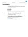
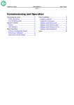
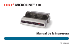
11/07 Rev. 4.03-01
USER MANUAL
AP 3.4
Commissioning and Operation
Connecting the printer ................................... 2
Overview connectors ................................. 2
Connecting the printer ............................... 3
Operator Controls ......................................... 4
Buttons ...................................................... 4
LED indicators ........................................... 5
Basic Operations ........................................... 6
Printing a Configuration Report ................. 6
Performing a Calibration ........................... 7
Performing a Factory Reset ...................... 8
Driver Installation ...........................................9
Selecting a driver .......................................9
Installing the Standard Driver ..................10
Installing the USB Driver ..........................10
Installing the label layout program ...............11
Xbar .........................................................11
NiceLabel .................................................11
2
11/07 Rev. 4.03-01
USER MANUAL
Commissioning and Operation
AP 3.4
Connecting the printer
Overview connectors
F
E
A
B
[1]
C
D
Printer connectors (rear side of the device).
y Centronics connector (parallel port) [1C]
For parallel port connection. Mostly it is connected to the printer port of a PC.
y RS232 connector (serial port) [1D]
For serial port connection. Mostly it is connected to the COM. port of a PC.
y USB-Anschluss [1B]
y AC power socket [1E]
For AC power connection.
3
11/07 Rev. 4.03-01
USER MANUAL
Commissioning and Operation
AP 3.4
Connecting the printer
WARNING!
Printer is driven by mains voltage! Touching of live parts can cause lifethreatening body currents and burns!
« Make sure, that the printer is switched off, before connecting the power cable.
« Only connect the printer to a power socket that provides the correct voltage,
which can be found on the rating plate.
« Only connect the printer to a grounded power socket fitted to authorized
standards.
« When laying the power supply cable, ensure that:
– no one can trip over it.
– no one can step on it.
– the power supply cable can be pulled out of the power outlet, if
necessary.
1. Leave the power switch [1A] at the “O” Position.
2. Connect the power supply plug to the power jack [1E] and the other end of
the cord to your AC outlet [1F].
3. Connect the printer with any standard Centronics cable to the parallel port of
the host computer and to the Centronics connector [1C] of the printer.
¯ Alternatively, you can connect the printer as follows:
– With a serial cable to the RS232C port of your computer.
– With a USB cable to the USB port of your computer.
4
11/07 Rev. 4.03-01
USER MANUAL
Commissioning and Operation
AP 3.4
Operator Controls
Power switch
[2]
Operator controls of the printer.
Buttons
There are three buttons [2], each having two basic functions.
BUTTON Pressed at normal status
Pressed during power-on
FEED
Feed a label.
Perform a self test for configuration report.
PAUSE
Stop the printing process
Resume the printing job after
press it again.
Perform the media calibration.
CANCEL
Interrupt and delete the printing job.
Force the printer to continue
working after an error had
been solved.
Reset the settings at
E2PROM.
[Tab. 1]
Overview buttons.
y FEED Button
The FEED button forces the printer to feed one label when printer is idle (not
printing) or if in PAUSE state.
Holding down the FEED Button then turning on the power switch, the printer
will perform a self test and a configuration report will be printed.
5
11/07 Rev. 4.03-01
USER MANUAL
Commissioning and Operation
AP 3.4
y PAUSE Button
The PAUSE Button stops and restarts the printing process in normal operation. If the PAUSE button is pressed while printing is in progress, the printing
stops once current label is completed. Press this button again to restart the
printing.
Holding down the PAUSE Button then turning on the power switch, the printer
will perform the media sensor calibration.
y CANCEL Button
The CANCEL Button interrupts and deletes the current printing job. If there is
an error indication occurs, pressing this button to cancel the error indication.
Holding down the CANCEL Button then turning on the power switch , the printer will perform a system reset , all the parameters which are stored in
EEPROM will be rest to default value.
LED indicators
There are three LED indicators on the front panel, ”READY”, ”MEDIA” and
”RIBBON”. These indicators display the operation status of the printer.
LED
Meaning
READY
The READY indicator will remain lighted except if any of the following conditions prevail.
- Receiving data from host
- A fault condition
MEDIA
The MEDIA indicator will remain on for the normal operation of
the printer.
- The printer is at PAUSE state
- Blinking – Media run out (READY will be also blinking)
RIBBON ON - under thermal transfer mode with ribbon installed.
OFF - under direct thermal mode. (No ribbon installed)
Set by Windows driver or command.
- Blinking - Ribbon run out (READY will be also blinking)
[Tab. 2]
Overview LED indicators.
6
11/07 Rev. 4.03-01
USER MANUAL
Commissioning and Operation
AP 3.4
Basic Operations
Printing a Configuration Report
1. Turn off the printer. Press and hold the FEED button.
2. Turn on the power.
3. READY indicator blinks, release FEED button.
4. The printer will perform a self test and print out a configuration report [3].
5. READY indicator stops blinking and lights up.
6. The following information will be printed on this report.
¯ After self test the printer will enter character dump mode. For normal operation press the CANCEL button to stop dump mode.
[3]
Configuration report.
7
11/07 Rev. 4.03-01
USER MANUAL
Commissioning and Operation
AP 3.4
Some information in the configuration report are important, please check
them after the self test:
Item
Meaning
Printer programming
language
The printer programming language is listed on the
first line of the report . There are two different languages (PPLA and PPLB), Please check for correct version.
CHECKSUM
The CHECKSUN of the FLASH ROM is listed on
the eighth line, It should be 0000.
Media height:
The height of the media (label paper) is list on the
second line from the end. Please check this value
if the height of the media is less the 2 inches
(50 mm). The listed value should be very close to
the height of the media plus the height of one gap,
otherwise the calibration of media sensor is required.
Label count and length This message shows the number of labels and
length has been printed since it was produced at
factory.
[Tab. 3]
Items on the Configuration Report.
Performing a Calibration
After the media loaded, it is necessary to do the calibration for the label size
detection.
1. Press and hold the PAUSE button. Turn on the power.
2. MEDIA indicators will blink, at this point release Pause button.
The printer will feed the labels for 12 inches.
MEDIA indicators stop blinking and remain illuminated.
During the media calibration, 12 inches of media will be fed out. MEDIA indicators will be blinking for few seconds during calibration is proceeding. Then
turn on printer again after the calibration is completed. Without the proper calibration, the gap detection will not stable especially for the small labels (less
than 2.0 inches in height).
After the calibration, all the related parameters will be stored in the EEPROM
which is located on Main board.
¯ This procedure is very important and must always be carried out after installation and every time the media type is changed. Failure to do so will result in
the gap and label-empty detection being incorrect.
8
11/07 Rev. 4.03-01
USER MANUAL
Commissioning and Operation
AP 3.4
Performing a Factory Reset
If you would like to reset the printer to its factory defaults after certain commands have been sent or settings changed:
1. Turn off the printer.
2. Turn on the power. Press and hold the CANCEL button.
3. Ribbon indicator blinks, release the button.
Ribbon indicator stops blinking and lights up.
The following parameters automatically reset.
– Label parameters
– Heat(Darkness)
– Speed
– Symbol set (language)
– Others for specific interpreter
¯ All settings stored in non-volatile E2PROM cannot be destroyed even by
turning the printer off.
¯ It is necessary to perform label sensitivity calibration after resetting.
¯ The printed label count can not be reset.
9
11/07 Rev. 4.03-01
USER MANUAL
Commissioning and Operation
AP 3.4
Driver Installation
Selecting a driver
Two printer drivers are delivered with the printer, each in different versions
for the following operating systems:
y
y
y
y
y
Windows 95
Windows 98
Windows 2000
Windows NT 4.0
Windows XP
The drivers are referred to in the following as „Standard Driver“ and „USB
Driver“.
USB Driver
Install the USB Driver, if:
– The print jobs are supposed to be sent via USB interface.
– The AP 3.4 is supposed to be operated with the optional keyboard,
independent of a host computer.
Standard Driver
In all cases, which are not mentioned under „USB Driver“, it is recommended
to install the Standard Driver and the layout software „NiceLabel“.
y Installing drivers: See the following paragraphs.
y Installing label layout programs: see section Installing the label layout
program on page 11.
10
11/07 Rev. 4.03-01
USER MANUAL
Commissioning and Operation
AP 3.4
Installing the Standard Driver
Requires the Adobe Reader to be installed on the computer.
Printer Documentation
64-xx / DPM / ALX 92x / TTX 67x / AP 7.t
TDI / Options
Link information to your product
[4]
CD „Printer Documentation“.
1. Insert the CD „Printer Documentation“ [4] (is delivered witih the printer).
The CD starts automatically.
The window „Printer Documentation“ opens.
2. Click „Printer drivers and label software“.
The selection window „NiceLabel SE CD“ opens.
3. Click „Installl“ and then „Printer Drivers“.
The installation wizard welcomes you.
4. Follow the instructions of the installation wizard.
5. If you are requested to select a printer type, note the following:
– Click „AP 3.4 PPLA“ for an AP 3.4 with Datamax interpreter.
– Click „AP 3.4 PPLB“ for an AP 3.4 with Eltron interpreter.
6. Further follow the instructions of the installation wizard.
The driver files are copied to the computer.
7. If you are back to the selection window „NiceLabel SE CD“, click „Back“ and
then „Exit“.
8. Close the Adobe Reader.
Installing the USB Driver
1. Insert the CD „Label Printing Software“ (is delivered with the printer).
2. At the computer, click Start > Settings > Printer and fax devices.
3. Click File > Add printer.
The installation wizard welcomes you.
4. Follow the instructions of the installation wizard.
5. If you are requested to select a printer type, click „Have disk“.
A file selection dialog opens.
6. Select on CD the file „\Utilities\AP34\WINDOWS Driver\ BS\oemprint.inf“,
where OS stands for the Operating system on your computer.
7. Further follow the instructions of the installation wizard.
11
11/07 Rev. 4.03-01
USER MANUAL
Commissioning and Operation
AP 3.4
Installing the label layout program
Xbar
¯ Is required for the standalone operation of the printer with a keyboard (option)
connected.
1. Insert the CD „Printer Documentation“ (is delivered witih the printer).
2. Go to folder „\Utilities\AP34\Xbar Labelprogram“and start the „*.exe“- file
which is stored there.
3. Follow the instructions of the installation wizard.
NiceLabel
1. Insert the CD „Printer Documentation“ (is delivered witih the printer).
The CD starts automatically.
The window „Printer Documentation“ opens.
2. Click „Printer drivers and label software“.
The selection window „NiceLabel SE CD“ opens.
3. Click „Installl“ and then „NiceLabel“.
The installation wizard welcomes you.
4. Follow the instructions of the installation wizard.