1
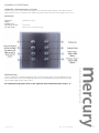
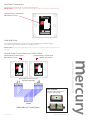
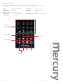
multi-room audio • lighting controls • energy management MRA Multi-room Music Hub Installation and User Manual Revision E • R Hamilton & Co Ltd. 2014 Making sound choices www.hamilton-litestat.com Contents Introduction to your Mercury® Audio System 3 Initial system test set-up 4 Initial system test set-up diagram 5 Safety instructions 6 Audio system connection diagram and technical specification 7 Typical set up of installed system diagram 8 RJ45 connection 9 Control plate options 10 Hub Installation Dimensions and tools 11 Mounting and installing the Mercury hub ® Speaker connection Installation of wall plates 12-13 14 15-18 Wall plate connection via CAT5e cabling 19 IR remote control 20 Mercury Touch Screen User Guide 21 - 24 Dock Assistant Set-up 25 - 26 Remote App Accessing your Spotify Account to stream Audio to any zone. 26 28 - 29 30 Disclaimer and warranty 32 multi-room audio and lighting controls External devices and DAB radio (for MRAD option only) ® Issue Date: May 2014 1 - MRA - User Manual REV_D E&OE 2 Introduction Thank you for purchasing the Mercury® Audio System. The multi-room audio system provides the versatility of controlling music played in different areas of a property; from the living areas to the bathroom, and even the garden! Installing these systems facilitates a new level of luxury for the property owner, affording the flexibility of selecting which sounds they want to listen to, where and when. Listen to your music from any room in your home, any time! • Listen to four individual sources simultaneously. • Create the perfect mood by playing your favourite playlist throughout the entire house for your whole family to enjoy. Classical in the lounge, blues in the kitchen, and rap in the kids room - all at the same time. • Control your music via your iPhone, iPod or iPad, a wall mounted controller or remote control from multiple sources, including your MP3 player. • The Hamilton multi-room music systems make it easy to listen to your entire music collection from anywhere in your home. • Control your Skybox, using the IR remote via the wall plate. In the box • Mercury MRA4 Audio System hub. • Power supply lead. • Yellow CAT5 cable (for initial system testing of Control Plates). • RCA to 3.5mm Jack audio cable. • Wall mounting template. • Mercury IR remote control (batteries included). • 1x wall mounting kit including 3x M8 40mm dome head screws and 3x brown rawl plugs. If any of the items above were not in the master pack when originally opened, please call Hamilton Litestat on 01747 860088 and ask for technical support or email [email protected]. multi-room audio and lighting controls Thank you again for purchasing your Mercury® Audio System. ® Issue Date: May 2014 1 - MRA - User Manual REV_D E&OE 3 Initial system test set-up using Mercury® control plates See diagram on page 5 • Connect the supplied CAT5 cable to the audio system through control plate 1 port. Then connect the CAT5 cable to the wall plate. • Set the dip switch on the back of the plate to zone 1. • Connect 1 speaker into the zone 1 speaker outputs. • Connect the supplied 3.5mm jack to RCA cable to audio source 4 and connect any portable audio source (mp3 player or smart phone are ideal). • Connect power supply lead to audio system. • Turn the system on at the main switch by the power lead terminal. • Using the connected control plate press ‘source 4’ • You should now hear the music from your connected device being played though the speaker. Trouble shooting If you don’t hear the connected audio source: • Ensure the volume is tuned up on the control plate • Ensure the volume is tuned up on the Source device • Check ALL connections. Ensure the source device is connected to ‘Source 4’ and ‘Source 4’ is selected on your control plate. This initial set up is a simple, quick, and reliable way to set up your Mercury Multi-Room Audio System. It is also a good way of testing any connection or multiple accessories for larger installations. The system is designed to be adaptable and can be expanded once a basic installation is up and running. multi-room audio and lighting controls ® Issue Date: June 2014 i - MRA - User Manual REV_E E&OE 4 multi-room audio and lighting controls ® Issue Date: May 2014 1 - MRA - User Manual REV_D E&OE 5 Safety Instructions WARNING: LIVE MAINS IS EXPOSED WHEN THE COVER IS REMOVED DANGER Isolate mains before removing cover Danger 240 Volts For the continuous safe operation of this product, the following must be complied with AT ALL TIMES. Read Instructions – all operating and safety instructions should be read before the system is operated – instructions should be retained for future reference. 2. Care should be taken to prevent the chance of ingression of dust, liquids or other foreign bodies spilling/falling into the equipment. The equipment should not be exposed to any dripping or splashing - no objects filled with liquid should be placed on the unit. 3. This equipment must be installed by a competent person. 4. This equipment must be earthed at all times. 5. The mains power feed may come from either an earthed domestic or a switched fused spur (both) must be protected by an earthed fused link rated at max 3A in accordance with BS1362 and installed by a qualified electrician. 6. This equipment must be protected from damp and humid environments and is only suitable for interior installation. 7. The equipment should be mounted on a suitable wall or within a cabinet with adequate ventilation away from any heat source. To prevent injury this apparatus must be securely attached to the wall in accordance with the installation instructions. 8. For any installation queries please see the Hamilton Litestat website or contact Hamilton’s technical support. 9. No user servicable components within the unit. a rnig: When making off RJ45 connections it is imperative that the termination is correctly wired to T-568A wiring standards (see page 9). Incorrect wiring can result in irreversible damage to the controller and MRA4 hub. This will invalidate the product warranty. W multi-room audio and lighting controls 1. For future reference please write your Mercury® serial number below, the number can be found inside the Mercury® casing. Serial Number: ® Issue Date: May 2014 1 - MRA - User Manual REV_D E&OE 6 ® 1 - MRA - User Manual REV_D E&OE IEC Socket Inlet Speaker Level Outputs Zone 1-4 RS232 Connection IP Network Port Mercury® iDock Data Port Mercury iDock Audio Port Control Panel Port 1-4 Line Out 2. 3. 4. 5. 6. 7. 8. 9. 12. RCA Stereo Audio Input Source 1-4 11. IR Emitter output source 1-4 10. DAB Aerial Mains Power Switch 1. 2 1 3 9 4 5 6 Input: Mains Frequency: Rated Current: Max Output Power per Channel: Number of zones: No. of line levels audio inputs: No. of demote dock module inputs: Remote control interface: Number of IR out: 7 20W 8� 4 4 1 IP and RS232 4 240V~ 50/60Hz 3 Amp 10 TECHNICAL INFORMATION multi-room audio and lighting controls Issue Date: May 2014 7 8 11 Pre-amplifier Unit Source Input: Stereo Phono Pair: Input Impedance: Dimensions: Weight: 12 1-4 x4 10K � 450 x 205 x 69 mm 5.3kg *Router not available from Hamilton Litestat • Wireless App control (ethernet connection to router*) • Play any source in any zone • Four audio sources (line inputs) • 20+20 Watts per channel (left and right speaker) • Control four zones (rooms) ® 2 4 Left Left Control all sources in all zones/rooms via the Mercury App 4 3 1 3 2 Zone/Room 3 Right 1 Left 4 3 2 4 Zone/Room 1 1 3 2 Right 1 Left Zone/Room 4 Right Zone/Room 2 Right Wireless connection TO App via home router Home Hub Router* www.hamilton-litestat.com mra4 ® 1 - MRA - User Manual REV_D E&OE multi-room audio and lighting controls Issue Date: May 2014 Four zone set up with Bluetooth and audio bridge connected plus App control via router MRA4 4 Zones/Rooms of Music Typical set-up of installed system multi-room audio 8 Stream music FROM your device via Bluetooth connectivity Audio Bridge Bluetooth Hamilton Shielded CO AX Cable must be used Source 3 Source 2 Source 1 4 Line Level Audio Inputs Important Notice RJ45 CONNECTION When making CAT5e / RJ45 connections, it is imperative that the termination is correctly wired to T-568A wiring standards (below). Incorrect wiring can result in irreversible damage to the controller and MRA hub, this will invalidate the warranty. CAT5e cables are assembled according to the T568A standard. The T568A standard requires the cable end to terminate the internal coloured wires in the order below, as viewed from the top down: green-white, green, orange-white, blue, blue-white, orange, brown-white, brown. A CAT5e tester must be used to test connections prior to connecting the system. Note: Maximum cable run length from MRA4 hub to controller = 100m multi-room audio and lighting controls ® Issue Date: May 2014 1 - MRA - User Manual REV_D E&OE 9 Control Options WALL MOUNTED PLATE Mechanical Button MERCURY® IR REMOTE Glass Capacitive Touch MERCURY iOS Touch Screen App Available from the AppStore IR Remote Control MERCURY APP IR PASS-THROUGH The MRA4 hub has an internal IR pass-through that is compatible with the Sky satellite TV box, allowing you to use your Sky remote to control the Sky box via the Hamilton wall mounted plate. multi-room audio and lighting controls The Hamilton Mercury ® App is available for download on iTunes / AppStore, for information or how to set up Please see page 26. ® Issue Date: June 2014 i - MRA - User Manual REV_E E&OE 10 Hub Installation DIMENSIONS All dimensions are shown in millimetres (mm). Dimensions: Weight: 450 x 205 x 69 mm 5.3kg multi-room audio and lighting controls TOOLS To install your system you will need: • • • 6mm masonry drill bit and drill Large Phillips head screw driver Small flat head screw driver ® Issue Date: June 2014 i - MRA - User Manual REV_E E&OE 11 Mounting and Installing the Mercury® Hub The System is designed to hang vertically and is supplied with a fixing kit and template showing the required position for the screws. (124mm apart and 54mm below where the top of the system will sit.) 1) Using the fixing kit provided and installation template mark the 3 required screw holes positions ensuring the system is square. Leave a gap of at least 30mm at the top and enough room around the system for adequate ventilation. 2. Drill the 3 holes with 6mm masonry drill bit. 4. Screw top 2x M8 40mm dome head screws supplied in fixing kit into raw plugs with Philips screwdriver leaving between 5mm and no more than 10mm of the screw protruding the wall surface as not to damage internal components. multi-room audio and lighting controls 3. Insert 6mm brown raw plugs. 5. Remove system from box and packaging ® Issue Date: June 2014 i - MRA - User Manual REV_E E&OE 12 6. Align keyhole slots on the reverse of system with fixing screws. 8. Lower system onto screws until it slots into position. Ensure the system is firmly in place. 10. Insert final screw in position 3 through the extrusion to hold the bottom of system tight to the wall. multi-room audio and lighting controls ® Issue Date: May 2014 1 - MRA - User Manual REV_D E&OE 13 Speaker Connection The maximum cable run is 33m from hub to speaker. The reccomended speaker cable (minimum) 2 x 0.75mm (21 AWG) twin axial. SPEAKER OPTIONS Single 6½” white stereo ceiling speaker Pair of 5¼” white ceiling speakers Pair of 4” white speakers Please refer to the individual speaker manual for installation. Multiple Speaker Connection Using 8OHM speaker (must be wired paralell) R L - - - + + + - - - + + + 2 speakers per channel maximum Right Channel + Left Channel + + + Speaker Output Speaker Output Speaker Connection Single Stereo Speaker Connection Right Channel + Left Channel + multi-room audio and lighting controls 2 speakers per channel maximum IMPORTANT Speaker must be polarised (i.e. + to + - to -) if speakers are wired out of phase it will impair the sound quality. ® Issue Date: June 2014 i - MRA - User Manual REV_E E&OE 14 Installation of Wall Plates OVERVIEW - Capacitive Touch Controller The Mercury® CPT4+4 is a wall mounted control plate used to control the audio function in a room that is fed from a MRA4 audio hub. The CPT4+4 provides source selection and volume control with backlit capacitance sensing buttons and an IR to receive remote control signals for room and remote source control. SPECIFICATION Dimensions: Weight: Network ports: Network Termination: Max cable length: Source selection buttons 1-4 90x89x32 (HxWxD) 340g 1 CAT5e RJ45 MRA4 Hub to control panel 70M Volume and control buttons 5-8 Volume Up Press once to select desired source. LED will light to show current source. Volume Down Next Track/Song/ DAB Station Previous Track/ Song/DAB Station multi-room audio and lighting controls ® Issue Date: June 2014 i - MRA - User Manual REV_E E&OE 15 INSTALLATION The CPT4+4 installs into a standard UK single gang 35mm metal or dry lining wall box. For best installation have the CAT5e cable enter from above the back box. Terminate the CAT5e cable with the appropriate RJ45 for the cable type to T568A straight through wiring standard. 1. Pull CAT5e cable through plastic wall mount. 2. Using supplied 35mm screws. Fix in wall mount to back box. Do not over tighten and ensure moulding is level. 4. Pull CAT5e cable through Linea frame. Push on Linea frame around plastic mounting bracket ensuring cut out is at the bottom. Ensure notch is at the bottom of frame. This is used when removing the control plate multi-room audio and lighting controls 3. Remove Linea frame from packaging. 7. Remove Control Front Plate from packaging ® Issue Date: May 2014 1 - MRA - User Manual REV_D E&OE 16 8. Insert CAT5e cable until it clicks. (Refer to page 19 for zone setting). 9. Carefully push control plate into frame and mounting bracket for a firm fit. REMOVAL OF GLASS PLATE Should it be neccssary that you need to remove the glass cover plate, you will note a small cut away at the bottom of the chrome frame gently slide a small plastic tipped screwdriver under the glass and ease the glass off the frame. If using a metal screwdriver to do this be careful not to scratch the underside of the glass. multi-room audio and lighting controls ® Issue Date: May 2014 1 - MRA - User Manual REV_D E&OE 17 Installation of Wall Plates OVERVIEW - Mechanical Button Controller The Mercury® A4+4 is a wall mounted control plate used to control the audio function in a room that is fed from a MRA4 audio hub. The A4+4 provides source selection and volume control with white LED back light and IR receiver. Specification Dimensions: Weight: Network ports: Network Termination: Max cable length: 86x86x32 (HxWxD) 1 CAT5e RJ45 MRA4 Hub to control panel 100M Source selection buttons 1-4 Press once to select desired source. LED will light to show current source. The A4+4 installs into a standard UK single gang 35mm metal or dry lining wall box. For best installation have the CAT5e cable enter from above the back box. Terminate the CAT5e cable with the appropriate RJ45 for the cable type to T568A straight through wiring standard. For installation steps please refer to the capacitive touch installation minus steps 4 - 6. multi-room audio and lighting controls INSTALLATION ® Issue Date: June 2014 i - MRA - User Manual REV_E E&OE 18 Wall Plate Connection Wall plate DIP switch MUST be set to the corresponding zone. Please note: If the RJ45 plug is wired incorrectly to CAT5e cable it could cause irreversible damage. Hamilton Mercury® control panel 1 DIP switch set to zone 1 Add Wall Plate One additional wall plate may be added in each zone by duplicating the wall plate settings, as shown in the diagram below. Maximum two controller per zone. Please note: If a incorrectly wired cable is used i.e. cross over connector, it could irreversibly damage the system. 2x Wall Plate Connections via CAT5e Cable Hamilton Mercury® control panel 1 DIP switch set to zone 1 Hamilton Mercury® control panel 2 DIP switch set to zone 1 Also Available: Hamilton CAT5e Punch Down Coupler - Part No. TBC multi-room audio and lighting controls RJ45 coupler must be wired to the schematic shown below MRA4 Mercury® Audio System ® Issue Date: June 2014 i - MRA - User Manual REV_E E&OE 19 IR Remote Control Credit card sized convenient IR remote control. For use with both audio and lighting systems giving individual channel lighting control and scene recall options, volume raise and lower, skip and repeat. Range: Case Material: Keypad Material: Infrared Frequency: Humidity Range: Operating Temp.: 20-30ft (6-9m) Standard ABS Plastic Membrane 38KHz others available 10% to 90% non-condensing +5°C to +40°C Storage Temp.: Dimensions: Power Supply: Power Consumption: -40°C to +70°C 94 x 60 x 8 mm 1xCR2025 Lithium Coin Battery Approx. 50mA at IR transmit Controls for Mercury® lighting control system Source Selection Stop and Play Skip and Repeat multi-room audio and lighting controls Mute Power Off Volume Raise and Lower ® Issue Date: June 2014 i - MRA - User Manual REV_E E&OE 20 Mercury Touch Screen Instructions to set-up and control you Mercury Audio System Screen 1 Home Screen Touch Screen sold separately Using the touch screen you can choose to control your Mercury Audio System and Mercury Lighting System controls. Please select the Audio section to follow these instructions. If you have previously been using the Mercury App the Touch Screen will show you previous setting including Zone names, your chosen Source names, and your pre-set favourite DAB radio stations. The 3 buttons on the bottom of the screen are shown on all screens and allow you to: Turn off your audio system Go to the Home screen Turn on/off your connected lighting and audio systems. Screen 2 Select Zone Once you have selected the Audio section the following screen will appear . The Zone can be re- named to personallise your system and make it easier to use. See Screen 10 Screen 3 Select Audio Source Select DAB Radio to follow this demonstration. See screen 4 for DAB Radio See screen 5 for USB Dock See Screen 7 for CD See Screen 11 for AUX Issued Date: June 2014 i - MRA - User M anual Rev_E E&OE 21 Screen 4 DAB Radio Screen From the DAB Screen you can TUNE in the radio by pressing the + & - buttons to browse for your favourite radio stations. The Name of the station will appear automatically. To set the 3 PRE-SET stations, find and select the station you which to pre-set, then Press and hold button until it turns RED. The name of the station name and RDS. Information will appear on screen. Screen 5 USB Dock Screen By selecting the ‘USB Dock’ the screen will display this interface allowing you to Play, Pause and Skip through tracks from your connected iPhone, iPad or iPod device The track details will appear in the info window. To go BACK to the Source menu (Screen 3) press the top left arrow . Screen 6 CD Screen By selecting ‘CD’ source from screen 3. The Mercury Audio will link to your connected CD Player. The Touch screen enables you to turn the volume up / down & mute. The Touch Screen plate includes an infra-red receiver and it can be setup to allow your existing CD Player remote to work from a room in the house by aiming the remote at the touch screen. Issued Date - June 2014 i-MRA - User Manual Rev_E E&OE Press the EQ button to access the EQ Screen (Screen 8) 22 Screen 7 AUX Screen This screen is identical to screen 6 (CD Player). The Touch screen enables you to turn the volume up / down & mute. Press the EQ button to access the EQ Screen (Screen 8) Screen 8 EQ Screen By selecting the EQ button shown on any Source screen you will be able to adjust the Treble, Base, and Balance to fine tune your audio system. Use the arrow buttons to adjust. This controls all 4 Zones at the same time. Issued Date: June 2014 i-MRA - User Manual Rev E 23 Screen 9 Audio Settings Prese the Hamilton Logo from any screne to enter the Settings for both Audio and Lighting controlls. The Audio Settings will appear first. This alows you to fine tune your system: Redefine Zones Reduce the maximum volume Set sourse type Rename sourses Rename zone areas Editing any of these setting will prompt the keyboard to appear. Turn Party Mode on/off Party Mode allows you play the same music across all the whole system and by selecting additional zones without having to turn to each control plate in each zone individually. Screen 10 Keyboard Screen The keyboard screen will apear for you to type in Source and Zone names to help personallise your system and make it easier to use. Press the arrow to go back or entre text and press the tick box to confirm the change. Screen 11 Keypad Screen If you press on the icon the Keypad screen will appear to prompt you to input a number between 1 and 4. This will allow you to turn on individual zones from the touch screen. Issued Date: June 2014 i - MRA - User Manual Rev E 24 ® Customer Service Dept Tel 01747 860088 www.hamilton-litestat.com MERCURY DOCK www.hamilton-litestat.com POWER I ZONE2 R L + - + - R L + - + TX-GND-RX RS232 ck Do A 2.1 2 IP Mercury Dock Module front view connected to a iPhone / iPod touch using a USB lead. to connect your iTunes library to all audio zones. This device will act as a Media Player for your Mercury system With the Mercury Dock Assistant App installed 2 3 I R OUT ONLY 4 1 R L 2 R L 3 R L AUDIO SOURCE 4 R L Once setup you can used the Mercury Touch Screen or another iOS device to brows and play your iTunes library or your Spotify Account content wirelessly from you iPad, iPhone or iPod touch. Control the connected iOS docked device from the touch screen. CONNECT MERCURY TOUCH SCREEN USING CAT5e CABLE CONTROL PLATES 1 See and control your iTunes or any web based audio streaming player directly from the Touch screen and listen in any zone. 1 2 DATA AUDIO DAB AERIAL REMOTE DOCK Download the Mercury App and the Dock Assistant App using the App Store CONNECT MERCURY DOCK AUDIO USING CAT5e CABLE Mercury Dock Module back view showing data & audio connections 5V R L + - + - ZONE 4 LINE OUT CONNECT MERCURY DOCK DATA USING CAT5e CABLE R L + - + - ZONE 3 SPEAKER OUTPUTS ZONE 1 CONNECT IP PORT TO ROUTER USING CAT5e CABLE INPUT: 240V~ MAINS FREQUENCY: 50/60Hz RATED CURRENT: 3A O Setting up your Mercury Dock to connect an iOS iPhone - iPod Touch Or iPad to act as a media hub to access your iTunes Library and Spotify account from the Touch Screen or iOS App. mercury 25 Setting up the Dock Assistant App and the Mercury App to stream audio from Spotify through the Mercury Dock The Mercury Audio System is designed to be as adaptable as possible, providing multiple ways to connect to your favourite music throughout your home. Using the Dock Assistant, you can access web services such as Spotify through the Mercury App on any Apple iOS device. This enables the Mercury Audio System to stream audio from your Spotify account around your home. Setting up the Dock using the Dock Assistant app Set up your Mercury MRA4 audio system with at least 1 audio source, a control plate and speakers connected to zone 1. –See the initial setup for the simplest installation on page 5. The system can be installed in stages. Setting up this dock assistant App will likely be the final part of your installation. Connect your Mercury MRA4 IP port to your router from the built in IP port using CAT5 cable. Connect your Mercury Dock using the Audio and Data sockets. Please follow the installation instructions included with the Dock. It is recommended that you try to play a track from the docked device, before setting up the Dock Assistant App. Download the Mercury Control App and Mercury Doc Assistant App onto the device you wish to dock from the App Store. Mercury Control App Dock Assistant App Connect an Apple iPod Touch, iPhone or iPad to the Dock using a USB lead. Ensure this device has the lasted Mercury Dock assistant App is loaded. The Mercury Dock App is available as a free download available from the App Store for all iOS devices. Leave the device connected to the dock. The dock will charge the device while it is connected. This will act as a music library and internet player, connecting you with your music from any zone or multiple zones in your home. All controlled wirelessly via the Mercury App on another iPhone or iPad or the Mercury Touch Screen. Connect another Apple iOS (iPad/iPhone) device to the same Wi-Fi network that you connected the MRA4’s IP port and ensure the Mercury Dock App Assistant is loaded. Follow the Mercury Dock Assistant Set-up page 25 in this Audio Manual. Now the MRA4 is connected it can receive audio from web based streaming services such as Spotify and browse your own iTunes Library through the Mercury App of the device connected to the mercury dock. All web based content and your iTunes library can now be access heard and controlled from any or multiple zone. All your control plates will allow you to change the track being played and control the rest of system normally. Issued Date: June 2014 i – MRA – User Manual REV_E E&OE 26 Mercury Audio - Dock Assistant Set-up The Mercury Dock Assistant App allows you to link an Apple iOS device to the system, to access your iTunes library and Spotify account to listen to your music throughout your home. This setup shows you how to link an iPhone / iPod Touch to be used as a media interface. This additional set up should be done once your system is installed. Before you start: 1. Connect the Mercury Audio System to your router through its IP port using CAT5 cable. 2. Connect the Dock’s Audio and Data ports to the Mercury Audio System using CAT5 cable. 3. Download the Dock Assistant App from the App Store onto the Apple iOS device you wish to act as your media interface. Step 1 Launch the Dock Assistant App on your phone, or the device you wish to dock. Select the Mercury Dock Assistant App icon shown in the diagram on the right. Once loaded, the App will display ‘Not Docked’. Step 2 Connect the iOS device to the Dock using a USB lead. The App will display a screen similar to the one on the right. This screen will show your Spotify status and if you are logged in to Spotify The Dock Assistant is now set-up and ready to use! Issued Date: June 2014 i – MRA – User Manual REV_E E&OE 27 Mercury Remote App Home Screen Mercury The App allows you to control your Audio, Lighting & Blind Systems its controls using intuitive interface. Audio Screen After selecting ‘Audio’ the second screen will appear allowing you to connect to your system. Room Selection Select A Source This screen shows you which sources are playing in each zone. Use the slide controls to adjust the volume in each zone. To change the Source being played select edit from the previous screen. Then the ‘Select a Source ’ screen will appear. Pressing the edit button will allow you to rename each zone. Playing your music from your iTunes on a remote device, connected to your Mercury Dock. Browse your iTunes Library Access iTunes playlists or browse music by Artist or Album title. Issued Date: June 2014 Search your iTunes Library of docked device directly from the Mercury App Select a track to Play View track selected artists. from Play track to view album cover. The track will play and the Mercury App and Mercury Touch Screen will show what is being played and will even show the album art work. i – MRA – User Manual REV_E E&OE 28 Accessing Your Spotify account to enable you to Stream Audio to any Mercury Audio Zone Stream Music from your Spotify account to all zones across your home. Once set up you can control your Spotify playlists from the Touch screen or Mercury App. Spotifi Login Screen Spotifi Login Screen Connect and Log-in to your Spotify Account using the Spotify App to stream music through your Mercury audio system. Once logged in, use the Spotify App to control the track you are listening to through you Mercury Audio System. Playlist Screens Select a play list to listen to. This will be streamed single or multiple audio zones using the Party Mode from the Mercury App. Once selected the Playlist will stream the audio from Spotify to your Mercury Audio System. Now Playing Now Playing screen through Spotify. when playing music The track information and artwork will also be displayed on a connected Mercury Touch Screen Issued Date: June 2014 i – MRA – User Manual REV_E E&OE 29 Connection of External Devices The system has four line level audio inputs for connecting peripheral audio devices. Note: For MRA4D Model, with internal DAB radio the system line level audio output will be occupied by the DAB source. Other Devices iPhone App This Hamilton Mercury® multi room music hub can be controlled remotely using the Mercury® App on devices including Apple’s iPhone, iPod and iPad. This App is available as a free download from the Apple App Store. Wireless Bluetooth® Reciever For added flexibility your Mercury® multi-room music hub can be connected from a peripheral audio wireless adapter or Bluetooth® audio adapter directly into one of the four source inputs on your MR4A system. A wireless router or Apple Airport Express will enable you to stream music from a WIFI enabled wireless devices. If using Apple Airport Express, the device will need to be connected to your router to secure an internet connection. Bluetooth Setup Instruction Plug in the Mercury Bluetooth Receiver with the included DC 5v power adapter. Connect the Bluetooth Receiver to the MR4A Multi-room Music Hub using either a 3.5mm Jack to RCA cable as shown in photo 1, or a RCA to RCA cable as shown on photo2. Photo 2 At the point of power up the Bluetooth receiver will enter discovery mode, this means the Bluetooth receiver will be available for pairing for 5 minutes. During this time, up to 8 different pairings can be made using compatible Bluetooth devices. After 5 minutes the Bluetooth receiver will enter sleep mode, this means the Bluetooth receiver will not be available to make any new pairings. During sleep mode it is possible for all paired devices to connect to the Bluetooth receiver as long as the receiver is in range and no other device is connected. If you want to create a new pairing and the Bluetooth receiver has already entered sleep mode you will need to reset the power on the Bluetooth receiver. The Bluetooth receiver will now be in discovery mode for the next 5 minutes. Up to 8 pairings can now be made including all existing pairings before the power was reset. After 5 minutes the Bluetooth receiver will enter sleep mode and no new pairings can be made. multi-room audio and lighting controls Photo 1 DAB Radio (for MRA4D option only) If you have purchased an MRA4D with an internal DAB radio, when connected to a DAB aerial this will allow you to enjoy digital quality radio throughout your property. When used in conjuction with the itunes app you can store your favourite DAB stations and view the chosen station on your connected Apple device, wirelessly through your home. The user can also select the available DAB channels by selecting the next/previous buttons on the control wall plate which will scroll through the available channels in alphabetical order. ® Issue Date: June 2014 i - MRA - User Manual REV_E E&OE 30 Notes . . . . . . . . . . . . . . . . . . . . . . . . . . . . . . . . . . . . . . . . . . . . . . . . . . . . . . . . . . . . . . . . . . . . . . . . . . . . . . . . . . . . . . . . . . . .................................................................................................... .................................................................................................... .................................................................................................... .................................................................................................... .................................................................................................... .................................................................................................... .................................................................................................... .................................................................................................... .................................................................................................... .................................................................................................... .................................................................................................... .................................................................................................... .................................................................................................... .................................................................................................... .................................................................................................... .................................................................................................... .................................................................................................... .................................................................................................... .................................................................................................... .................................................................................................... .................................................................................................... .................................................................................................... .................................................................................................... .................................................................................................... .................................................................................................... multi-room audio and lighting controls .................................................................................................... .................................................................................................... .................................................................................................... .................................................................................................... .................................................................................................... .................................................................................................... ® Issue Date: June 2014 1 - MRA - User Manual REV_E E&OE 31 Disclaimer 1. This equipment is intended for domestic and commercial use including hotels and retail shops. 2. No decorative, abrasive or domestic cleaning products should come into contact with the equipment (further information is available on request). 3. It should not be used in areas of high humidity (bathrooms etc.) nor within reach of a water source. 4. This equipment should be connected to a mains supply of the appropriate voltage (indicated on the product). 5. Care should be taken not to overload the equipment maximum amperage is indicated on the product. 6. No liability can be accepted if the product is installed or used in any other way than for which it was designed. Limited Warranty 7. The equipment is guaranteed against faulty workmanship or materials for a period of twelve months and will be repaired or replaced free of charge on condition that it is returned to the Customer Services Department and that: (i) (ii) (iii) (iv) (v) The equipment has not been overloaded or connected to a supply other than 230/240 volts 50Hz. The installation procedure has been carried out correctly. The equipment has not been taken apart or repaired by any un-authorised person. The Bill of Sale (dated) accompanies the equipment for repair or replacement. The product has not been exposed to decorative or cleaning materials or been stored or installed in area’s of high humidity. This guarantee does not affect the statutory rights of the consumer. In no circumstances can the Company accept responsibility for any loss or damage said to arise from the use of this product. The equipment is manufactured in accordance with the relevant British and European Standards where applicable. Tel: 01747 860088 Email: [email protected] All equipment is manufactured under an accredited BS EN ISO 9001:2008 - Quality Management System. All products listed conform to current British or European standards and the product information is correct at the time of going to press. It is the policy of the company to continually improve products as part of our development programme. Therefore, we reserve the right to alter designs and dimensions without prior notice. multi-room audio • lighting controls • energy management CUSTOMER SERVICES DEPT. Quarry Industrial Estate, Mere, Wiltshire BA12 6LA All accessories are manufactured under an accredited BS EN ISO 9001: 2008 Quality Management System. Illustrations and diagrams are reproduced within the limitations of reproductions and printing processes, and are not binding. Due to manufacturing processes we cannot guarantee an exact colour match and shadings of certain plate and product finishes. Correct as at June 2014 • File Reference: i - MRA - User Guide Rev_E E&OE Issued Date: June 2014 ® Mercury® is a trademark or registered trademark of Hamilton Litestat iPhone, iPod, iPod classic, iPod nano, iPod shuffle, and iPod touch are trademarks of Apple Inc., registered in the U.S. and other countries. The Bluetooth® word mark and logos are registered trademarks owned by Bluetooth® SIG, Inc. 32