1
MRA4
HighPROTEC
Feeder Protection
Device Manual
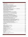
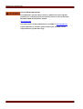
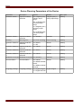
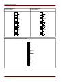
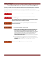
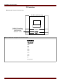
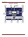
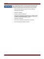
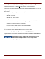
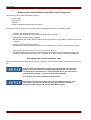
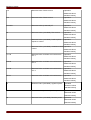
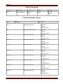
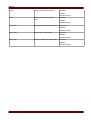
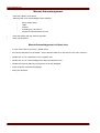
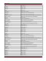
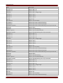
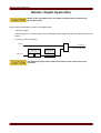
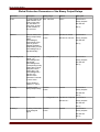
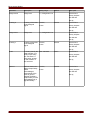
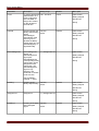
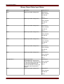
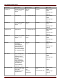
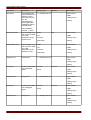
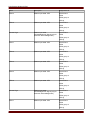
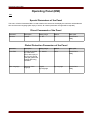
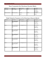
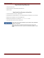
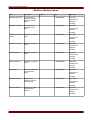
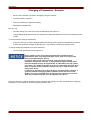
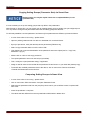
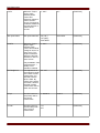
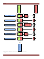
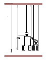
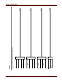
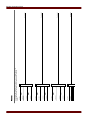
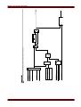
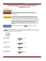
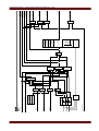
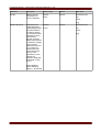
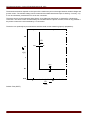
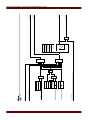
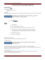
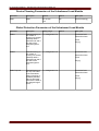
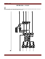
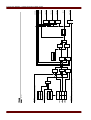
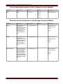
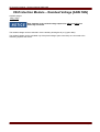
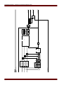
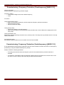
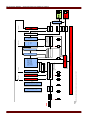
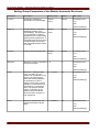
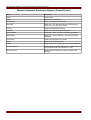
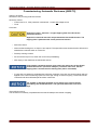
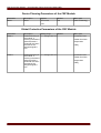
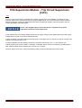
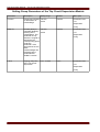
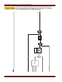
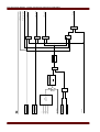
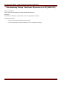
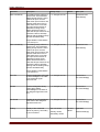
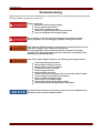
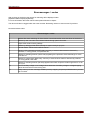
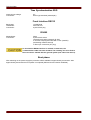
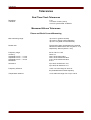
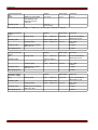
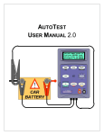
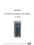
MRA4 Functional Overview
MRA4
79
74
TC
46
49
Inrush
50
BF
50P
51P
67P
67N
Measured and
calculated values
V, VE, I, IE, f,
ϑ , IH2, I2>
3
1
Fault recorder
4
Event recorder
27
59
59N
60
FL
81
U/O
50N
Disturbance
recorder
51N
option
Page 2
standard
MRA4 02.08 UK
COMMENTS ON THE MANUAL.....................................................................................................................9
Information Concerning Liability and Warranty ................................................................................................9
IMPORTANT DEFINITIONS............................................................................................................10
Scope of Delivery ..........................................................................................................................................14
Storage..........................................................................................................................................................14
Important Information ....................................................................................................................................14
Symbols.........................................................................................................................................................15
DEVICE...............................................................................................................................................17
Device Planning.............................................................................................................................................17
Device Planning Parameters of the Device....................................................................................................18
INSTALLATION AND CONNECTION ...............................................................................................................19
Three-Side-View............................................................................................................................................19
Installation Diagram.......................................................................................................................................20
Assembly Groups...........................................................................................................................................21
Grounding .....................................................................................................................................22
Power Supply and Digital Inputs.....................................................................................................................23
Binary Output Relays ....................................................................................................................................25
Digital Inputs..................................................................................................................................................27
Voltage Measuring Inputs ..............................................................................................................................29
Current Measuring Inputs and Ground Current Measuring Input...................................................................31
Supervision Contact (SC)...............................................................................................................................33
Communication Interfaces ............................................................................................................................34
Modbus® RTU via Terminals..............................................................................................................34
Modbus® RTU via D-SUB-plug............................................................................................................35
PC Interface...................................................................................................................................................36
Assignment of the Zero Modem Cable.................................................................................................37
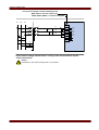
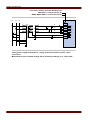
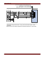
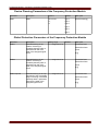
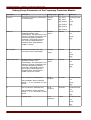
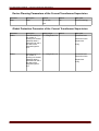
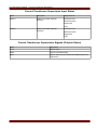
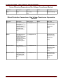
CURRENT TRANSFORMERS (CT)...............................................................................................................38
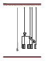
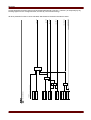
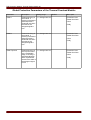
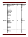
Current Transformer Connection Examples...................................................................................................38
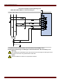
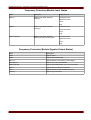
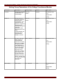
VOLTAGE TRANSFORMERS.......................................................................................................................44
Check of the Voltage Measuring Values.........................................................................................................44
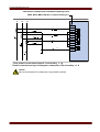
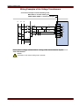
Wiring Examples of the Voltage Transformers...............................................................................................45
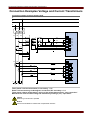
CONNECTION EXAMPLES VOLTAGE AND CURRENT TRANSFORMERS....................................................................51
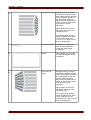
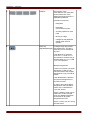
NAVIGATION - OPERATION ......................................................................................................................54
Basic Menu Control .......................................................................................................................................58
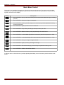
Smart view Keyboard Commands..................................................................................................................59
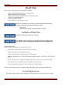
SMART VIEW.......................................................................................................................................60
Installation of Smart View...............................................................................................................................60
Uninstalling Smart view..................................................................................................................................60
Switching the Language of the Graphical User Interface...............................................................................61
Setting up the Connection PC - Device..........................................................................................................62
Set-up a Connection via Serial Interface under Windows 2000................................................................62
Set up a Connection via Serial Interface under Windows XP....................................................................64
Set up a Connection via Serial Interface under Windows Vista.................................................................65
Connected to the Device and Calling up Websites at the same Time.........................................................67
Establishing the Connection via a USB-/RS232-Adapter..........................................................................67
Smart view Troubleshooting................................................................................................................68
Smart view persistent connecton problems.............................................................................................70
Loading of Device Data when using Smart view ...........................................................................................71
Restoring of Device Data when using Smart view..........................................................................................72
Backup and Documentation when using Smart view.....................................................................................73
Printing of Device Data When using Smart view (Setting List).....................................................................74
Saving Data as a txt-file via Smart view................................................................................................74
Offline Device Planning via Smart view..........................................................................................................75
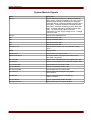
MEASURING VALUES..............................................................................................................................76
Read out Measured Values............................................................................................................................76
Read out of Measured Values via Smart view .......................................................................................76
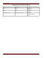
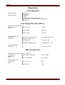
Standard Measured Values............................................................................................................................77
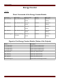
ENERGY COUNTER................................................................................................................................80
Direct Commands of the Energy Counter Module .........................................................................................80
MRA4 02.08 UK
Page 3
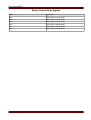
Signals of the Energy Counter Module (States of the Outputs)......................................................................80
STATISTICS..........................................................................................................................................81
Read out Statistics.........................................................................................................................................81
Statistics to be Read-Out via Smart view...............................................................................................81
Statistics (Configuration)................................................................................................................................82
Statistics (Configuration) via Smart view................................................................................................82
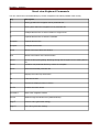
Direct Commands..........................................................................................................................................83
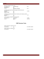
Standard Statistic Values...............................................................................................................................83
Global Protection Parameters of the Statistics Module..................................................................................88
States of the Inputs of the Statistics Module..................................................................................................89
Signals of the Statistics Module.....................................................................................................................89
Counters of the Module Statistics..................................................................................................................89
ACKNOWLEDGEMENTS............................................................................................................................90
Manual Acknowledgement.............................................................................................................................92
Manual Acknowledgement via Smart view............................................................................................92
External Acknowledgements..........................................................................................................................93
External Acknowledge via Smart view..................................................................................................93
MANUAL RESETS .................................................................................................................................94
Manual Resets via Smart view.......................................................................................................................94
ASSIGNMENT LIST ................................................................................................................................95
STATUS DISPLAY ................................................................................................................................110
Status Display via Smart View......................................................................................................................110
MODULE: DIGITAL INPUTS (DIS).............................................................................................................111
Digital Inputs (Standard)...............................................................................................................................112
Global Protection Parameters of the Digital Inputs (Standards)...................................................................112
Digital Inputs Signals (Outputs States).........................................................................................................115
Optional Digital Inputs..................................................................................................................................116
Global Protection Parameters of the Optional Digital Inputs.....................................................................116
Optional Digital Input Signals (Outputs States)......................................................................................119
BINARY OUTPUT RELAYS......................................................................................................................120
Supervision-/System Contact.......................................................................................................................122
Global Protection Parameters of the Binary Output Relays..........................................................................123
Binary Output Relay Input States.................................................................................................................137
Binary Output Relay Signals.........................................................................................................................143
LIGHT EMITTING DIODES (LEDS)..........................................................................................................144
The »System OK« LED ...............................................................................................................................146
Global Protection Parameters of the LED Module........................................................................................147
LED Module Input States.............................................................................................................................160
OPERATING PANEL (HMI)....................................................................................................................165
Special Parameters of the Panel..................................................................................................................165
Direct Commands of the Panel....................................................................................................................165
Global Protection Parameters of the Panel..................................................................................................165
MODULE: DISTURBANCE RECORDER .......................................................................................................166
Read Out Disturbance Records...................................................................................................................167
Disturbance Recorder to be Read Out by Smart view ...........................................................................167
Deleting Disturbance Records.....................................................................................................................168
Deleting Disturbance Records via Smart view ......................................................................................168
Direct Commands of the Disturbance Recorder Module .............................................................................169
Global Protection Parameters of the Disturbance Recorder Module............................................................169
Disturbance Recorder Module Input States..................................................................................................171
Disturbance Recorder Module Signals.........................................................................................................171
Special Parameters of the Disturbance Recorder........................................................................................172
MODULE: FAULT RECORDER .................................................................................................................173
Read Out the Fault Recorder.......................................................................................................................174
Read Out the Fault Recorder via Smart View .......................................................................................174
Direct Commands of the Fault Recorder Module ........................................................................................176
Global Protection Parameters of the Fault Recorder Module.......................................................................176
Fault Recorder Module Input States.............................................................................................................177
Fault Recorder Module Signals....................................................................................................................177
MODULE: EVENT RECORDER ................................................................................................................178
Page 4
MRA4 02.08 UK
Read Out the Event Recorder......................................................................................................................179
Read Out the Event Recorder via Smart View.......................................................................................179
Direct Commands of the Event Recorder Module .......................................................................................181
Event Recorder Module Signals...................................................................................................................181
MODULE: MODBUS® (MODBUS)............................................................................................................182
Modbus® Protocol Configuration.................................................................................................................182
Direct Commands of the Modbus®..............................................................................................................184
Global Protection Parameters of the Modbus®............................................................................................184
Modbus® Module Signals (Output States)..................................................................................................186
Modbus® Module Values.............................................................................................................................187
PARAMETERS.....................................................................................................................................188
Operational Modes (access authorization)...................................................................................................188
Operational Mode – »Display Only«...............................................................................................188
Operation Mode – »Parameter Setting and Planning«..........................................................................188
Password.....................................................................................................................................................190
Password Entry at the Panel.............................................................................................................190
Password Changes........................................................................................................................190
Password Forgotten .......................................................................................................................190
Changing of Parameters - Example.............................................................................................................191
Changing of Parameters when using the Smart View - Example.................................................................192
Protection Parameters ................................................................................................................................194
Setting Groups.............................................................................................................................................194
Setting Group Switch .....................................................................................................................194
Setting Group Switch via Smart View.................................................................................................195
Copying Setting Groups (Parameter Sets) via Smart View.......................................................................196
Comparing Setting Groups via Smart View.........................................................................................196
Comparing Parameter Files via Smart view.................................................................................................197
Converting Parameter Files via Smart view.................................................................................................197
FIELD PARAMETERS ............................................................................................................................198
BLOCKINGS.......................................................................................................................................203
Permanent Blocking.....................................................................................................................................203
Temporary Blocking.....................................................................................................................................203
To Activate or Deactivate the Tripping Command of a Protection Module....................................................207
Activate, Deactivate Respectively Block Temporarily Protection Functions..................................................208
MODULE: PROTECTION (PROT)..............................................................................................................210
Direct Commands of the Protection Module.................................................................................................217
Global Protection Parameters of the Protection Module ..............................................................................217
Protection Module Input States....................................................................................................................218
Protection Module Signals (Output States)..................................................................................................218
Protection Module Values.............................................................................................................................219
MODULE: TRIP CONTROL (TRIPCONTROL)................................................................................................220
Direct Commands of the Trip Control Module..............................................................................................222
Global Protection Parameters of the Trip Control Module............................................................................222
Trip Control Module Input States..................................................................................................................223
Trip Control Module Signals (Outputs States)..............................................................................................223
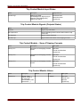
Trip Control Module – Sum of Tripping Currents..........................................................................................223
Trip Control Module Values..........................................................................................................................223
I-PROTECTION MODULE – OVERCURRENT PROTECTION
[ANSI 50, 51, 67]..............................................................................................................................224
Device Planning Parameters of the I Module...............................................................................................230
Global Protection Parameters of the I Module..............................................................................................230
Setting Group Parameters of the I Module...................................................................................................231
I Module Input States...................................................................................................................................234
I Module Signals (Output States).................................................................................................................235
Commissioning: Overcurrent Protection, non-directional [ANSI 50, 51].......................................................236
Commissioning: Overcurrent Protection, directional [ANSI 67]....................................................................238
IG-PROTECTION MODULE – GROUND FAULT [ANSI 50N, 51N, 67N]........................................................239
Device Planning Parameters of the Ground Fault Protection ......................................................................245
Global Protection Parameters of the Ground Fault Protection ....................................................................245
Setting Group Parameters of the Ground Fault Protection ..........................................................................246
MRA4 02.08 UK
Page 5
Ground Fault Protection Input States...........................................................................................................249
Ground Fault Protection Signals (Output States).........................................................................................249
Commisioning: Ground Fault Protection – non-directional [ANSI 50N, 51N]................................................250
Commissioning: Ground Fault Protection – directional [ANSI 50N, 51N, 67N].............................................250
THR-PROTECTION MODULE: THERMAL REPLICA [ANSI 49]........................................................................251
Direct Commands of the Thermal Overload Module....................................................................................253
Device Planning Parameters of the Thermal Overload Module....................................................................253
Global Protection Parameters of the Thermal Overload Module..................................................................254
Setting Group Parameters of the Thermal Overload Module.......................................................................255
Thermal Overload Module Input States........................................................................................................257
Signals of the Thermal Overload Signals (Output States)............................................................................257
Thermal Overload Module Values................................................................................................................258
Thermal Overload Module Statistics............................................................................................................258
Commissioning: Thermal Replica [ANSI 49]................................................................................................259
I2>-PROTECTION MODULE – UNBALANCED LOAD PROTECTION [ANSI 46].....................................................260
Device Planning Parameters of the Unbalanced Load Module ...................................................................263
Global Protection Parameters of the Unbalanced Load Module...................................................................263
Setting Group Parameters of the Unbalanced Load Module........................................................................264
Unbalanced Load Module Input States........................................................................................................266
Unbalanced Load Module Signals (Output States).......................................................................................266
Commissioning: Unbalanced Load Protection [ANSI 46].............................................................................267
IH2 MODULE – INRUSH.......................................................................................................................269
Device Planning Parameters of the Inrush Module......................................................................................270
Global Protection Parameters of the Inrush module.....................................................................................270
Setting Group Parameters of the Inrush Module..........................................................................................271
Inrush Module Input States..........................................................................................................................272
Inrush Module Signals (Output States)........................................................................................................272
Commissioning: Inrush................................................................................................................................273
V-PROTECTION MODULE – VOLTAGE PROTECTION [ANSI 27/59]................................................................274
Device Planning Parameters of the Voltage Protection Module ..................................................................277
Global Protection Parameters of the Voltage Protection Module .................................................................277
Setting Group Parameters of the Voltage Protection Module ......................................................................278
Voltage Protection Module Input States.......................................................................................................280
Voltage Protection Module Signals (Output States)......................................................................................280
Commissioning: Overvoltage Protection [ANSI 59]......................................................................................281
Commissioning: Undervoltage Protection [ANSI 27]....................................................................................282
VE-PROTECTION MODULE – RESIDUAL VOLTAGE [ANSI 59N]...................................................................283
Device Planning Parameters of the Residual Voltage Supervision Module..................................................285
Global Protection Parameters of the Residual Voltage Supervision Module................................................285
Setting Group Parameters of the Residual Voltage Supervision Module......................................................286
Residual Voltage Supervision Module Input States......................................................................................287
Residual Voltage Supervision Module Signals (Output States)....................................................................288
Commissioning: Residual Voltage Protection - Measured [ANSI 59N].........................................................289
Commissioning: Residual Voltage Protection - Calculated [ANSI 59N]........................................................290
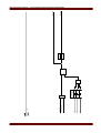
F-PROTECTION
MODULE – FREQUENCY PROTECTION [ANSI 81 O/U]...........................................................291
Device Planning Parameters of the Frequency Protection Module..............................................................293
Global Protection Parameters of the Frequency Protection Module.............................................................293
Setting Group Parameters of the Frequency Protection Module..................................................................294
Frequency Protection Module Input States..................................................................................................295
Frequency Protection Module Signals (Output States).................................................................................295
Commissioning: Frequency Protection (Overfrequency) [ANSI 81 O]..........................................................296
Commissioning: Frequency Protection (Underfrequency) [ANSI 81 U]........................................................296
AR-PROTECTION MODULE – AUTOMATIC RECLOSURE [ANSI 79] (OPTION)....................................................297
Direct Commands of the Automatic Reclosure Module................................................................................304
Device Planning Parameters of the Module Automatic Reclosure...............................................................304
Global Protection Parameters of the Module Automatic Reclosure..............................................................305
Setting Group Parameters of the Module Automatic Reclosure...................................................................306
Module Automatic Reclosure Input States...................................................................................................309
Module Automatic Reclosure Signals (Output States)..................................................................................310
Automatic Reclosure Module Values............................................................................................................311
Setting Group Parameters of the Start Functions and Fast Trip of the Module Automatic Reclosure...........312
Module Automatic Reclosure Fast Trip Signals (Output States)...................................................................315
Page 6
MRA4 02.08 UK
Setting Group Parameters of the AR Abort Functions..................................................................................316
AR Abort Functions......................................................................................................................................317
AR Start Functions.......................................................................................................................................318
Commissioning: Automatic Reclosure [ANSI 79].........................................................................................319
EXP PROTECTION MODULE – EXTERNAL PROTECTION................................................................................320
Device Planning Parameters of the Module External Protection..................................................................322
Global Protection Parameters of the Module External Protection.................................................................322
Setting Group Parameters of the Module External Protection......................................................................323
Module External Protection Input States......................................................................................................324
Module External Protection Signals (Output States)....................................................................................324
Commissioning: External Protection............................................................................................................325
CBF-SUPERVISION MODULE – CIRCUIT BREAKER FAILURE PROTECTION [ANSI 50BF]...................................326
Device Planning Parameters of the CBF Module.........................................................................................328
Global Protection Parameters of the CBF Module.......................................................................................328
Setting Group Parameters of the CBF Module.............................................................................................329
CBF Module Input States.............................................................................................................................330
CBF Module Signals (Output States)...........................................................................................................330
Commissioning: Circuit Breaker Failure Protection [ANSI 50BF].................................................................331
TCS-SUPERVISION MODULE – TRIP CIRCUIT SUPERVISION [74TC]..............................................................332
Device Planning Parameters of the Trip Circuit Supervision Module............................................................335
Global Protection Parameters of the Trip Circuit Supervision Module.........................................................335
Setting Group Parameters of the Trip Circuit Supervision Module...............................................................336
Trip Circuit Supervision Module Input States................................................................................................337
Trip Circuit Supervision Module Signals (Output States)..............................................................................337
Commissioning: Trip Circuit Supervision for Circuit Breakers [74TC]..........................................................338
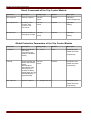
CTS-SUPERVISION MODULE – CURRENT TRANSFORMER SUPERVISION ...........................................................339
Device Planning Parameters of the Current Transformer Supervision.........................................................341
Global Protection Parameter of the Current Transformer Supervision.........................................................341
Setting Group Parameters of the Current Transformer Supervision.............................................................342
Current Transformer Supervision Input States.............................................................................................343
Current Transformer Supervision Signals (Outputs States).........................................................................343
Commissioning: Current Transformer Failure Supervision...........................................................................344
VTS-SUPERVISION MODULE - VOLTAGE TRANSFORMER SUPERVISION [ANSI 60FL]........................................345
Device Planning Parameters of the Voltage Transformer Module ...............................................................347
Global Protection Parameters of the Voltage Transformer Supervision Module ..........................................347
Setting Group Parameters of the Voltage Transformer Module....................................................................348
Voltage Transformer Supervision Module Input States................................................................................349
Voltage Transformer Module Signals (Output States)..................................................................................349
Commissioning: Voltage Transformer Supervision (via DI) [ANSI 60FL]......................................................350
Commissioning: Voltage Transformer Failure [ANSI 60FL]..........................................................................351
SYSTEM PARAMETERS..........................................................................................................................352
Date and Time.............................................................................................................................................352
Synchronize Date and Time via Smart View.........................................................................................352
Version.........................................................................................................................................................352
Version via Smart view.................................................................................................................................352
Direct Commands of the System Module.....................................................................................................353
Global Protection Parameters of the System...............................................................................................354
System Module Input States........................................................................................................................356
System Module Signals................................................................................................................................357
Special Values of the System Module..........................................................................................................358
COMMISSIONING .................................................................................................................................359
Commissioning/Protection Test ...................................................................................................................360
Putting out of Operation – Plug out the Relay..............................................................................................361
SELF SUPERVISION..............................................................................................................................362
Errormessages / -codes...............................................................................................................................363
TECHNICAL DATA ...............................................................................................................................364
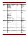
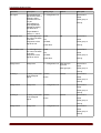
Climatic Environmental Conditions...............................................................................................................364
Routine Test.................................................................................................................................................364
Housing........................................................................................................................................................364
Plug-in Connectors with Integrated Short-Circuiter
(Conventional Current Inputs)..........................................................................................................................364
MRA4 02.08 UK
Page 7
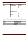
Voltage Supply.............................................................................................................................................365
Power Consumption.....................................................................................................................................365
Real Time Clock...........................................................................................................................................365
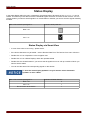
Display.........................................................................................................................................................365
Digital Inputs................................................................................................................................................366
Current and Earth Current Measurement.....................................................................................................367
Voltage and Residual Voltage Measurement................................................................................................367
Frequency Measurement ............................................................................................................................367
Binary Output Relays...................................................................................................................................367
Time Synchronization IRIG..........................................................................................................................368
Front Interface RS232..................................................................................................................................368
RS485..........................................................................................................................................................368
Boot phase...................................................................................................................................................368
STANDARDS.......................................................................................................................................369
Design Standards........................................................................................................................................369
High Voltage Tests (IEC 60255-6) ...............................................................................................................369
EMC Immunity Tests....................................................................................................................................369
EMC Emission Tests....................................................................................................................................370
Environmental Tests.....................................................................................................................................371
Mechanical Tests.........................................................................................................................................372
TOLERANCES......................................................................................................................................373
Real Time Clock Tolerances........................................................................................................................373
Measured Values Tolerances.......................................................................................................................373
Phase and Earth Current Measuring...................................................................................................373
Phase-to-earth and Residual Voltage Measurement................................................................................374
Frequency measurement..................................................................................................................374
Protection Stages Tolerances......................................................................................................................375
2a471fa926af4745072d0f83d0d296c3
0e3753f6c32da6855b57d4afbe254a34
RMS Handoff: 0
File: C:\p4_data\deliverMRA4\generated\MRA4_user_manual_uk.odt
Build: 4326
Version 1.1.d
Page 8
MRA4 02.08 UK
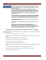
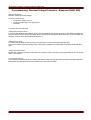
Comments on the Manual
Comments on the Manual
This manual explains in general the tasks of device planning, parameter setting, installation, commissioning,
operation and maintenance of the HighPROTEC devices.
The manual serves as working basis for:
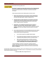
•
•
•
•
Engineers in the protection field,
commissioning engineers,
people dealing with setting, testing and maintenance of protection and control devices,
as well as trained personnel for electrical installations and power stations.
All functions concerning the type code will be defined. Should there be a description of any functions, parameters
or inputs/outputs which do not apply to the device in use, please ignore that information.
All details and references are explained to the best of our knowledge and are based on our experience and
observations.
This manual describes the (optionally) full featured versions of the devices.
All technical information and data included in this manual reflect their state at the time this document was issued.
We reserve the right to carry out technical modifications in line with further development without changing this
manual and without previous notice. Hence no claim can be brought based on the information and descriptions
this manual includes.
Text, graphic and formulae do not always apply to the actual delivery scope. The drawings and graphics are not
true to scale. We do not accept any liability for damage and operational failures caused by operating errors or
disregarding the directions of this manual.
No part of this manual is allowed to be reproduced or passed on to others in any form, unless Woodward SEG
GmbH & Co. KG have approved in writing.
This user manual is part of the delivery scope when purchasing the device. In case the device is passed on
(sold) to a third party, the manual has to be handed over as well.
Any repair work carried out on the device requires skilled and competent personnel who need to be well aware
especially of the local safety regulations and have the necessary experience for working on electronic protection
devices and power installations (provided by evidence).
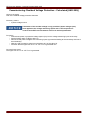
Information Concerning Liability and Warranty
Woodward SEG does not accept any liability for damage resulting from conversions or changes carried out on
the device or planning (projecting) work, parameter setting or adjustment changes done by the customer.
The warranty expires after a device has been opened by others than Woodward SEG specialists.
Warranty and liability conditions stated in Woodward SEG’s General Terms and Conditions are not
supplemented by the above mentioned explanations.
MRA4 02.08 UK
Page 9
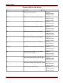
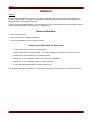
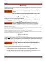
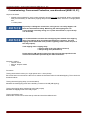
IMPORTANT DEFINITIONS
IMPORTANT DEFINITIONS
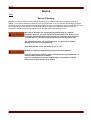
The signal definitions shown below serve the safety of life and limb as well as for the appropriate operating life of
the device.
DANGER indicates a hazardous situation which, if not avoided, will result in
death or serious injury.
WARNING indicates a hazardous situation which, if not avoided, could
result in death or serious injury.
CAUTION, used with the safety alert symbol, indicates a hazardous
situation which, if not avoided, could result in minor or moderate injury.
NOTICE is used to address practices not related to personal injury.
CAUTION, without the safety alert symbol, is used to address practices not
related to personal injury.
Page 10
MRA4 02.08 UK
IMPORTANT DEFINITIONS
FOLLOW INSTRUCTIONS
Read this entire manual and all other publications pertaining to the work to
be performed before installing, operating, or servicing this equipment.
Practice all plant and safety instructions and precautions. Failure to follow
instructions can cause personal injury and/or property damage.
PROPER USE
Any unauthorized modifications to or use of this equipment outside its
specified mechanical, electrical, or other operating limits may cause
personal injury and/or property damage, including damage to the
equipment. Any such unauthorized modifications: (1) constitute "misuse"
and/or "negligence" within the meaning of the product warranty thereby
excluding warranty coverage for any resulting damage, and (2) invalidate
product certifications or listings.
The progamable devices subject to this manual are designed for protection
and also control of power installations and operational devices. The
devices are further designed for installation in low-voltage (LV)
compartments of medium voltage (MV) switchgear panels or in decentralized protection panels. The programing and parameterization has to
meet all requirements of the protection concept (of the equipment that is to
be protected). You must ensure that the device will properly recognize and
manage (e.g. switch off the circuit breaker) on the basis of your progaming
and parameterization all operational conditions (failures). Before starting
any operation and after any modification of the programming
(parameterization) test make a documentary proof that your programing
and parameterization meets the requirements of your protection concept.
Typical applications for this product family/device line are for instance:
•
Feeder protection
•
Mains protection
•
Machine protection
Any usage beyond these applications the devices are not designed for. The
manufacturer cannot be held liable for any resulting damage, the user alone
bears the risk for this. As to the appropriate use of the device: The
technical data specified by Woodward SEG have to be met.
MRA4 02.08 UK
Page 11
IMPORTANT DEFINITIONS
OUT-OF-DATE PUBLICATION
This publication may have been revised or updated since this copy was
produced. To verify that you have the latest revision, be sure to check the
Woodward SEG documentation website:
doc.seg-pp.com
The latest version of most publications is available at: doc.seg-pp.com
If your publication is not there, please contact your customer service
representative to get the latest copy.
Page 12
MRA4 02.08 UK
IMPORTANT DEFINITIONS
Electrostatic Discharge Awareness
All electronic equipment is electro static-sensitive, some components more
than others. To protect these components from electro static damage, you
must take special precautions to minimize or eliminate electrostatic
discharges.
Follow these precautions when working with or near the control.
1.
Before doing maintenance on the electronic control, discharge the
static electricity on your body to ground by touching and holding a
grounded metal object (pipes, cabinets, equipment, etc.).
2.
Avoid the build-up of static electricity on your body by not wearing
clothing made of synthetic materials. Wear cotton or cotton-blend
materials as much as possible because these do not store static
electric charges as much as synthetics.
3.
Keep plastic, vinyl, and Styrofoam materials (such as plastic or
Styrofoam cups, cup holders, cigarette packages, cellophane
wrappers, vinyl books or folders, plastic bottles, and plastic ash trays)
away from the control, the modules, and the work area as much as
possible.
4.
Do not remove any printed circuit board (PCB) from the control cabinet
unless absolutely necessary. If you must remove the PCB from the
control cabinet, follow these precautions:
•
Do not touch any part of the PCB except the edges.
•
Do not touch the electrical conductors, the connectors, or the
components with conductive devices or with your hands.
•
When replacing a PCB, keep the new PCB in the plastic
antistatic protective bag it comes in until you are ready to
install it. Immediately after removing the old PCB from the
control cabinet, place it in the antistatic protective bag.
To prevent damage to electronic components caused by improper
handling, read and observe the precautions in Woodward manual 82715,
Guide for Handling and Protection of Electronic Controls, Printed Circuit
Boards, and Modules.
Woodward SEG reserves the right to update any portion of this publication at any time. Information provided by
Woodward SEG is believed to be correct and reliable. However, no responsibility is assumed by Woodward SEG
unless otherwise expressly undertaken.
© Woodward SEG 2007 All Rights Reserved
MRA4 02.08 UK
Page 13
IMPORTANT DEFINITIONS
Scope of Delivery
The delivery scope does not include the fastening material, but includes all connection terminals, except
communication connectors. Please check the consignment for completeness on arrival (delivery note).
Please ascertain whether the type plate, connection diagram, type code and description of the device tally.
If you have any doubts please contact our Service Department (contact address to be found on the reverse of
the manual).
Storage
The devices must not be stored outdoors. The storing facilities have to be sufficiently ventilated and must be dry
(see Technical Data).
Important Information
In line with the customer’s requirement the devices are combined in a
modular way (in compliance with the order code). The terminal assignment
of the device can be found on the top of the device (wiring diagram). In
addition to that it can be found within the appendix (wiring diagrams).
Page 14
MRA4 02.08 UK
MRA4 02.08 UK
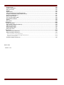
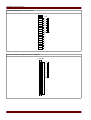
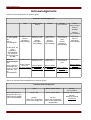
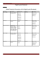
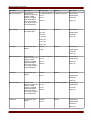
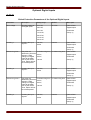
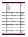
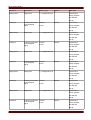
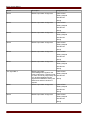
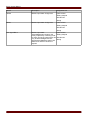
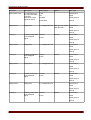
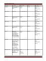
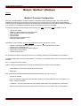
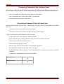
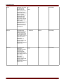
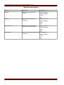
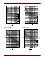
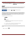
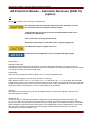
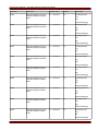
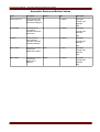
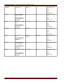
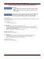
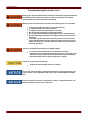
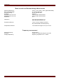
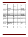
"φ "=Elements with complex functions
"gray-box".
Functional description: If the setting
value "IE.Block at VE=0" is set to
"inactive" the output 1 is active and
output 2 is inactive. If the setting value
"IE.Block at VE=0" is set to "active" the
output 2 is active and the output 1 is
inactive.
Measured values:
internal message
Signal:
Device Planning:
setting value:
φ
AR.t-DP
active
inactive
IG.nondir Trip at
VE=0
t-DP
IG
0
<name>.*int Alm L1
Prot.I dir fwd
<name>
<name>.I
2
1
Limit value monitoring with three
analogue input values. Compares 3
analogue values with the set limit;
output values are three different
binary values as a result of the
comparision. If the analogue signal
exceeds the limit I/In the
corresponding output signal becomes
"1".
Parameter of a Module-Input (with
special values): An (1..n) output from the
list will be assigned to the input
"<name>.identifier". If the parameter is
set to "ItemNull", an "active"-signal will be
given out.
Parameter of a Module-Input with a
SelectionList/DropDown. An (1..n)
signal/output from the list or a predefined value can be selcted.
option/features to be realised in the future
IL3
IL2
IL1
I/ In
no assignment,1..n
1..n,
1..n,
Assignment
VeEnableList
no assignment 1
<name>
1..n, Assignment List
<name>
active
inactive
TripControl.Latched
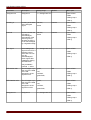
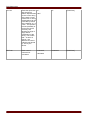
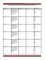
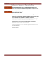
IMPORTANT DEFINITIONS
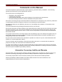
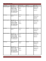
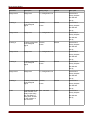
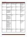
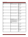
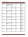
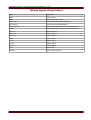
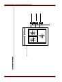
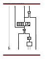
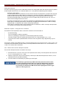
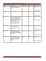
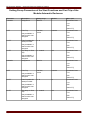
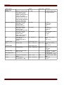
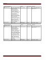
Symbols
Page 15
Page 16
Analogue values
comparator
analogue values
Quotient of analogue values
band-pass (filter)
IH2
band-pass (filter)
IH1
negated output
negated input
exclusive-OR
or
and
IH2
IH1
IH2
IH1
=1
>1
&
Time stage minimum pulse
width: The pulse width
<name>.t will be started if a
"1" is feed to the input. By
starting <name>.t the output
becomes "1". If the time is
expired, the output becomes
"0" independent from the
input signal.
edge triggered counter
+ increment
R Reset
Time stage: A "1" at the
input starts the stage. If the
time <name>.t is expired
the output becomes "1" too.
The time stage will be
reseted by "0" at the input.
Thus the output will be set to
"0" at the same time.
RS flip-flop
abcd
0 0 unchanged
0101
1010
1101
t
b
a
t
1
0
c
d
TripControl.t-TripCmd
R
+
1
R1
<name>.t
1
S
IMPORTANT DEFINITIONS
MRA4 02.08 UK
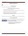
Device
Device
MRA4
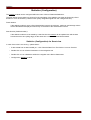
Device Planning
Planning of a device means to reduce the functional range to a degree that suits the protection task to be
fulfilled, i.e. the device shows only those functions you really need. If you, for example, deactivate the voltage
protection function, all parameter branches related to this function do not appear in the parameter tree any more.
All corresponding events, signals etc. will be deactivated too. By this the parameter trees become very
transparent. Planning also involves adjustment of all basic system data (frequency etc.).
But it has to be taken into account that by deactivating, for instance,
protective functions, you also change the functionality of the device. If you
cancel the directional feature of the overcurrent protections then the device
no longer trips in a directional way but merely in a non-directional way.
The manufacturer does not accept liability for any personal or material
damage as a result of wrong planning.
A planning service is also offered by Woodward SEG.
Beware of inadvertent deactivating protective functions/modules
If you are deactivating modules within the device planning all parameters of
those modules will be set on default.
If you are activating one of these modules again all parameters of those
reactivated modules will be set on default.
MRA4 02.08 UK
Page 17
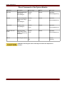
Device
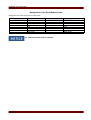
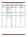
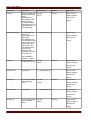
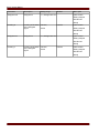
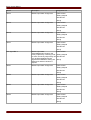
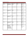
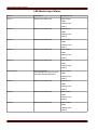
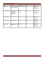
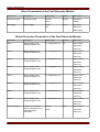
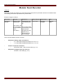
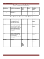
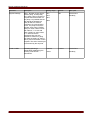
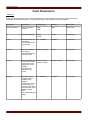
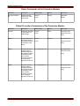
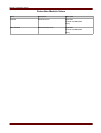
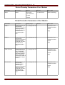
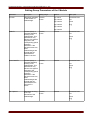
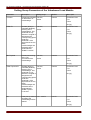
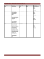
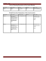
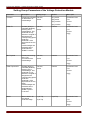
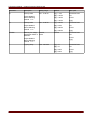
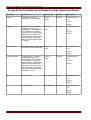
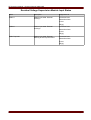
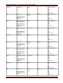
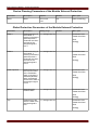
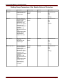
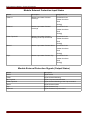
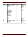
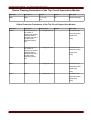
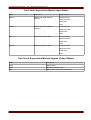
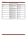
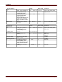
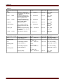
Device Planning Parameters of the Device
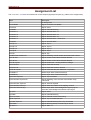
Parameter
Description
Options
Default
Menu path
Hardware variant 1
Optional hardware
extension
»A« 8 digital inputs |
6 binary output
relays,
8 digital inputs | 6
binary output relays
[MRA4]
»B« 16 digital inputs
| 6 binary output
relays,
»C« 8 digital inputs |
12 binary output
relays,
»D« 16 digital inputs
| 12 binary output
relays
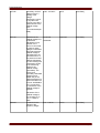
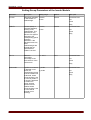
Hardware variant 2
Optional hardware
extension
»0« standard
standard
[MRA4]
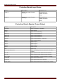
Housing
Mounting form
»A« Flush mounting
Flush mounting
[MRA4]
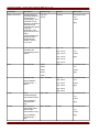
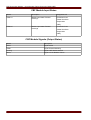
Protection extension Optional protection
1
extension
»0« without,
without
[MRA4]
Protection extension Optional protection
2
extension
»A« without
without
[MRA4]
Protection extension Optional protection
3
extension
»0« without
without
[MRA4]
Protection extension Optional protection
4
extension
»A« without
without
[MRA4]
Disturbance recorder Disturbance recorder »0« standard
standard
[MRA4]
Communication
without
[MRA4]
Communication
»1« AR
»A« without,
»G« Modbus RS485
D-Sub,
»H« Modbus RS485
terminal
Language package
Language package
»0« English-English, English-English
[MRA4]
»1« English-German
Page 18
MRA4 02.08 UK
Installation and Connection
Installation and Connection
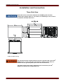
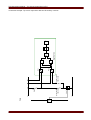
Three-Side-View
Dependent on the connection method of the SCADA system used the
needed space (depth) differs. If, for instance, a D-Sub-Plug is used, it has to
be added to the depth dimension.
3-Side-View B2 Housing
The housing must be carefully earthed. Connect a ground cable (4 to 6 mm2
(AWG 12-10) / 1.7 Nm (15 lb-in)) to the housing, using the screw, which is
marked with the ground symbol (at the rear side of the device).
The power supply card needs a separate ground connection (2.5 mm2
(AWG 14) at terminal X1 (0.55 Nm/4.9 lb-in).
MRA4 02.08 UK
Page 19
Installation and Connection
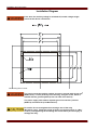
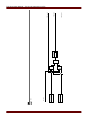
Installation Diagram
Even when the auxiliary voltage is switched-off, unsafe voltages might
remain at the device connections.
B2 Housing Door Cut-out
The housing must be carefully earthed. Connect a ground cable (4 to 6 mm2
(AWG 12-10) / 1.7 Nm (15 lb-in)) to the housing, using the screw, which is
marked with the ground symbol (at the rear side of the device).
The power supply card needs a separate ground connection (2.5 mm2
(AWG 14) at terminal X1 (0.55 Nm/4.9 lb-in).
Be careful. Do not overtighten the mountings nuts of the relay
(M4 metric 4 mm). Check the torque by means of a torque wrench (1.7 Nm /
15 lb-in). Overtightening the mounting nuts could due to personal injury or
damage the relay.
Page 20
MRA4 02.08 UK
Installation and Connection
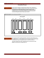
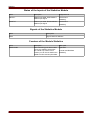
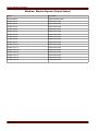
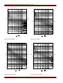
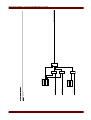
Assembly Groups
In line with the customer’s requirement the devices are combined in a
modular way (in compliance with the order code). In each of the slots an
assembly-group may be integrated. In the following the terminal
assignment of the individual assembly-groups are shown. The exact
installation place of the individual modules can be learned from the
connection diagram fixed at the top of your device.
Middle Housing B2 for the following device:MRA4
Housing B2
slot1
slot2
X1
X2
X100
slot3
slot4
slot5
slot6
X3
X4
X5
X6
X102
X103
X104
The housing must be carefully grounded. Connect a ground cable (4 to 6
mm2 (AWG 12-10) / 1.7 Nm (15 lb-in)) to the housing, using the screw, which
is marked with the ground symbol (at the rear side of the device).
The power supply card needs a separate ground connection (2.5 mm2
(AWG 14) at terminal X1 (0.55 Nm/4.9 lb-in).
MRA4 02.08 UK
Page 21
Installation and Connection
Grounding
The housing must be carefully grounded. Connect a ground cable (4 to 6
mm2 (AWG 12-10) / 1.7 Nm (15 lb-in)) to the housing, using the screw, which
is marked with the ground symbol (at the rear side of the device).
The power supply card needs a separate ground connection (2.5 mm2
(AWG 14) at terminal X1 (0.55 Nm/4.9 lb-in).
The devices are very sensitive to electro-static discharges.
Page 22
MRA4 02.08 UK
Installation and Connection
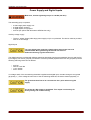
Power Supply and Digital Inputs
Make sure, that the tightening torque is 0.55 Nm (4.9 lb-in).
This assembly group comprises:
•
•
•
•
a wide-range power supply unit
6 digital inputs, grouped
2 digital inputs, non-grouped
24V DC (for options with Woodward SEG Devices only)
Auxiliary voltage supply
•
The aux. voltage inputs (wide-range power supply unit) is non-polarized. The device could be provided
with AC or DC voltage.
Digital inputs
For each digital input group the related voltage input range has to be
parameterized. Wrong switching thresholds can result in
malfunctions/wrong signal transfer times.
The digital inputs are provided with different switching thresholds (can be parameterized) (two AC and five DC
input ranges). For the six grouped (connected to common potential) inputs and the two non-grouped inputs the
following switching levels can be defined:
•
•
•
•
24V DC
48V DC / 60V DC
110 V AC/DC
230 V AC/DC
If a voltage >80% of the set switching threshold is applied at the digital input, the state change is recognized
(physically “1”). If the voltage is below 40% of the set switching threshold, the device detects physically “0”.
The ground terminal has to be connected to the »-pole« when using DC
supply.
Use of the 24 V DC Output is prohibited. This output is exclusively for
factory testing and commissioning.
MRA4 02.08 UK
Page 23
Installation and Connection
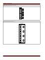
MRA4, MRU4, MRI4 Terminal Marking => X1
X?.
1
2
3
4
5
6
7
8
9
10
11
12
13
14
15
16
17
18
PE
L+ Power
L- Supply
n.c.
COM1
DI1
COM2
DI2
COM3
COM
DI3
DI4
DI5
DI6
DI7
DI8
24 V DC OUT1
COM OUT1
Electro-mechanical assignment
Page 24
1
PE
2
L+
3
L-
4
n.c.
5
COM1
6
DI1
7
COM2
8
DI2
9
COM3
18 17 16 15 14 13 12 11 10
0+HTL-NT
COM3
Power Supply
DI3
DI4
DI5
DI6
DI7
DI8
24 V DC OUT1
COM OUT1
MRA4 02.08 UK
Installation and Connection
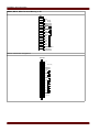
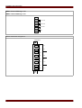
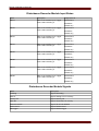
Binary Output Relays
The number of the binary output relay contacts is related to the type of the device or type code. The binary
output relays are potential-free change-over contacts. In chapter [Assignment/binary outputs] the assignment of
the binary output relays is specified. The changeable signals are listed in the »assignment list« which can be
found in the appendix.
Make sure that the tightening torque is 0.55 Nm (4.9 lb-in).
Please duly consider the current carrying capacity of the binary output
relays. Please refer to the Technical Data.
MRA4 02.08 UK
Page 25
Installation and Connection
Terminal Marking X5
for device: MRA4
Terminal Marking X2
for device: MRA4
X?.
1
2
3
4
5
6
7
8
9
10
11
12
13
14
15
16
17
18
X?.
1
2
3
4
5
6
7
8
9
10
11
12
13
14
15
16
17
18
BO1
BO2
BO3
BO4
BO5
BO6
BO1
BO2
BO3
BO4
BO5
BO6
Electro-mechanical assignment for device: MRA4
Page 26
1
BO1 n.c.
2
BO1 C
3
BO1 n.o.
4
BO2 n.c.
5
BO2 C
6
BO2 n.o.
7
BO3 n.c.
8
BO3 C
9
BO3 n.o.
18 17 16 15 14 13 12 11 10
0+HTL-MK
BO4 n.c.
BO4 C
BO4 n.o.
BO5 n.c.
BO5 C
BO5 n.o.
BO6 n.c.
BO6 C
BO6 n.o.
MRA4 02.08 UK
Installation and Connection
Digital Inputs
This module is provided with 8 grouped digital inputs.
In chapter [Device parameter/Digital Inputs] the assignment of the digital inputs is specified.
Make sure that the tightening torque is 0.55 Nm (4.9 lb-in).
The ground terminal has to be connected to the »-pole« when using DC
supply.
For each digital input group the related voltage input range has to be
parameterized. Wrong switching thresholds can result in
malfunctions/wrong signal transfer times.
Via the »assignment list« the states of the digital inputs are assigned to the
module inputs (e.g. I[1]).
The digital inputs are provided with different switching thresholds (can be parameterized) (two AC and five DC
input ranges). For each group the following switching thresholds can be defined:
•
•
•
•
24V DC
48V DC / 60V DC
110 V AC/DC
230 V AC/DC
If a voltage >80% of the set switching threshold is applied at the digital input, the state change is recognized
(physically “1”). If the voltage is below 40% of the set switching threshold, the device detects physically “0”.
MRA4 02.08 UK
Page 27
Installation and Connection
Terminal Marking X6 for device: MRA4
X?.
1
2
3
4
5
6
7
8
9
10
11
12
13
14
15
16
17
18
COM1
DI1
DI2
DI3
DI4
DI5
DI6
DI7
DI8
n.c.
n.c.
n.c.
n.c.
n.c.
n.c.
n.c.
n.c.
n.c.
Electro-mechanical assignment for device: MRA4
Page 28
1
COM1
2
DI1
3
DI2
4
DI3
5
DI4
6
DI5
7
DI6
8
DI7
18 17 16 15 14 13 12 11 10 9
0+HTL-DI-8
DI8
MRA4 02.08 UK
Installation and Connection
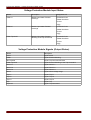
Voltage Measuring Inputs
The device is provided with 4 voltage measuring inputs: three for measuring the phase-to-phase voltages
(»V12«, »V23« , »V31«) or phase-to-neutral voltages (»VL1«, »VL2«, »VL3«) and one for the measuring of the
residual voltage »VE«. With the field parameters the correct connection of the voltage measuring inputs has to
be set:
•
•
phase-to-neutral (star)
phase-to-phase (Delta respectively V-Connection)
Make sure that the tightening torque is 1 Nm (8.85 lb-in).
The rotating field of your power supply system has to be taken in to
account. Make sure that the transformer is wired correctly.
For the V-connection the parameter »VT con« has to be set to »phase-tophase«.
Please refer to the Technical Data.
MRA4 02.08 UK
Page 29
Installation and Connection
MRA4 Terminal Marking => X4
MRU4 Terminal Marking => X3
X?.
1
2
3
4
5
6
7
8
VL1/VL12
VL2/VL23
VL3/VL31
VE
Electro-mechanical assignment
Page 30
1
VL1.1
2
VL1.2
3
VL2.1
4
VL2.2
5
VL3.1
6
VL3.2
7
VE1.1
8
0+HTL-TU-x
VE1.2
MRA4 02.08 UK
Installation and Connection
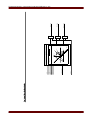
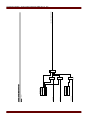
Current Measuring Inputs and Ground Current Measuring Input
The device is provided with 4 current measuring inputs: three for measuring the phase currents and one for
measuring of the earth current. Each of the current measuring inputs has a measuring input for 1 A and 5 A.
The input for earth current measuring either can be connected to a cable-type current transformer or
alternatively it is possible to connect the summation current path of the phase current transformer to this input
(Holmgreen connection).
Current transformers have to be earthed on their secondary side.
Interrupting the secondary circuits of current transformers causes
hazardous voltages.
The secondary side of the current transformers have to be short circuited
before the current circuit to the device is opened.
The current measuring inputs may exclusively be connected to current
measuring transformers.
•
Do not interchange the inputs (1 A/5 A)
•
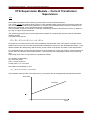
Make sure the transformation ratios and the power of the CTs are
correctly rated. If the rating of the CTs is not right (overrated), then
the normal operational conditions may not be recognized. The
pickup value of the measuring unit amounts approx. 3% of the rated
current of the device. Also the CTs need a current greater than
approx 3% of the rated current to ensure sufficient accuracy.
Example: For a 600 A CT (primary current) any currents below 18 A
cannot be detected any more.
•
Overloading can result in destruction of the measuring inputs or
faulty signals. Overloading means that in case of a short-circuit the
current-carrying capacity of the measuring inputs could be
exceeded.
Make sure, that the tightening torque is 1 Nm (11.94 lb-in).
MRA4 02.08 UK
Page 31
Installation and Connection
MRA4, MRI4 Terminal Marking => X3
X?.
1
2
3
4
5
6
7
8
9
10
11
12
1A
5A
IL1
N
1A
5A
IL2
N
1A
5A
IL3
N
1A
5A
IG
N
Electro-mechanical assignment
0+HTL-TI-x
IL1-1A
IL1-5A
2
IL2-1A
4
IL2-5A
5
IL3-1A
7
IL3-5A
8
IG-1A
10
IG-5A
Page 32
1
3
IL1-N
6
IL2-N
9
IL3-N
12
IG-N
11
MRA4 02.08 UK
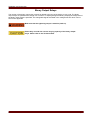
Installation and Connection
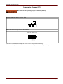
Supervision Contact (SC)
Make sure that the tightening torque is 0.55 Nm (4.9 lb-in).
1
2
3
4
5
X104
SC
Terminal markings X104 for device: MRA4
Electro-mechanical assignment for device: MRA4
0+HTL-uP-6 / 0+HTL-uP-14
C
SC
SC n.o.
SC n.c.
X104
1 2 3 4 5
This contact closes after the boot phase of the device if the protection is working.
This contact will open if an internal device error has occurred (please refer to chapter Self Supervision).
MRA4 02.08 UK
Page 33
Installation and Connection
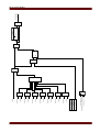
Communication Interfaces
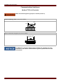
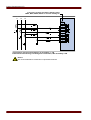
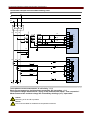
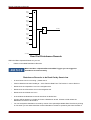
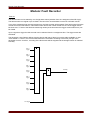
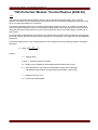
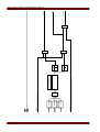
Modbus® RTU via Terminals
Make sure that the tightening torque is 0.23 Nm (2.03 lb-in).
Terminal Marking X103 for the device: MRA4
P
P
1
2
3
4
5
6
X102
N
120Ω
GND
560Ω
N
+5V
560 Ω
Electro-mechanical assignment for device: MRA4
N
P
N
P
+5V R1 = 560 ΩGND
R2 = 120 Ω
R1
R1
R2
1 2 3 4 5 6
The Modbus® connection cable must be shielded. The shielding has to be
fixed at the screw which is marked with the ground symbol at the rear side
of the device.
Page 34
MRA4 02.08 UK
Installation and Connection
Modbus® RTU via D-SUB-plug
Terminal marking X103 for the device: MRA4
6
1
9
5
Electro-mechanical assignment for device: MRA4
D-SUB assignment - bushing
1 Earthing/shielding
3 RxD TxD - P: High-Level
4 RTS-signal
5 DGND: Ground, neg. Potential of aux voltage
supply
6 VP: pos. Potential of the aux voltage supply
8 RxD TxD - N: Low-Level
The Modbus® connection cable must be shielded. The shielding has to be
fixed at the screw which is marked with the ground symbol at the back side
of the device.
MRA4 02.08 UK
Page 35
Installation and Connection
PC Interface
X120 9-pole D-Sub at all device fronts
B1, B2 und B3 Housing
RS232 PC-Interface
for Parameter Setting
and Evaluation
Software - X120
Electro-mechanical assignment for all device types
1
6
5
9
1 DCD
2 RxD
3 TxD
4 DTR
5 GND
6 DSR
7 RTS
8 CTS
9 RI
housing shielded
Page 36
MRA4 02.08 UK
Installation and Connection
Assignment of the Zero Modem Cable
Assignment of the fully wired zero modem cable
Dsub -9 (female)
2
3
4
6,1
7
8
5
9
Signal
RxD
TxD
DTR
DSR, DCD
RTS
CTS
GND (Ground)
Ring signal
Dsub -9 (female)
3
2
6,1
4
8
7
5
9
Signal
TxD
RxD
DSR, DCD
DTR
CTS
RTS
GND (Ground)
Ring signal
The connection cable must be shielded.
MRA4 02.08 UK
Page 37
Current Transformers (CT)
Current Transformers (CT)
Check the installation direction.
It is imperative that the secondary sides of measuring transformers be
grounded.
CT secondary circuits must always to be low burdend or short-circuited
during operation.
All current measuring inputs can be provided with 1 A or 5 A nominal. Make
sure that the wiring is correct.
Current Transformer Connection Examples
Connection example Clockwise Rotating Field
MRI4, MCI4, MRA4, MCA4 => teminal marking X3.
L1
L2
L3
IL1'
IL2'
IL1
IL3'
IL2
X3.
1
2
3
4
5
6
7
8
9
10
11
12
1A
5A
IL1
N
1A
5A
IL2
N
1A
5A
IL3
N
1A
5A
IG
N
IL3
Three phase current measurement; In secondary = 5 A
Notice!
Calculation of IE is possible
Page 38
MRA4 02.08 UK
Current Transformers (CT)
Connection example Clockwise Rotating Field
MRI4, MCI4, MRA4, MCA4 => teminal marking X3.
L1
L2
L3
IL1'
IL2'
IL1
IL3'
IL2
IE'
X3.
1
2
3
4
5
6
7
8
9
10
11
12
1A
5A
IL1
N
1A
5A
IL2
N
1A
5A
IL3
N
1A
5A
IG
N
IL3
Three phase current measurement; In secondary = 1 A;
Earth-current measuring via cable-type current transformer ; IEn secondary = 1 A
Warning!
The shielding at the dismantled end of the line has to be put through the cable-type current
transformer and has to be grounded at the cable side.
Notice!
Recommendated for isolated or compensated networks
MRA4 02.08 UK
Page 39
Current Transformers (CT)
Connection example Clockwise Rotating Field
MRI4, MCI4, MRA4, MCA4 => teminal marking X3.
L1
L2
L3
X3.
IL1'
IL1'
IL2'
IL1
IL2'
IL3'
IL2
IL3'
IG'
1
2
3
4
5
6
7
8
9
10
11
12
1A
5A
IL1
N
1A
5A
IL2
N
1A
5A
IL3
N
1A
5A
IG
N
IL3
Three phase current measurement; In secondary = 5 A
Earth-current measuring via Holmgreen-connection; IEn secondary = 5A
Notice!
Not recommendated for isolated and compensated networks
Page 40
MRA4 02.08 UK
Current Transformers (CT)
Connection example Clockwise Rotating Field
MRI4, MCI4, MRA4, MCA4 => teminal marking X3.
L1
L2
L3
IL1'
IL1'
IL2'
IL1
IL2'
IL3'
IL3'
IL2
IG'
X3.
1
2
3
4
5
6
7
8
9
10
11
12
1A
5A
IL1
N
1A
5A
IL2
N
1A
5A
IL3
N
1A
5A
IG
N
IL3
Three phase current measurement; In secondary = 1 A
Earth-current measuring via Holmgreen-connection; IEn secondary = 1 A
Notice!
Not recommendated for isolated and compensated networks
MRA4 02.08 UK
Page 41
Current Transformers (CT)
Connection example Clockwise Rotating Field
MRI4, MCI4, MRA4, MCA4 => teminal marking X3.
L1
L2
L3
IL1'
IL1'
IL1
IL2'=-üIL2
IL3'
IL2
IL3'
IG'
X3.
1
2
3
4
5
6
7
8
9
10
11
12
1A
5A
IL1
N
1A
5A
IL2
N
1A
5A
IL3
N
1A
5A
IG
N
IL3
Two phase current measurement (V-connection); In secondary = 5 A
Earth-current measuring via cable-type current transformer ; IEn secondary = 5 A
Warning!
The shielding at the dismantled end of the line has to be put through the cable-type current
transformer and has to be grounded at the cable side.
Notice!
Recommendated for isolated or compensated networks
Page 42
MRA4 02.08 UK
Current Transformers (CT)
Connection example Anti-Clockwise Rotating Field
MRI4, MCI4, MRA4, MCA4 => teminal marking X3.
L1
L3
L2
X3.
IL1'
IL1'
IL3'
IL1
IL3'
IL2'
IL2'
IL3
IG'
1
2
3
4
5
6
7
8
9
10
11
12
1A
5A
IL1
N
1A
5A
IL3
N
1A
5A
IL2
N
1A
5A
IG
N
IL2
Three phase current measurement; In secondary = 1 A
Earth-current measuring via Holmgreen-connection; IEn secondary = 1 A
Notice!
Not recommendated for isolated and compensated networks
MRA4 02.08 UK
Page 43
Voltage Transformers
Voltage Transformers
Check the installation direction of the VTs.
It is imperative that the secondary sides of measuring transformers be
grounded.
Check of the Voltage Measuring Values
Connect a three-phase measuring voltage equal to the rated voltage to the relay.
Take connection of the measuring transformers (star connection/delta
connection) duly into account.
Now adjust voltage values in the nominal voltage range with the corresponding nominal frequency which are not
likely to cause overvoltage- or undervoltage trips.
Compare the values shown in the device display with the readings of the measuring instruments. The deviation
must be according to the technical data.
When r.m.s. value measuring instruments are used, higher deviations can
arise if the fed voltage has a very high harmonic content. Since the device
is provided with a filter for the harmonics, only the fundamental oscillation
is evaluated (exception: thermal protection functions). If, however, a r.m.s.
value forming measuring instrument is used, the harmonics are also
measured.
Page 44
MRA4 02.08 UK
Voltage Transformers
Wiring Examples of the Voltage Transformers
Connection example Clockwise Rotating Field
MRA, MCA => teminal marking X4.
MRN4, MRU4, MRF4 => teminal marking X3.
L1
L2
L3
L1
V31'
V12'
L2
V23'
V12
L3
N
VL1' VL2' VL3'
V23
V31
X?.
1
2
3
4
5
6
7
8
VL1/
VL12
VL2/
VL23
VL3/
VL31
VE
VL1
VL2
VL3
Three-phase voltage measurement - wiring of the measurement inputs:
"star-connection"
Notice!
Calculation of the residual voltage VE is possible
MRA4 02.08 UK
Page 45
Voltage Transformers
Connection example Clockwise Rotating Field
MRA, MCA => teminal marking X4.
MRN4, MRU4, MRF4 => teminal marking X3.
L1
L2
L3
L1
V31'
V12'
L2
V23'
L3
V12
N
VL1' VL2' VL3'
V23
e
V31
VE'
n
X?.
1
2
3
4
5
6
7
8
VL1/
VL12
VL2/
VL23
VL3/
VL31
VE
VL1
VL2
VL3
Three-phase voltage measurement - wiring of the measurement inputs: "starconnection"
Measurement of the residual voltage VE via auxilliary windings (e-n) "open delta"
Page 46
MRA4 02.08 UK
Voltage Transformers
Connection example Clockwise Rotating Field
MRA, MCA => teminal marking X4.
MRN4, MRU4, MRF4 => teminal marking X3.
L1
L2
L3
L1
V31'
V12'
L2
V23'
L3
V12
V23
V31
X?.
1
2
3
4
5
6
7
8
VL1/
VL12
VL2/
VL23
VL3/
VL31
VE
VL1
VL2
VL3
Three-phase voltage measurement - wiring of the measurement inputs:
"delta connection"
Notice!
Calculation of the residual voltage VE is not possible
MRA4 02.08 UK
Page 47
Voltage Transformers
Connection example Clockwise Rotating Field
MRA, MCA => teminal marking X4
MRN4, MRU4, MRF4 => teminal marking X3
L1
L2
L3
L1
V31'
V12'
L2
V23'
L3
V12
V23
e
V31
VE'
n
X?.
1
2
3
4
5
6
7
8
VL1/
VL12
VL2/
VL23
VL3/
VL31
VE
VL1
VL2
VL3
Three-phase voltage measurement - wiring of the measurement inputs: "delta
connection"
Measurement of the residual voltage VE via auxilliary windings (e-n) "open delta"
Page 48
MRA4 02.08 UK
Voltage Transformers
Connection example Clockwise Rotating Field
MRA, MCA => teminal marking X4
MRN4, MRU4, MRF4 => teminal marking X3
L1
L2
L3
L1
V31'
V12'
L2
V23'
L3
V12
V23
e
V31
VE'
n
X?.
1
2
3
4
5
6
7
8
VL1/
VL12
VL2/
VL23
VL3/
VL31
VE
VL1
VL2
VL3
Three-phase voltage measurement - wiring of the measurement inputs: "delta
connection"
Measurement of the residual voltage VE via auxilliary windings (e-n) "open delta"
MRA4 02.08 UK
Page 49
Voltage Transformers
Connection example Clockwise Rotating Field
MRA, MCA => teminal marking X4.
MRN4, MRU4, MRF4 => teminal marking X3.
L1
L2
L3
L1
V31'
V12'
L2
V23'
L3
V12
V23
V31
X?.
1
2
3
4
5
6
7
8
VL1/
VL12
VL2/
VL23
VL3/
VL31
VE
Two-phase voltage measurement - wiring of the measuring
inputs: "V-connection"
Notice!
Calculation of the residual voltage VE is not possible
Page 50
MRA4 02.08 UK
Connection Examples Voltage and Current Transformers
Connection Examples Voltage and Current Transformers
Connection example Clockwise Rotating Field
L3
L2
L1
L1
L2
L3
L1
V31'
V12'
L2
V23'
L3
V12
N
VL1' VL2' VL3'
V23
e
V31
VE'
n
X4.
1
2
3
4
5
6
7
8
VL1/
VL12
VL2/
VL23
VL3/
VL31
VE
VL1
VL2
VL3
L1
L2
L3
IL1'
IL1'
IL2'
IL2'
IL3'
IL3'
IG'
IL1
IL2
X3.
1
2
3
4
5
6
7
8
9
10
11
12
1A
5A
IL1
N
1A
5A
IL2
N
1A
5A
IL3
N
1A
5A
IG
N
IL3
Three phase current measurement; In secondary = 1 A
Earth-current measuring via Holmgreen-connection; IEn secondary = 1 A
Three-phase voltage measurement - wiring of the measurement inputs: "star-connection"
Measurement of the residual voltage VE via auxilliary windings (e-n) "open delta"
Notice!
Measuring of VE and IE is possible
Notice!
Not recommendated for isolated and compensated networks
MRA4 02.08 UK
Page 51
Connection Examples Voltage and Current Transformers
Connection example Clockwise Rotating Field
L3
L2
L1
L1
L2
L1
L3
V31'
V12'
V12
V23
L2
V23'
L3
V31
L1
L2
X4.
1
2
3
4
5
6
7
8
VL1/
VL12
VL2/
VL23
VL3/
VL31
VE
L3
X3.
IL1'
IL1'
IL1
IL2'=-üIL2
IL3'
IL2
IL3'
IG'
1
2
3
4
5
6
7
8
9
10
11
12
1A
5A
IL1
N
1A
5A
IL2
N
1A
5A
IL3
N
1A
5A
IG
N
IL3
Two-phase voltage measurement - wiring of the measuring inputs: "V-connection"
Two phase current measurement (V-connection); In secondary = 5 A
Earth-current measuring via cable-type current transformer ; IEn secondary = 5 A
Warning!
The shielding at the dismantled end of the line has to be put through the cable-type current
transformer and has to be grounded at the cable side.
Notice!
Recommendated for isolated or
compensated networks
Page 52
Notice!
Calculation of the residual voltage VE is not
possible
MRA4 02.08 UK
Connection Examples Voltage and Current Transformers
Connection example Anti-Clockwise Rotating Field
L2
L3
L1
L1
L3
L2
L1
V21'
V13'
L3
V32'
L2
N
VL1' VL3' VL2'
e
VE'
n
X4.
1
2
3
4
5
6
7
8
VL1/
VL12
VL2/
VL23
VL3/
VL31
VE
VL1
VL3
VL2
L1
L3
L2
IL1'
IL1'
IL3'
IL3'
IL2'
IL2'
IG'
IL1
IL3
X3.
1
2
3
4
5
6
7
8
9
10
11
12
1A
5A
IL1
N
1A
5A
IL3
N
1A
5A
IL2
N
1A
5A
IG
N
IL2
Three phase current measurement; In secondary = 1 A
Earth-current measuring via Holmgreen-connection; IEn secondary = 1 A
Three-phase voltage measurement - wiring of the measurement inputs: "star-connection"
Measurement of the residual voltage VE via auxilliary windings (e-n) "open delta"
Notice!
Measuring of VE and IE is possible
Notice!
Not recommendated for isolated and compensated networks
MRA4 02.08 UK
Page 53
Navigation - Operation
Navigation - Operation
1
2
3
4
5
6
Page 54
7
8
9
MRA4 02.08 UK
Navigation - Operation
1
LEDs group A (left) Messages inform you about
operational conditions, system
data or other device particulars.
They additionally provide you
with information regarding
failures and functioning of the
device as well as other states
of the device and the
equipment.
Alarm signals can be freely
allocated to LEDs out of the
»assignment list«.
An overview about all alarm
signals available in the device
can be obtained from the
»ASSIGNMENT LIST« which can be
found in the appendix.
LED »System OK«
Should LED »System OK«
flash red during operation,
contact the Service Dept.
immediately.
3
Display
Via the display you can readout operational data and edit
parameters.
4
LEDs group B
(right)
Messages inform you about
operational conditions, system
data or other device particulars.
They additionally provide you
with information regarding
failures and functioning of the
device as well as other states
of the device and the
equipment.
Alarm signals can be freely
allocated to LEDs out of the
»assignment list« .
An overview about all alarm
signals available in the device
can be obtained from the
»assignment list« which can be
found in the appendix.
MRA4 02.08 UK
Page 55
Navigation - Operation
5
Softkeys
The function of the
»SOFTKEYS« are contextual.
On the bottom line of the
display the present function is
displayed/symbolized.
Possible functions are:
6
•
Navigation
•
Parameter
decrement/increment.
•
Scrolling up/down a menu
page
•
Moving to a digit
•
Change into the parameter
setting mode »wrench
symbol«.
INFO Key
Looking through the present
(Signals/Messages) LED assignment. The direct
select key can be actuated at
any time.
If the INFO key is actuated
once, the »LEFT LED SIGNALS«
are inserted, if the INFO key is
actuated again, the »RIGHT LED
SIGNALS« are inserted.
Multiple Assignments
If there is more than one signal
assigned to a LED you can
check the state of the multiple
assignments if you proceed as
follows.
If the INFO-Button is pressed
only the first assignments of
any LED is shown.
In order to show all (multiple)
assignments select a LED by
means of the »SOFTKEYs«
»up« and »down«
Via the »Softkey« »left« call up
a Submenu of this LED that
gives you detailed information
on the state of all signals
assigned to this LED.
Via the »C-key« you can call up
the reset menu.
Page 56
MRA4 02.08 UK
Navigation - Operation
7
»C Key«
To abort changes and to acknowledge messages.
In order to reset please press
the Softkey »wrench« and
enter the password.
The reset menu can be left by
pressing the Softkey »Arrowleft«
8
RS232 Interface
(Smart view
Connection)
Connection to software Smart
view is done via the RS232
interface.
9
»OK Key«
When using the »OK« key
parameter changes are
temporarily stored. If the »OK«
key is pressed again, those
changes are stored definitely.
MRA4 02.08 UK
Page 57
Navigation - Operation
Basic Menu Control
The graphic user interface is equivalent to a hierarchical structured menu tree. For access to the individual
submenus the »SOFTKEYS«/Navigation Keys are used. The function of the »SOFTKEYS« can be found as
symbol in the footer of the display.
Softkey
Description
•
Via »SOFTKEY« »up« you will come to the prior menu point/one parameter up by scrolling
upwards.
•
Via »SOFTKEY« »left« you will go one step back.
•
Via »SOFTKEY« »down« you will change to the next menu point/one parameter down by
scrolling downwards.
•
Via »SOFTKEY« »right« you will come to a submenu.
•
Via »SOFTKEY« »Top of list« you will jump directly to the top of a list.
•
Via »SOFTKEY« »Bottom of list« you will jump directly to the end of a list.
•
Via »SOFTKEY« »+«the related digit will be incremented. (Continuous pressure -> fast).
•
Via »SOFTKEY« »-«the related digit will be decremented. (Continuous pressure -> fast)
•
Via »SOFTKEY« »left« you will go one digit to the left.
•
Via »SOFTKEY« »right« you will go one digit to the right.
•
Via »SOFTKEY« »Parameter setting« you will call up the parameter setting mode.
•
Via »SOFTKEY« »delete« data will be deleted.
In order to return to the main menu, just keep pressing the Softkey »Arrow-Left« until you arrive at the »main
menu».
Page 58
MRA4 02.08 UK
Navigation - Operation
Smart view Keyboard Commands
You can control Smart view alternatively by means of keyboard commands (instead of the mouse)
Key
Description
á
Moving up within the navigation tree or parameter list.
â
Moving down within the navigation tree or parameter list.
ß
Collapse the tree item or select a folder on a higher level.
à
Expands the tree item or selects a subfolder.
Numpad +
Expands the tree item.
Numpad -
Collapses the tree item.
Home
Moves to the top of the active window.
End
Moves to the bottom of the active window.
Ctrl+O
Opens the file opening dialog. Browsing through the file system for an existing device
file.
Ctrl+N
Creates a new parameter file file by means of a template.
Ctrl+S
Saves actual loaded parameter file.
F1
Displays the online help information.
F2
Load Device Data
F5
Reloads the displayed data of a device.
Ctrl+F5
Enables automatic refresh.
Ctrl+Shift+T
Back to the navigation window.
Ctrl+F6
Walks through the tabular forms (detail windows).
Page á
Previous value (parameter setting).
Page â
Next value (parameter setting).
MRA4 02.08 UK
Page 59
Smart View
Smart View
Smart view is a parameter setting and evaluation software.
Menu-controlled parameter setting incl. validity checks
Offline configuration of all relay types
Reading and evaluating of statistical data and measuring values
Setting into operation assistance
Display of the device status
Fault analysis via event- and fault recorder
•
•
•
•
•
•
Smart view is available in two different versions (with and without Data
Visualizer (optionally/to analyze disturbance records).
•
•
Basic Edition
Standard Edition (option to analyze disturbance records)
Installation of Smart View
Port 52152 must not be blocked by a Firewall
If the Windows Vista User Access Control pops up while installing Smart
view, please “Allow” all installation requirements concerning Smart view.
System requirements:
Windows 2000 or compatible (e.g. Windows XP or Vista)
•
Double-click on the installation file with the left mouse button.
•
Select a language for the installation procedure.
•
Confirm by pressing the »Continue« button in the INFO frame.
•
Select an installation path or confirm the standard installation path by mouse click on the »Continue«
button.
•
Confirm the entry for the suggested installation folder by mouse click on the »Continue« button.
•
By mouse click on the »Install« button, the installation routine is started.
•
Close the installation procedure by mouse click on the »Complete« button.
Now you can call up the program via [Start>Programs>Woodward SEG>HighPROTEC>Smart view].
Uninstalling Smart view
Via the menu [Start>System Control >Software] the Smart view can be removed from your computer.
Page 60
MRA4 02.08 UK
Smart View
Switching the Language of the Graphical User Interface
Within the menu Settings/Language, you can change the language of the graphical user interface.
MRA4 02.08 UK
Page 61
Smart View
Setting up the Connection PC - Device
Set-up a Connection via Serial Interface under Windows 2000
After installation of the software, the »Connection PC/Notebook to the Device« has to be configured once, so
that you are able to read device data or re-write them into the device by means of the software Smart view.
For connection of your PCs/notebooks with the device you need a special
zero-modem cable (no serial cable!/please refer to chapter »Zero Modem
Cable«).
If your PC/notebook does not have a serial interface, you need a special
USB-to-serial-adapter. Only if the USB-to-serial-adapter is correctly
installed - aided by the provided CD – the communication with the device
can be established. (see next chapter).
The connection Notebook/PC to the device must not be
protected/encrypted via a smartcard.
If the network connection wizard asks you, to encrypt the connection via a
smartcard or not, please choose »Do not use the smartcard«.
Setting up/Configuring the connection
•
Connect your PC/notebook with the device via a zero-modem cable.
•
Start the software Smart view.
•
Select the menu point »Device Connection« in menu »Settings«.
•
Click on »Serial Connection«.
•
Click button »Settings«.
•
When initially setting up the connection, a dialogue window appears with the information that, so far, a
direct connection with your protection device has not been established. Click on »Yes«.
•
If, so far, a location has not been set up on your PC, your location information has to be put in. Confirm
the pop-up window »Telephone and Modem Options« with »OK«.
•
The Windows network connection assistant appears after the location information is set up. Select the
connection type »Establish direct connection to another computer«.
•
Select the serial interface (COM-Port) where the device shall be connected to.
•
Select »To be used for all users« in window »Availability of the connection«.
•
Do not change the connection name appearing in window »Name of the connection« and click the button
»Complete«.
•
Finally you arrive again in window »Device Installation« from where you started establishing the
connection. Confirm the adjustments by clicking the »OK« button.
Page 62
MRA4 02.08 UK
Smart View
Due to an bug in Windows 2000 it is possible that the automatically made
communication settings are not correctly adopted. In order to overcome
this problem, proceed as follows after setting up the serial connection:
MRA4 02.08 UK
•
Select menu point »Device Connection« in menu »Settings«.
•
Select »Serial Connection«.
•
Click button »Settings«.
•
Change to register card »General«.
•
Ensure that »Communication cable between two computers Com X
is selected in the »Drop Down Menu«. X = interface number where
you have connected the zero-modem cable to.
•
Click button »Configure«.
•
Ensure that the »Hardware Flowing Control« is activated.
•
Ensure that baud rate »115200« is selected.
Page 63
Smart View
Set up a Connection via Serial Interface under Windows XP
After installation of the software, the »Connection PC/Notebook to the Device« has to be configured once so that
you are able to read device data or re-write them into the device by means of the software Smart view.
For connection of your PCs/notebooks with the device, you need a zeromodem cable (no serial cable!/please refer to chapter »Zero Modem
Cable«).
If your PC/notebook does not have a serial interface, you need a special
»USB-to-serial-adapter«. Only if the »USB-to-serial-adapter« is correctly
installed - aided by the provided CD – the communication with the device
can be established. (see next chapter).
Setting up/Configuring the connection
•
Connect your PC/notebook with the device via a zero-modem cable.
•
Start the software Smart view.
•
Select the menu point »Device Connection« in menu »Settings«.
•
Click on »Serial Connection«.
•
Click button »Settings«.
•
When initially setting up the connection, a dialogue window appears with the information that, so far, a
direct connection with your protection device has not been established. Click on »Yes«.
•
If, so far, a location has not been set up on your PC, your location information has to be put in. Confirm
the following pop-up window »Telephone and Modem Options« with »OK«.
•
The Windows network connection assistant appears after the location information is set up. Select the
connection type »Establish direct connection to another computer«.
•
Select the serial interface (COM-Port) where the device shall be connected to.
•
Select »To be used for all users« in window »Availability of the connection«.
•
Do not change the connection name appearing in window »Name of the connection« and click the button
»Complete«.
•
Finally you arrive again in window »Device Installation« from where you started establishing the
connection. Confirm the adjustments by clicking the »OK« button.
Page 64
MRA4 02.08 UK
Smart View
Set up a Connection via Serial Interface under Windows Vista
Establishing the connection between Smart view and the device is a three step procedure.
1. Installing Smart view (the application itself)
2. Installing a (virtual) modem (that is a precondition for TCP/IP communication via a zero-modem cable)/
(to be done within the control panel).
3. Establishing a network connection between Smart view and the device
(to be done within Smart view).
1. Installlation of Smart view (the application itself).
Please see above.
2. Installation of the (virtual) modem
•
Call up the »Control Panel«
•
Choose »Hardware & Sound«
•
Choose »Phone & Modem Options«
•
Go to Tab »Modem«
•
Click on the »Add« button
•
A new window Install new modem pops up
•
Set the check box Don´t detect my modem
•
Choose» I will select from list«
•
Click on the »Next« button
•
Choose the correct COM-Port
•
Click on the »Next« button
•
Select Computer cable between two computers
•
Click on the »Properties« button
•
Go to Tab »General«
•
Click on the »Change Settings« button
•
Go to Tab »Modem«
•
Set within the Drop-Down Menu the correct baud rate = 115200
•
Click on the »OK« button
•
Click on the »OK« button
•
You have to reboot your computer now!
MRA4 02.08 UK
Page 65
Smart View
3. Establishing a network connection between Smart view and the device
•
Connect the device to the PC/notebook via a correct Zero-Modem-Cable.
•
Run Smart view.
•
Call up »Device Connection« within the menu »Device Connection«.
•
Click on the »Settings« button.
•
A wizard will pop up asking you How do you want to connect.
•
Choose »Dial-up«.
•
The Telephone number must not be empty. Please enter any number (e.g. 1).
•
Don´t care about the username and password.
•
Click on the »OK« button.
Page 66
MRA4 02.08 UK
Smart View
Connected to the Device and Calling up Websites at the same Time
In principle, it is possible to call up websites while there is an active connection to the device.
If your computer has no direct connection to the internet, that means, that it is placed behind a proxy server, the
device connection has to be modified in certain circumstances. The device connection has to be provided with
the proxy settings.
Internet Explorer
For each connection the proxy settings have to be set manually. Please proceed as follows:
•
Start your Internet Explorer.
•
Call up the »Tools« menu.
•
Call up the menu »Internet options«.
•
Call up the tab »Connections«.
•
Click with the left hand mouse key on the button »Settings« on the right of the »HighPROTEC-DeviceConnection«.
•
Set the check box »Use Proxy Server for this connection.
•
Enter the proxy settings that are available by your network administrator.
•
Confirm the settings by pressing »OK«.
Firefox
The proxy settings are centrally managed, so there is no need to modify any settings.
Establishing the Connection via a USB-/RS232-Adapter
If your PC/notebook is not provided with a serial interface, this can be compensated by a special USB-/RS232Adapter+Zero Modem-Cable.
Only an adapter accepted by Woodward SEG may be used. First install the
adapter (with the related driver that you can find on the CD) and then
establish the connection (Smart view => Device). The adapters must
support very high speed.
MRA4 02.08 UK
Page 67
Smart View
Smart view Troubleshooting
•
Make sure whether the Windows service Telephony is started. In [Start>System Control >Administration
>Services] the service »Telephony« must be visible and must have also been started. If not, the service
has to be started.
•
For establishing the connection, you need to have sufficient rights (administration rights).
•
If a firewall is installed on your computer, TCP/IP port 52152 must have been released.
•
If your computer is not provided with a serial interface, you need a USB-to-serial-adapter, accepted by
Woodward SEG. This adapter has to be properly installed.
•
Ensure that a zero-modem cable is used (a standard serial cable without control wires does not enable
communication).
If on a »WINDOWS XP computer a serial interface for direct connection to
another computer has not been established so far, the following problem
can arise:
If you have selected a serial interface in the connection assistant, it may
happen that this is not entered correctly in the dial-up network due to an
bug in the Windows operating system. Your attention is drawn to this
problem by the operational software and the error message »Warning,
invalid connection setting« will be shown.
To solve this problem, you need administration rights.
Please proceed as follows:
Page 68
•
Select menu point »Device Connection« in menu »Settings«.
•
Select »Serial Connection«.
•
Click button »Settings«.
•
Change to register card »General«.
•
Ensure that »Communication cable between two computers (Com X)“ is
selected in the »Drop Down Menu«. »X« = interface number where you
have connected the zero-modem cable to.
MRA4 02.08 UK
Smart View
If the message »Warning, invalid connection settings« appears during
establishing the connection, this indicates that the connection adjustments
you have chosen are not correct.
On this warning you can react as follows:
»Yes«: (to set up the connection completely new).
By this, all adjustments are cancelled and the connection assistant is
opened again for renewed adjustment of the connection to the device.
This procedure is advisable in case basic adjustments cannot be modified
via the characteristics dialogue (e.g. if a new additional serial interface has
been installed on the system).
»No«: (to modify the existing dial-up network entry).
Opens the dialogue for characteristics of the connection settings. During
the dialogue it is possible to correct invalid settings (e.g. the recommended
baud rate).
»Cancel«:
The warning is ignored and the connection adjustments remain as they are.
This procedure is accepted for a limited time, but in such a case, the user is
obliged to establish a correct connection later on.
MRA4 02.08 UK
Page 69
Smart View
Smart view persistent connecton problems
In case of persistent connection problems you should remove all connection settings and establish them again
afterwards. In order to remove all connection settings please proceed as follows:
1. Remove the settings for the Dial-up Network
•
Close Smart view
•
Call up the »Control Panel«
•
Choose »Network & Internet«
•
•
•
•
•
On the left side click on »Manage Network Connections«
•
Click on the OK button
Click on HighPROTEC Direct Connection with the right hand mouse key
Chosse Delete from the shortcut menu
2. Remove the virtual modem
•
Call up the »Control Panel«
•
Choose »Hardware & Sound«
•
Choose »Phone & Modem Options«
•
Go to Tab Modem
•
Click on the correct (in case there is more than one) entry Connection cable between two
computers
•
Click on the Remove button
Page 70
MRA4 02.08 UK
Smart View
Loading of Device Data when using Smart view
•
Starting of the Smart view.
•
Make sure the connection has been established properly.
•
Connect your PC with the device via a zero-modem cable.
•
Select »Receiving Data From The Device« in menu »Device«.
MRA4 02.08 UK
Page 71
Smart View
Restoring of Device Data when using Smart view
Via the button »Transfer only modified parameters into the device« only
modified parameters are transmitted into the device.
Parameter modifications are indicated by a red “star symbol” in front of the
parameter.
The star symbol (in the device tree window) indicates that parameters in the
opened file (within smart view) differ from parameters stored on your local
hard disk.
Via the button »Transfer only modified parameters into the device«, you can
transmit all parameters that are marked by this symbol.
If a parameter file is saved on your local hard drive, these parameters are
no longer classified to be modified and can not be transmitted via the
button »Transfer only modified parameters into the device«.
In case that you have loaded and modified a parameter file from the device
and saved it to your local hard drive without transferring the parameters
into the device beforehand, you cannot use the button »Transfer only
modified parameters into the device«. In a case like that, use »Transfer all
parameters into the device«.
The button »Transfer only modified parameters into the device« only works
if modified parameters are available in the Smart view.
In contrast to that, all parameters of the device are transferred when the
button »Transfer all parameters into the device« is pressed (provided all
device parameters are valid).
•
In order to (re-)transfer changed parameters into the device, please select »Transfer all parameters into
the device« in menu »Device«.
•
Confirm the safety inquiry »Shall the parameters be overwritten into the device?“«.
•
Enter the password for setting parameters in the popup window.
•
Thereafter the changed data is transferred to the device and adopted.
•
Confirm the inquiry »Parameters successfully updated. It is recommended to save the parameters into a
local file on your hard drive. Shall The Data Be Saved Locally?“« with »Yes« (recommended). Select a
suitable folder on your hard disk.
•
Confirm the chosen folder by clicking »Save«.
•
The changed parameter data is now saved in the folder chosen by you.
Page 72
MRA4 02.08 UK
Smart View
Backup and Documentation when using Smart view
How to save device data on a PC:
Click on »Save as ...« in menu »File«. Specify a name, choose a folder on your hard disk and save the device
data accordingly.
MRA4 02.08 UK
Page 73
Smart View
Printing of Device Data When using Smart view (Setting List)
The »Printing menu« offers the following options:
Printer setting
Page preview
Printing
Export the selected printing range into a txt-file.
•
•
•
•
The printing menu of the Smart view software offers contextual different types of printing ranges.
•
Printing of the complete parameter tree:
All values and parameters of the present parameter file are printed.
•
Printing of the displayed working window:
Only the data shown on the relevant working window are printed, i.e. this applies, if at least one window
is opened.
•
Printing of all opened working windows:
The data shown on all windows are printed, i.e. this applies only if more than one window is opened.
•
Printing of the device parameter tree as from a shown position on:
All data and parameters of the device parameter tree are printed as from the position/marking in the
navigation window. Below this selection the complete name of the marking is additionally displayed.
Saving Data as a txt-file via Smart view
Within the print menu [File>Print] you can choose »Export into File« in order to export the device data into an txtfile.
Only the actual selected printing range will be exported into a text-file. That
means: If you have chosen the “Complete device parameter tree” then the
“Complete device parameter tree” will be exported. But, if you have chosen
“Actual working window”, only this window will be exported.
You can print out operating data but not export them.
If you export a txt-file, the content of this file is encoded as Unicode. That
means that, if you want to edit this file, your application must support
Unicode encoded files (e.g. Microsoft Office 2003 or higher).
Page 74
MRA4 02.08 UK
Smart View
Offline Device Planning via Smart view
In order to be able to transmit a parameter file (e.g. offline created) into the
device the followinig issues must comply:
•
Type Code (written on the top of the device/type label) and
•
Version of the device model (can be found in menu
[Device Parameters\Version].
The Smart view software enables also to parameterize offline. The advantage is: By using device models you
can do planning jobs for a device and set parameters in advance.
You can also read the parameter file out of the device, further process it offline (e.g. from your office) and finally
re-transfer it to the device.
You can either:
•
•
•
load an existing parameter file from a device (please refer to chapter [Loading device data when using
Smart view]).
create a new parameter file (see below),
open a locally saved parameter file (backup).
In order to create a new device/parameter file by way of a device template offline:
•
In order to create a new offline parameter file please choose within the »file-menu« »create new
parameter file«.
•
A working window pops up. Please make sure, that you select the right device type with the correct
version and configuration.
•
Finally click on »Apply«
•
In order to save the device configuration select »Save« out of the »File-Menu«.
•
Within the menu »Modify Device Configuration (Typecode)« you can modify the device configuration or
simply find out the type code of your current selection.
If you want to transfer the parameter file into a device, please refer to chapter “Restoring of device data when
using Smart view”.
MRA4 02.08 UK
Page 75
Measuring Values
Measuring Values
Read out Measured Values
In menu »Operation/Measured Values« both measured and calculated values can be viewed. The measured
values are ordered by »Standard values« and »special values« (depending on the type of device).
Read out of Measured Values via Smart view
•
In case Smart view is not running – please start it.
•
If the device data were not yet loaded – select »Receive Data From The Device« from menu »Device«.
•
Double click on icon »Operation« in the navigation tree.
•
Double click on icon »Measured Values« within the navigation tree »Operation«.
•
Double click the »Standard Values« or special values within the »Measured values«.
•
The measured and calculated values are shown now in tabular form on the window.
To have the measuring data read in a cyclic manner, select »Auto refresh«
in menu »View«. The measured values are read out about every two
seconds.
Page 76
MRA4 02.08 UK
Measuring Values
Standard Measured Values
Value
Description
f
Measured value: Frequency
Menu path
[Operation
/Measured values
/Standard values]
VL12
Measured value: Phase-to-phase voltage
[Operation
/Measured values
/Standard values]
VL23
Measured value: Phase-to-phase voltage
[Operation
/Measured values
/Standard values]
VL31
Measured value: Phase-to-phase voltage
[Operation
/Measured values
/Standard values]
VL1
Measured value: Phase-to-neutral voltage
[Operation
/Measured values
/Standard values]
VL2
Measured value: Phase-to-neutral voltage
[Operation
/Measured values
/Standard values]
VL3
Measured value: Phase-to-neutral voltage
[Operation
/Measured values
/Standard values]
VE meas
Measured value (measured): VE measured
[Operation
/Measured values
/Standard values]
V0
Measured value (calculated): Symmetrical
components Zero voltage
[Operation
/Measured values
/Standard values]
V1
Measured value (calculated): Symmetrical
[Operation
components positive phase sequence voltage
/Measured values
/Standard values]
V2
Measured value (calculated): Symmetrical
[Operation
components negative phase sequence voltage
/Measured values
/Standard values]
IL1
Measured value: Phase current
[Operation
/Measured values
/Standard values]
MRA4 02.08 UK
Page 77
Measuring Values
IL2
Measured value: Phase current
[Operation
/Measured values
/Standard values]
IL3
Measured value: Phase current
[Operation
/Measured values
/Standard values]
IG meas
Measured value (measured): IE
[Operation
/Measured values
/Standard values]
I0
Measured value (calculated): Zero current
[Operation
/Measured values
/Standard values]
I1
Measured value (calculated): Positive phase
sequence current
[Operation
/Measured values
/Standard values]
I2
Measured value (calculated): Unbalanced load [Operation
current
/Measured values
/Standard values]
IL1 H2
Measured value: 2nd harmonic/1st harmonic
of IL1
[Operation
/Measured values
/Standard values]
IL2 H2
Measured value: 2nd harmonic/1st harmonic
of IL2
[Operation
/Measured values
/Standard values]
IL3 H2
Measured value: 2nd harmonic/1st harmonic
of IL3
[Operation
/Measured values
/Standard values]
IE H2
Measured value: 2nd harmonic/1st harmonic
[Operation
/Measured values
/Standard values]
S
Measured value (calculated): Apparent power
[Operation
/Measured values
/Standard values]
P
Measured value (calculated): Active power
[Operation
/Measured values
/Standard values]
Q
Measured value (calculated): Reactive power
[Operation
/Measured values
/Standard values]
Page 78
MRA4 02.08 UK
Measuring Values
cos phi
Measured value (calculated): Power factor
[Operation
/Measured values
/Standard values]
Wp+
Positive Active Power: Is consumed active
[Operation
energy if consumed power is defined positive.
/Measured values
The Positive Active Power is fed active energy
if fed power is defined positive.
/Standard values]
Wp-
Negative Active Power: Is fed active energy if
consumed power is defined positive. The
Negative Active Power is consumed active
energy if fed power is defined positive.
[Operation
/Measured values
/Standard values]
Wq+
Positive Reactive Power: Is consumed reactive [Operation
energy if consumed power is defined positive.
/Measured values
The Positive Reactive Power is fed reactive
energy if fed power is defined positive.
/Standard values]
Wq-
Negative Reactive Power: Is fed reactive
[Operation
energy if consumed power is defined positive.
/Measured values
The Negative Reactive Power is consumed
reactive energy if fed power is defined positive. /Standard values]
MRA4 02.08 UK
Page 79
Energy Counter
Energy Counter
PowerCr
Direct Commands of the Energy Counter Module
Parameter
Description
Setting range
Default
Menu path
Wp+ Reset Cr
Wp+ Reset Counter
inactive,
inactive
[Operation
active
Wp- Reset Cr
Wp- Reset Counter
inactive,
/Reset]
inactive
active
Wq+ Reset Cr
Wq+ Reset Counter
inactive,
/Reset]
inactive
active
Wq- Reset Cr
Wq- Reset Counter
inactive,
Reset of all Energy
Counters
inactive,
[Operation
/Reset]
inactive
active
Res all Energy Cr
[Operation
[Operation
/Reset]
inactive
active
[Operation
/Reset]
Signals of the Energy Counter Module (States of the Outputs)
Name
Description
Cr Overflow Wp+
Signal: Counter Overflow Wp+
Cr Overflow Wp-
Signal: Counter Overflow Wp-
Cr Overflow Wq+
Signal: Counter Overflow Wq+
Cr Overflow Wq-
Signal: Counter Overflow Wq-
Wp+ Reset Cr
Signal: Wp+ Reset Counter
Wp- Reset Cr
Signal: Wp- Reset Counter
Wq+ Reset Cr
Signal: Wq+ Reset Counter
Wq- Reset Cr
Signal: Wq- Reset Counter
Res all Energy Cr
Signal: Reset of all Energy Counters
Page 80
MRA4 02.08 UK
Statistics
Statistics
Statistics
In menu »Operation/Statistics« the min., max. and mean values of the measured and calculated measured
quantities can be found. The statistics are ordered by »Standard values« and »special values« (depending on
the type of device and the device planning).
In menu »Device Parameter/Statistics« you can either set a fixed synchronization time and a calculation interval
or start and stop the statistics via a function (e.g. digital input).
Read out Statistics
•
Call up the main menu.
•
Call up the submenu »Operation/Statistics«.
•
Call up the »Standard values« or »Special values«
Statistics to be Read-Out via Smart view
•
In case Smart view is not running – please start it.
•
If device data have not yet been loadedt – click »Receive Data From The Device« in menu »Device«.
•
Double click on icon »Operation« in the navigation tree
•
Double click on icon »Statistics« within the navigation tree »Operation«
•
Double click on icon »Standard values« or »Special values«
•
In the window the statistical data is shown in tabular form
The values can be read out cyclically. For this purpose, please select »Auto Refresh« out of the menu »View«.
MRA4 02.08 UK
Page 81
Statistics
Statistics (Configuration)
The Statistic-module can be configured within the menu »Device Parameter/Statistics«.
The time interval, that is taken into account for the calculation of the statistics can either be limited by a fixed
duration or it can be limited by a start function (freely assignable signal from the »assignment list«).
Fixed duration:
If the statistic module is set to a fixed duration/time interval, the minimum, maximum and average values
will be calculated and displayed continuously on the basis of this duration/time interval.
Start function (flexible duration):
If the statistic module is to be started by a start function the statistics will be updated not until the start
function becomes true (rising edge). At the same time a new time interval will be started.
Statistics (Configuration) via Smart view
In case Smart view is not running – please start it
•
If device data has not been loaded yet – click »Receive Data From The Device« in menu »Device«
•
Double click on icon »Device Parameter« in the navigation tree
•
Double click on icon »Statistics« within the navigation tree »Device Parameter«
•
Configure the Statistics-module
Page 82
MRA4 02.08 UK
Statistics
Direct Commands
Parameter
Description
Setting range
Default
Menu path
Reset
Reset of Statistics
inactive,
inactive
[Operation
active
/Reset]
Standard Statistic Values
Value
f max
Description
Menu path
Max. frequency value
[Operation
/Statistics
/Standard values]
f avg
Average frequency value
[Operation
/Statistics
/Standard values]
f min
Min. frequency value
[Operation
/Statistics
/Standard values]
VL12 max
VL12 maximum value
[Operation
/Statistics
/Standard values]
VL12 avg
VL12 average value
[Operation
/Statistics
/Standard values]
VL12 min
VL12 minimum value
[Operation
/Statistics
/Standard values]
VL23 max
VL23 maximum value
[Operation
/Statistics
/Standard values]
VL23 avg
VL23 average value
[Operation
/Statistics
/Standard values]
VL23 min
VL23 minimum value
[Operation
/Statistics
/Standard values]
VL31 max
VL31 maximum value
[Operation
/Statistics
/Standard values]
MRA4 02.08 UK
Page 83
Statistics
VL31 avg
VL31 average value
[Operation
/Statistics
/Standard values]
VL31 min
VL31 minimum value
[Operation
/Statistics
/Standard values]
VL1 max
VL1 maximum value
[Operation
/Statistics
/Standard values]
VL1 avg
VL1 average value
[Operation
/Statistics
/Standard values]
VL1 min
VL1 minimum value
[Operation
/Statistics
/Standard values]
VL2 max
VL2 maximum value
[Operation
/Statistics
/Standard values]
VL2 avg
VL2 average value
[Operation
/Statistics
/Standard values]
VL2 min
VL2 minimum value
[Operation
/Statistics
/Standard values]
VL3 max
VL3 maximum value
[Operation
/Statistics
/Standard values]
VL3 avg
VL3 average value
[Operation
/Statistics
/Standard values]
VL3 min
VL3 minimum value
[Operation
/Statistics
/Standard values]
V1 max
Maximum value: Symmetrical
components positive phase
sequence voltage
[Operation
/Statistics
/Standard values]
V1 avg
Average value: Symmetrical
components positive phase
sequence voltage
[Operation
/Statistics
/Standard values]
Page 84
MRA4 02.08 UK
Statistics
V1 min
Minimum value: Symmetrical
components positive phase
sequence voltage
[Operation
/Statistics
/Standard values]
V2 max
Maximum value: Symmetrical
components negative phase
sequence voltage
[Operation
/Statistics
/Standard values]
V2 avg
Average value: Symmetrical
components negative phase
sequence voltage
[Operation
/Statistics
/Standard values]
V2 min
Minimum value: Symmetrical
components negative phase
sequence voltage
[Operation
/Statistics
/Standard values]
IL1 max
IL1 maximum value
[Operation
/Statistics
/Standard values]
IL1 avg
IL1 average value
[Operation
/Statistics
/Standard values]
IL1 min
IL1 minimum value
[Operation
/Statistics
/Standard values]
IL2 max
IL2 maximum value
[Operation
/Statistics
/Standard values]
IL2 avg
IL2 average value
[Operation
/Statistics
/Standard values]
IL2 min
IL2 minimum value
[Operation
/Statistics
/Standard values]
IL3 max
IL3 maximum value
[Operation
/Statistics
/Standard values]
IL3 avg
IL3 average value
[Operation
/Statistics
/Standard values]
IL3 min
IL3 minimum value
[Operation
/Statistics
/Standard values]
MRA4 02.08 UK
Page 85
Statistics
I1 max
Maximum value positive phase
sequence current
[Operation
/Statistics
/Standard values]
I1 avg
Average value positive phase
sequence current
[Operation
/Statistics
/Standard values]
I1 min
Minimum value positive phase
sequence current
[Operation
/Statistics
/Standard values]
I2 max
Maximum value unbalanced load
[Operation
/Statistics
/Standard values]
I2 avg
Average value unbalanced load
current
[Operation
/Statistics
/Standard values]
I2 min
Minimum value unbalanced load
current
[Operation
/Statistics
/Standard values]
S max
Maximum value of the apparent
power
[Operation
/Statistics
/Standard values]
S avg
Average of the apparent power
[Operation
/Statistics
/Standard values]
S min
Minimum value of the apparent
power
[Operation
/Statistics
/Standard values]
P max
Maximum value of the active power [Operation
/Statistics
/Standard values]
P avg
Average of the active power
[Operation
/Statistics
/Standard values]
P min
Minimum value of the active power
[Operation
/Statistics
/Standard values]
Q max
Maximum value of the reactive
power
[Operation
/Statistics
/Standard values]
Page 86
MRA4 02.08 UK
Statistics
Q avg
Average of the reactive power
[Operation
/Statistics
/Standard values]
Q min
Minimum value of the reactive
power
[Operation
/Statistics
/Standard values]
cos phi max
Maximum value of the power factor
[Operation
/Statistics
/Standard values]
cos phi avg
Average of the power factor
[Operation
/Statistics
/Standard values]
cos phi min
Minimum value of the power factor
[Operation
/Statistics
/Standard values]
MRA4 02.08 UK
Page 87
Statistics
Global Protection Parameters of the Statistics Module
Parameter
Description
Setting range
Default
Menu path
Start via:
Start statistics by:
Duration,
Duration
[Device Para
StartFct
StartFct
/Statistics]
Update the displayed 1..n, Assignment List statistics and start
new measuring
interval if the
assigned signal
becomes true (rising
edge):
[Device Para
/Statistics]
Only available if:
Start via: = StartFct
ResetFct
Duration
Reset of statistics if
the assigned signal
becomes true
(slope):
1..n, Assignment List -
Recording time
15 s,
[Device Para
/Statistics]
30 s,
Only available if:
Start via: = Duration 1 min,
15 s
[Device Para
/Statistics]
10 min,
30 min,
1 h,
2 h,
6 h,
12 h,
1 d,
2 d,
5 d,
7 d,
10 d,
30 d
Page 88
MRA4 02.08 UK
Statistics
States of the Inputs of the Statistics Module
Name
Description
Assignment via
StartFct-I
Module input state: Start statistics
Module input signal
[Device Para
Module input state: Reset statistics
Module input signal
[Device Para
ResetFct-I
/Statistics]
/Statistics]
Signals of the Statistics Module
Name
Description
Reset
Signal: Reset of statistics
Counters of the Module Statistics
Value
Description
MeasPointNo
Each measuring point that is taken [Operation
over by the statistics increments
/Counter and RevData
this counter. By means of this
counter you can check whether the /Statistics]
statistics is alive and acquires data.
MRA4 02.08 UK
Menu path
Page 89
Acknowledgements
Acknowledgements
Collective Acknowledgements for latched signals:
Collective Acknowledgements
LEDs
Binary Output
Relays
SCADA
Pending
Trip Command
LEDs+
Binary Output
Relays+
SCADA+
Pending
Trip Command
Via Smart view
or at the panel
all...
can be
acknowledged.
All LEDs at once: All Binary Output
Relays at once:
Where?
[Operation\
Where?
Acknowledge]
[Operation\
Acknowledge]
All SCADA
signals at once:
Where?
[Operation\
Acknowledge]
All pending trip
commands at
once:
Where?
[Operation\
Acknowledge]
All at once:
Where?
[Operation\
Acknowledge]
At the panel, the
menu
[Operation\
Acknowledge]
can directly be
accessed via the
»C« key
All LEDs at once: All Binary Output
All SCADA
All pending trip
External
Relays at once: signals at once:
commands at
Acknowledgem
once:
ent:
Where? Within
Via a signal from
the menu
Where? Within
Where? Within
the assignment
Ex Acknowledge
Where? Within
the menu
the menu
list (e.g. a digital
the menu
Ex Acknowledge Ex Acknowledge
Input) all... can
Ex Acknowledge
be
acknowledged.
All at once:
Where? Within
the menu
Ex Acknowledge
Options for individual acknowledgements for latched signals:
Individual Acknowledgement
Via a signal from the
assignment list (e.g..a
digital Input) a single...
can be acknowledged.
Page 90
LEDs
Binary Output Relays
Pending
Trip Command
Single LED:
Binary Output Relay:
Pending Trip Command.
Where?
Within the configuration
menu of this single LED.
Where?
Within the configuration
menu of this single Binary
Output Relay.
Where?
Within the module
TripControl
MRA4 02.08 UK
Acknowledgements
As long as you are within the parameter setting mode, you cannot
acknowledge.
In case of a fault during parameter setting via the operating panel, you must
first leave the parameter mode by pressing either push-button »C« or »OK«
before you may access to menu »Acknowledgements« via push-button.
MRA4 02.08 UK
Page 91
Acknowledgements
Manual Acknowledgement
Press the C-Button at the panel.
Select the item to be acknowledged via the Softkeys:
•
•
•
•
•
•
•
Binary output relays,
LEDs,
SCADA,
a pending trip command or
all (above) mentioned items at once.
Press the Softkey with the »Wrench-Symbol«.
Enter your password.
•
•
Manual Acknowledgement via Smart view
•
In case Smart view is not running – please start it
•
If the device data were not yet loaded – select »Receive Data From The Device« from menu »Device«
•
Double click on icon »Operation« in the navigation tree.
•
Double click on icon »Acknowledgement« within the operation menu.
•
Double click the entry within the popup that is to be acknowledged.
•
Press the button »Execute immediately«.
•
Enter your password.
Page 92
MRA4 02.08 UK
Acknowledgements
External Acknowledgements
Within the menu [Ex Acknowledge] you can assign a signal (e.g. the state of a digital input) from the assignment
list that:
acknowledges all (acknowledgeable) LEDs at once;
acknowledges all (acknowledgeable) binary outputs at once:
acknowledges all (acknowledgeable) SCADA-signals at once.
•
•
•
Within the menu [Protection Para\Global Prot Para\TripControl] you can assign a signal that:
acknowledges a pending trip command.
•
For details, please refer to chapter »TripControl«.
External Acknowledge via Smart view
In case Smart view is not running – please start it.
•
If the device data were not yet loaded – select »Receive Data From The Device« from menu »Device«
•
Double click on icon »Device Parameter« in the navigation tree
•
Double click on icon »Ex Acknowledge« within the operation menu
•
In the working window you can assign now each one signal that resets all acknowledgeable LEDs, a
signal that resets all binary outputs, a signal that resets the SCADA-signals respectively a signal that
acknowledges a pending trip command.
MRA4 02.08 UK
Page 93
Manual Resets
Manual Resets
In menu »Operation/Reset« you can:
reset counters,
delete records (e.g. disturbance records) and
reset special things (like statistics, thermal replica...).
•
•
•
The description of the reset commands can be found within the
corresponding modules.
Manual Resets via Smart view
•
In case Smart view is not running – please start it
•
If device data has not been loaded yet – click »Receive Data From The Device« in menu »Device«
•
Double click the »Operation« icon in the navigation tree
•
Double click the »Reset icon« within the operation menu
•
Double click the entry within the popup that is to be reset or deleted.
The description of the reset commands can be found within the
corresponding modules.
Page 94
MRA4 02.08 UK
Assignment List
Assignment List
The »ASSIGNMENT LIST« below summarizes all module outputs (signals) and inputs (e.g. states of the assignments).
Name
Description
-.-
No assignment
Prot.available
Signal: Protection is available
Prot.active
Signal: active
Prot.ExBlo
Signal: External Blocking
Prot.Alarm L1
Signal: General-Alarm L1
Prot.Alarm L2
Signal: General-Alarm L2
Prot.Alarm L3
Signal: General-Alarm L3
Prot.Alarm G
Signal: General-Alarm - Earth fault
Prot.Alarm
Signal: General Alarm
Prot.Trip L1
Signal: Trip L1
Prot.Trip L2
Signal: Trip L2
Prot.Trip L3
Signal: Trip L3
Prot.Trip E
Signal: Trip E
Prot.Trip
Signal: Trip
Prot.Res Fault a Mains No
Signal: Resetting of fault number and mains fault number.
Prot.I dir fwd
Signal: Phase current failure forward direction
Prot.I dir rev
Signal: Phase current failure reverse direction
Prot.I dir n poss
Signal: Phase fault - missing reference voltage
Prot.IG dir fwd
Signal: Earth fault forward
Prot.IG rev dir
Signal: Earth fault reverse direction
Prot.IE dir n poss
Signal: Earth fault direction detection not possible
Prot.ExBlo1-I
Module input state: External blocking1
Prot.ExBlo2-I
Module input state: External blocking2
TripControl.TripCmd
Signal: Trip Command
TripControl.Res TripCmd Cr
Signal: Resetting of the Counter: total number of trip
commands
TripControl.Ack TripCmd
Signal: Acknow TripCmd
TripControl.Res Sum trip
Signal: Reset summation of the tripping currents
TripControl.Acknow Sig-I
Module input state: Acknowledgement Signal (only for
automatic acknowledgement) Module input signal
I[1].active
Signal: active
I[1].ExBlo
Signal: External Blocking
I[1].Ex rev Interl
Signal: External reverse Interlocking
I[1].Blo TripCmd
Signal: Trip Command blocked
I[1].ExBlo TripCmd
Signal: External Blocking of the Trip Command
I[1].IH2 Blo
Signal: Blocking the trip command by an inrush
I[1].Alarm L1
Signal: Alarm L1
MRA4 02.08 UK
Page 95
Assignment List
Name
Description
I[1].Alarm L2
Signal: Alarm L2
I[1].Alarm L3
Signal: Alarm L3
I[1].Alarm
Signal: Alarm
I[1].Trip L1
Signal: Trip L1
I[1].Trip L2
Signal: Trip L2
I[1].Trip L3
Signal: Trip L3
I[1].Trip
Signal: Trip
I[1].TripCmd
Signal: Trip Command
I[1].ExBlo1-I
Module input state: External blocking1
I[1].ExBlo2-I
Module input state: External blocking2
I[1].ExBlo TripCmd-I
Module input state: External Blocking of the Trip Command
I[1].Ex rev Interl-I
Module input state: External reverse interlocking
I[2].active
Signal: active
I[2].ExBlo
Signal: External Blocking
I[2].Ex rev Interl
Signal: External reverse Interlocking
I[2].Blo TripCmd
Signal: Trip Command blocked
I[2].ExBlo TripCmd
Signal: External Blocking of the Trip Command
I[2].IH2 Blo
Signal: Blocking the trip command by an inrush
I[2].Alarm L1
Signal: Alarm L1
I[2].Alarm L2
Signal: Alarm L2
I[2].Alarm L3
Signal: Alarm L3
I[2].Alarm
Signal: Alarm
I[2].Trip L1
Signal: Trip L1
I[2].Trip L2
Signal: Trip L2
I[2].Trip L3
Signal: Trip L3
I[2].Trip
Signal: Trip
I[2].TripCmd
Signal: Trip Command
I[2].ExBlo1-I
Module input state: External blocking1
I[2].ExBlo2-I
Module input state: External blocking2
I[2].ExBlo TripCmd-I
Module input state: External Blocking of the Trip Command
I[2].Ex rev Interl-I
Module input state: External reverse interlocking
I[3].active
Signal: active
I[3].ExBlo
Signal: External Blocking
I[3].Ex rev Interl
Signal: External reverse Interlocking
I[3].Blo TripCmd
Signal: Trip Command blocked
I[3].ExBlo TripCmd
Signal: External Blocking of the Trip Command
I[3].IH2 Blo
Signal: Blocking the trip command by an inrush
I[3].Alarm L1
Signal: Alarm L1
I[3].Alarm L2
Signal: Alarm L2
I[3].Alarm L3
Signal: Alarm L3
I[3].Alarm
Signal: Alarm
Page 96
MRA4 02.08 UK
Assignment List
Name
Description
I[3].Trip L1
Signal: Trip L1
I[3].Trip L2
Signal: Trip L2
I[3].Trip L3
Signal: Trip L3
I[3].Trip
Signal: Trip
I[3].TripCmd
Signal: Trip Command
I[3].ExBlo1-I
Module input state: External blocking1
I[3].ExBlo2-I
Module input state: External blocking2
I[3].ExBlo TripCmd-I
Module input state: External Blocking of the Trip Command
I[3].Ex rev Interl-I
Module input state: External reverse interlocking
I[4].active
Signal: active
I[4].ExBlo
Signal: External Blocking
I[4].Ex rev Interl
Signal: External reverse Interlocking
I[4].Blo TripCmd
Signal: Trip Command blocked
I[4].ExBlo TripCmd
Signal: External Blocking of the Trip Command
I[4].IH2 Blo
Signal: Blocking the trip command by an inrush
I[4].Alarm L1
Signal: Alarm L1
I[4].Alarm L2
Signal: Alarm L2
I[4].Alarm L3
Signal: Alarm L3
I[4].Alarm
Signal: Alarm
I[4].Trip L1
Signal: Trip L1
I[4].Trip L2
Signal: Trip L2
I[4].Trip L3
Signal: Trip L3
I[4].Trip
Signal: Trip
I[4].TripCmd
Signal: Trip Command
I[4].ExBlo1-I
Module input state: External blocking1
I[4].ExBlo2-I
Module input state: External blocking2
I[4].ExBlo TripCmd-I
Module input state: External Blocking of the Trip Command
I[4].Ex rev Interl-I
Module input state: External reverse interlocking
I[5].active
Signal: active
I[5].ExBlo
Signal: External Blocking
I[5].Ex rev Interl
Signal: External reverse Interlocking
I[5].Blo TripCmd
Signal: Trip Command blocked
I[5].ExBlo TripCmd
Signal: External Blocking of the Trip Command
I[5].IH2 Blo
Signal: Blocking the trip command by an inrush
I[5].Alarm L1
Signal: Alarm L1
I[5].Alarm L2
Signal: Alarm L2
I[5].Alarm L3
Signal: Alarm L3
I[5].Alarm
Signal: Alarm
I[5].Trip L1
Signal: Trip L1
I[5].Trip L2
Signal: Trip L2
I[5].Trip L3
Signal: Trip L3
MRA4 02.08 UK
Page 97
Assignment List
Name
Description
I[5].Trip
Signal: Trip
I[5].TripCmd
Signal: Trip Command
I[5].ExBlo1-I
Module input state: External blocking1
I[5].ExBlo2-I
Module input state: External blocking2
I[5].ExBlo TripCmd-I
Module input state: External Blocking of the Trip Command
I[5].Ex rev Interl-I
Module input state: External reverse interlocking
I[6].active
Signal: active
I[6].ExBlo
Signal: External Blocking
I[6].Ex rev Interl
Signal: External reverse Interlocking
I[6].Blo TripCmd
Signal: Trip Command blocked
I[6].ExBlo TripCmd
Signal: External Blocking of the Trip Command
I[6].IH2 Blo
Signal: Blocking the trip command by an inrush
I[6].Alarm L1
Signal: Alarm L1
I[6].Alarm L2
Signal: Alarm L2
I[6].Alarm L3
Signal: Alarm L3
I[6].Alarm
Signal: Alarm
I[6].Trip L1
Signal: Trip L1
I[6].Trip L2
Signal: Trip L2
I[6].Trip L3
Signal: Trip L3
I[6].Trip
Signal: Trip
I[6].TripCmd
Signal: Trip Command
I[6].ExBlo1-I
Module input state: External blocking1
I[6].ExBlo2-I
Module input state: External blocking2
I[6].ExBlo TripCmd-I
Module input state: External Blocking of the Trip Command
I[6].Ex rev Interl-I
Module input state: External reverse interlocking
IG[1].active
Signal: active
IG[1].ExBlo
Signal: External Blocking
IG[1].Ex rev Interl
Signal: External reverse Interlocking
IG[1].Blo TripCmd
Signal: Trip Command blocked
IG[1].ExBlo TripCmd
Signal: External Blocking of the Trip Command
IG[1].Alarm
Signal: Alarm IE
IG[1].Trip
Signal: Trip
IG[1].TripCmd
Signal: Trip Command
IG[1].IGH2 Blo
Signal: blocked by an inrush
IG[1].ExBlo1-I
Module input state: External blocking1
IG[1].ExBlo2-I
Module input state: External blocking2
IG[1].ExBlo TripCmd-I
Module input state: External Blocking of the Trip Command
IG[1].Ex rev Interl-I
Module input state: External reverse interlocking
IG[2].active
Signal: active
IG[2].ExBlo
Signal: External Blocking
IG[2].Ex rev Interl
Signal: External reverse Interlocking
Page 98
MRA4 02.08 UK
Assignment List
Name
Description
IG[2].Blo TripCmd
Signal: Trip Command blocked
IG[2].ExBlo TripCmd
Signal: External Blocking of the Trip Command
IG[2].Alarm
Signal: Alarm IE
IG[2].Trip
Signal: Trip
IG[2].TripCmd
Signal: Trip Command
IG[2].IGH2 Blo
Signal: blocked by an inrush
IG[2].ExBlo1-I
Module input state: External blocking1
IG[2].ExBlo2-I
Module input state: External blocking2
IG[2].ExBlo TripCmd-I
Module input state: External Blocking of the Trip Command
IG[2].Ex rev Interl-I
Module input state: External reverse interlocking
IG[3].active
Signal: active
IG[3].ExBlo
Signal: External Blocking
IG[3].Ex rev Interl
Signal: External reverse Interlocking
IG[3].Blo TripCmd
Signal: Trip Command blocked
IG[3].ExBlo TripCmd
Signal: External Blocking of the Trip Command
IG[3].Alarm
Signal: Alarm IE
IG[3].Trip
Signal: Trip
IG[3].TripCmd
Signal: Trip Command
IG[3].IGH2 Blo
Signal: blocked by an inrush
IG[3].ExBlo1-I
Module input state: External blocking1
IG[3].ExBlo2-I
Module input state: External blocking2
IG[3].ExBlo TripCmd-I
Module input state: External Blocking of the Trip Command
IG[3].Ex rev Interl-I
Module input state: External reverse interlocking
IG[4].active
Signal: active
IG[4].ExBlo
Signal: External Blocking
IG[4].Ex rev Interl
Signal: External reverse Interlocking
IG[4].Blo TripCmd
Signal: Trip Command blocked
IG[4].ExBlo TripCmd
Signal: External Blocking of the Trip Command
IG[4].Alarm
Signal: Alarm IE
IG[4].Trip
Signal: Trip
IG[4].TripCmd
Signal: Trip Command
IG[4].IGH2 Blo
Signal: blocked by an inrush
IG[4].ExBlo1-I
Module input state: External blocking1
IG[4].ExBlo2-I
Module input state: External blocking2
IG[4].ExBlo TripCmd-I
Module input state: External Blocking of the Trip Command
IG[4].Ex rev Interl-I
Module input state: External reverse interlocking
ThR.active
Signal: active
ThR.ExBlo
Signal: External Blocking
ThR.Blo TripCmd
Signal: Trip Command blocked
ThR.ExBlo TripCmd
Signal: External Blocking of the Trip Command
ThR.Alarm
Signal: Alarm Thermal Overload
MRA4 02.08 UK
Page 99
Assignment List
Name
Description
ThR.Trip
Signal: Trip
ThR.TripCmd
Signal: Trip Command
ThR.Reset Theta
Signal: Resetting Thermal Replica
ThR.ExBlo1-I
Module input state: External blocking1
ThR.ExBlo2-I
Module input state: External blocking2
ThR.ExBlo TripCmd-I
Module input state: External Blocking of the Trip Command
I2>[1].active
Signal: active
I2>[1].ExBlo
Signal: External Blocking
I2>[1].Blo TripCmd
Signal: Trip Command blocked
I2>[1].ExBlo TripCmd
Signal: External Blocking of the Trip Command
I2>[1].Alarm
Signal: Alarm Negative Sequence
I2>[1].Trip
Signal: Trip
I2>[1].TripCmd
Signal: Trip Command
I2>[1].ExBlo1-I
Module input state: External blocking1
I2>[1].ExBlo2-I
Module input state: External blocking2
I2>[1].ExBlo TripCmd-I
Module input state: External Blocking of the Trip Command
I2>[2].active
Signal: active
I2>[2].ExBlo
Signal: External Blocking
I2>[2].Blo TripCmd
Signal: Trip Command blocked
I2>[2].ExBlo TripCmd
Signal: External Blocking of the Trip Command
I2>[2].Alarm
Signal: Alarm Negative Sequence
I2>[2].Trip
Signal: Trip
I2>[2].TripCmd
Signal: Trip Command
I2>[2].ExBlo1-I
Module input state: External blocking1
I2>[2].ExBlo2-I
Module input state: External blocking2
I2>[2].ExBlo TripCmd-I
Module input state: External Blocking of the Trip Command
IH2.active
Signal: active
IH2.ExBlo
Signal: External Blocking
IH2.Blo L1
Signal: Blocked L1
IH2.Blo L2
Signal: Blocked L2
IH2.Blo L3
Signal: Blocked L3
IH2.Blo IG
Signal: Blocking of the earth protection module
IH2.3-ph Blo
Signal: Inrush was detected in at least one phase - trip
command blocked.
IH2.ExBlo1-I
Module input state: External blocking1
IH2.ExBlo2-I
Module input state: External blocking2
V[1].active
Signal: active
V[1].ExBlo
Signal: External Blocking
V[1].Blo TripCmd
Signal: Trip Command blocked
V[1].ExBlo TripCmd
Signal: External Blocking of the Trip Command
V[1].Alarm L1
Signal: Alarm L1
Page 100
MRA4 02.08 UK
Assignment List
Name
Description
V[1].Alarm L2
Signal: Alarm L2
V[1].Alarm L3
Signal: Alarm L3
V[1].Alarm
Signal: Alarm voltage stage
V[1].Trip L1
Signal: Trip L1
V[1].Trip L2
Signal: Trip L2
V[1].Trip L3
Signal: Trip L3
V[1].Trip
Signal: Trip
V[1].TripCmd
Signal: Trip Command
V[1].ExBlo1-I
Module input state: External blocking1
V[1].ExBlo2-I
Module input state: External blocking2
V[1].ExBlo TripCmd-I
Module input state: External Blocking of the Trip Command
V[2].active
Signal: active
V[2].ExBlo
Signal: External Blocking
V[2].Blo TripCmd
Signal: Trip Command blocked
V[2].ExBlo TripCmd
Signal: External Blocking of the Trip Command
V[2].Alarm L1
Signal: Alarm L1
V[2].Alarm L2
Signal: Alarm L2
V[2].Alarm L3
Signal: Alarm L3
V[2].Alarm
Signal: Alarm voltage stage
V[2].Trip L1
Signal: Trip L1
V[2].Trip L2
Signal: Trip L2
V[2].Trip L3
Signal: Trip L3
V[2].Trip
Signal: Trip
V[2].TripCmd
Signal: Trip Command
V[2].ExBlo1-I
Module input state: External blocking1
V[2].ExBlo2-I
Module input state: External blocking2
V[2].ExBlo TripCmd-I
Module input state: External Blocking of the Trip Command
V[3].active
Signal: active
V[3].ExBlo
Signal: External Blocking
V[3].Blo TripCmd
Signal: Trip Command blocked
V[3].ExBlo TripCmd
Signal: External Blocking of the Trip Command
V[3].Alarm L1
Signal: Alarm L1
V[3].Alarm L2
Signal: Alarm L2
V[3].Alarm L3
Signal: Alarm L3
V[3].Alarm
Signal: Alarm voltage stage
V[3].Trip L1
Signal: Trip L1
V[3].Trip L2
Signal: Trip L2
V[3].Trip L3
Signal: Trip L3
V[3].Trip
Signal: Trip
V[3].TripCmd
Signal: Trip Command
V[3].ExBlo1-I
Module input state: External blocking1
MRA4 02.08 UK
Page 101
Assignment List
Name
Description
V[3].ExBlo2-I
Module input state: External blocking2
V[3].ExBlo TripCmd-I
Module input state: External Blocking of the Trip Command
V[4].active
Signal: active
V[4].ExBlo
Signal: External Blocking
V[4].Blo TripCmd
Signal: Trip Command blocked
V[4].ExBlo TripCmd
Signal: External Blocking of the Trip Command
V[4].Alarm L1
Signal: Alarm L1
V[4].Alarm L2
Signal: Alarm L2
V[4].Alarm L3
Signal: Alarm L3
V[4].Alarm
Signal: Alarm voltage stage
V[4].Trip L1
Signal: Trip L1
V[4].Trip L2
Signal: Trip L2
V[4].Trip L3
Signal: Trip L3
V[4].Trip
Signal: Trip
V[4].TripCmd
Signal: Trip Command
V[4].ExBlo1-I
Module input state: External blocking1
V[4].ExBlo2-I
Module input state: External blocking2
V[4].ExBlo TripCmd-I
Module input state: External Blocking of the Trip Command
VE[1].active
Signal: active
VE[1].ExBlo
Signal: External Blocking
VE[1].Blo TripCmd
Signal: Trip Command blocked
VE[1].ExBlo TripCmd
Signal: External Blocking of the Trip Command
VE[1].Alarm
Signal: Alarm Residual Voltage Supervision-stage
VE[1].Trip
Signal: Trip
VE[1].TripCmd
Signal: Trip Command
VE[1].ExBlo1-I
Module input state: External blocking1
VE[1].ExBlo2-I
Module input state: External blocking2
VE[1].ExBlo TripCmd-I
Module input state: External Blocking of the Trip Command
VE[2].active
Signal: active
VE[2].ExBlo
Signal: External Blocking
VE[2].Blo TripCmd
Signal: Trip Command blocked
VE[2].ExBlo TripCmd
Signal: External Blocking of the Trip Command
VE[2].Alarm
Signal: Alarm Residual Voltage Supervision-stage
VE[2].Trip
Signal: Trip
VE[2].TripCmd
Signal: Trip Command
VE[2].ExBlo1-I
Module input state: External blocking1
VE[2].ExBlo2-I
Module input state: External blocking2
VE[2].ExBlo TripCmd-I
Module input state: External Blocking of the Trip Command
f[1].active
Signal: active
f[1].ExBlo
Signal: External Blocking
f[1].Blo by V<
Signal: Module is blocked by undervoltage.
Page 102
MRA4 02.08 UK
Assignment List
Name
Description
f[1].Blo TripCmd
Signal: Trip Command blocked
f[1].ExBlo TripCmd
Signal: External Blocking of the Trip Command
f[1].Alarm f
Signal: Alarm Frequency Protection
f[1].Trip f
Signal: Frequency has exceeded the limit.
f[1].TripCmd
Signal: Trip Command
f[1].ExBlo1-I
Module input state: External blocking1
f[1].ExBlo2-I
Module input state: External blocking2
f[1].ExBlo TripCmd-I
Module input state: External Blocking of the Trip Command
f[2].active
Signal: active
f[2].ExBlo
Signal: External Blocking
f[2].Blo by V<
Signal: Module is blocked by undervoltage.
f[2].Blo TripCmd
Signal: Trip Command blocked
f[2].ExBlo TripCmd
Signal: External Blocking of the Trip Command
f[2].Alarm f
Signal: Alarm Frequency Protection
f[2].Trip f
Signal: Frequency has exceeded the limit.
f[2].TripCmd
Signal: Trip Command
f[2].ExBlo1-I
Module input state: External blocking1
f[2].ExBlo2-I
Module input state: External blocking2
f[2].ExBlo TripCmd-I
Module input state: External Blocking of the Trip Command
f[3].active
Signal: active
f[3].ExBlo
Signal: External Blocking
f[3].Blo by V<
Signal: Module is blocked by undervoltage.
f[3].Blo TripCmd
Signal: Trip Command blocked
f[3].ExBlo TripCmd
Signal: External Blocking of the Trip Command
f[3].Alarm f
Signal: Alarm Frequency Protection
f[3].Trip f
Signal: Frequency has exceeded the limit.
f[3].TripCmd
Signal: Trip Command
f[3].ExBlo1-I
Module input state: External blocking1
f[3].ExBlo2-I
Module input state: External blocking2
f[3].ExBlo TripCmd-I
Module input state: External Blocking of the Trip Command
f[4].active
Signal: active
f[4].ExBlo
Signal: External Blocking
f[4].Blo by V<
Signal: Module is blocked by undervoltage.
f[4].Blo TripCmd
Signal: Trip Command blocked
f[4].ExBlo TripCmd
Signal: External Blocking of the Trip Command
f[4].Alarm f
Signal: Alarm Frequency Protection
f[4].Trip f
Signal: Frequency has exceeded the limit.
f[4].TripCmd
Signal: Trip Command
f[4].ExBlo1-I
Module input state: External blocking1
f[4].ExBlo2-I
Module input state: External blocking2
f[4].ExBlo TripCmd-I
Module input state: External Blocking of the Trip Command
MRA4 02.08 UK
Page 103
Assignment List
Name
Description
f[5].active
Signal: active
f[5].ExBlo
Signal: External Blocking
f[5].Blo by V<
Signal: Module is blocked by undervoltage.
f[5].Blo TripCmd
Signal: Trip Command blocked
f[5].ExBlo TripCmd
Signal: External Blocking of the Trip Command
f[5].Alarm f
Signal: Alarm Frequency Protection
f[5].Trip f
Signal: Frequency has exceeded the limit.
f[5].TripCmd
Signal: Trip Command
f[5].ExBlo1-I
Module input state: External blocking1
f[5].ExBlo2-I
Module input state: External blocking2
f[5].ExBlo TripCmd-I
Module input state: External Blocking of the Trip Command
f[6].active
Signal: active
f[6].ExBlo
Signal: External Blocking
f[6].Blo by V<
Signal: Module is blocked by undervoltage.
f[6].Blo TripCmd
Signal: Trip Command blocked
f[6].ExBlo TripCmd
Signal: External Blocking of the Trip Command
f[6].Alarm f
Signal: Alarm Frequency Protection
f[6].Trip f
Signal: Frequency has exceeded the limit.
f[6].TripCmd
Signal: Trip Command
f[6].ExBlo1-I
Module input state: External blocking1
f[6].ExBlo2-I
Module input state: External blocking2
f[6].ExBlo TripCmd-I
Module input state: External Blocking of the Trip Command
AR.active
Signal: active
AR.ExBlo
Signal: External Blocking
AR.CB on Cmd
Signal: CB switch ON Command
AR.Abort Blo
Signal: AR - The AR was aborted or blocked by an active
function of the menu "Abort"
AR.running
Signal: Auto Reclosing running
AR.t-Superv
Signal: AR Supervision (blocking) time
AR.Service Alarm
Signal: AR - Alarm, too many switching operations
AR.Service Blo
Signal: AR - Service blocking - too many switching operations
AR.successful
Signal: Auto Reclosing successful
AR.failed
Signal: Auto Reclosing failure
AR.t-dead
Signal: Dead time between trip and reclosure attempt
AR.Res Statistics Cr
Signal: Reset all statistic AR counters: Total number of AR,
successful and unsuccessful no of AR.
AR.Res Service Cr
Signal: Reset the Service Counters for Alarm and Blocking
AR.ExBlo1-I
Module input state: External blocking1
AR.ExBlo2-I
Module input state: External blocking2
AR.Ex Sync running-I
Module input state: External synchronism signal
AR.CB Pos ON-I
Module input state: Check back signal of the CB.
Page 104
MRA4 02.08 UK
Assignment List
Name
Description
AR.CB Pos OFF-I
Module input state: The CB is in OFF-position
AR.CB ready-I
Module input state: CB ready
AR.1.FT
Signal: Fast Trip
AR.1.FT Cmd
Signal: Trip Command for Fast Tripping
AR.2.FT
Signal: Fast Trip
AR.2.FT Cmd
Signal: Trip Command for Fast Tripping
AR.3.FT
Signal: Fast Trip
AR.3.FT Cmd
Signal: Trip Command for Fast Tripping
AR.4.FT
Signal: Fast Trip
AR.4.FT Cmd
Signal: Trip Command for Fast Tripping
AR.5.FT
Signal: Fast Trip
AR.5.FT Cmd
Signal: Trip Command for Fast Tripping
AR.6.FT
Signal: Fast Trip
AR.6.FT Cmd
Signal: Trip Command for Fast Tripping
ExP[1].active
Signal: active
ExP[1].ExBlo
Signal: External Blocking
ExP[1].Blo TripCmd
Signal: Trip Command blocked
ExP[1].ExBlo TripCmd
Signal: External Blocking of the Trip Command
ExP[1].Alarm
Signal: External Alarm
ExP[1].Trip
Signal: External Trip
ExP[1].TripCmd
Signal: External Trip Command
ExP[1].ExBlo1-I
Module input state: External blocking1
ExP[1].ExBlo2-I
Module input state: External blocking2
ExP[1].ExBlo TripCmd-I
Module input state: External Blocking of the Trip Command
ExP[1].Alarm-I
Module input state: External Alarm
ExP[1].Trip-I
Module input state: External Trip
ExP[2].active
Signal: active
ExP[2].ExBlo
Signal: External Blocking
ExP[2].Blo TripCmd
Signal: Trip Command blocked
ExP[2].ExBlo TripCmd
Signal: External Blocking of the Trip Command
ExP[2].Alarm
Signal: External Alarm
ExP[2].Trip
Signal: External Trip
ExP[2].TripCmd
Signal: External Trip Command
ExP[2].ExBlo1-I
Module input state: External blocking1
ExP[2].ExBlo2-I
Module input state: External blocking2
ExP[2].ExBlo TripCmd-I
Module input state: External Blocking of the Trip Command
ExP[2].Alarm-I
Module input state: External Alarm
ExP[2].Trip-I
Module input state: External Trip
ExP[3].active
Signal: active
ExP[3].ExBlo
Signal: External Blocking
ExP[3].Blo TripCmd
Signal: Trip Command blocked
MRA4 02.08 UK
Page 105
Assignment List
Name
Description
ExP[3].ExBlo TripCmd
Signal: External Blocking of the Trip Command
ExP[3].Alarm
Signal: External Alarm
ExP[3].Trip
Signal: External Trip
ExP[3].TripCmd
Signal: External Trip Command
ExP[3].ExBlo1-I
Module input state: External blocking1
ExP[3].ExBlo2-I
Module input state: External blocking2
ExP[3].ExBlo TripCmd-I
Module input state: External Blocking of the Trip Command
ExP[3].Alarm-I
Module input state: External Alarm
ExP[3].Trip-I
Module input state: External Trip
ExP[4].active
Signal: active
ExP[4].ExBlo
Signal: External Blocking
ExP[4].Blo TripCmd
Signal: Trip Command blocked
ExP[4].ExBlo TripCmd
Signal: External Blocking of the Trip Command
ExP[4].Alarm
Signal: External Alarm
ExP[4].Trip
Signal: External Trip
ExP[4].TripCmd
Signal: External Trip Command
ExP[4].ExBlo1-I
Module input state: External blocking1
ExP[4].ExBlo2-I
Module input state: External blocking2
ExP[4].ExBlo TripCmd-I
Module input state: External Blocking of the Trip Command
ExP[4].Alarm-I
Module input state: External Alarm
ExP[4].Trip-I
Module input state: External Trip
CBF.active
Signal: active
CBF.ExBlo
Signal: External Blocking
CBF.running
Signal: CBF-Module started
CBF.Alarm
Signal: Circuit Breaker Failure
CBF.ExBlo1-I
Module input state: External blocking1
CBF.ExBlo2-I
Module input state: External blocking2
TCS.active
Signal: active
TCS.ExBlo
Signal: External Blocking
TCS.Alarm
Signal: Alarm Trip Circuit Supervision
TCS.ExBlo1-I
Module input state: External blocking1
TCS.ExBlo2-I
Module input state: External blocking2
TCS.Input 1-I
Module input state: Input 1
TCS.Input 2-I
Module input state: Input 2
CTS.active
Signal: active
CTS.ExBlo
Signal: External Blocking
CTS.Alarm
Signal: Alarm Current Transformer Measuring Circuit
Supervision
CTS.ExBlo1-I
Module input state: External blocking1
CTS.ExBlo2-I
Module input state: External blocking2
VTS.active
Signal: active
Page 106
MRA4 02.08 UK
Assignment List
Name
Description
VTS.ExBlo
Signal: External Blocking
VTS.Alarm ΔV
Signal: Alarm ΔV Voltage Transformer Measuring Circuit
Supervision
VTS.Alarm
Signal: Alarm Voltage Transformer Measuring Circuit
Supervision
VTS.Ex FF VT
Signal: Alarm Fuse Failure Voltage Transformers
VTS.Ex FF EVT
Signal: Alarm Fuse Failure Earth Voltage Transformers
VTS.Ex Fuse Fail VT-I
Module input state: External fuse failure voltage transformers
VTS.Ex Fuse Fail EVT-I
Module input state: External fuse failure earth voltage
transformer
VTS.ExBlo1-I
Module input state: External blocking1
VTS.ExBlo2-I
Module input state: External blocking2
DI Slot X1.DI 1
Signal: Digital Input
DI Slot X1.DI 2
Signal: Digital Input
DI Slot X1.DI 3
Signal: Digital Input
DI Slot X1.DI 4
Signal: Digital Input
DI Slot X1.DI 5
Signal: Digital Input
DI Slot X1.DI 6
Signal: Digital Input
DI Slot X1.DI 7
Signal: Digital Input
DI Slot X1.DI 8
Signal: Digital Input
DI Slot X6.DI 1
Signal: Digital Input
DI Slot X6.DI 2
Signal: Digital Input
DI Slot X6.DI 3
Signal: Digital Input
DI Slot X6.DI 4
Signal: Digital Input
DI Slot X6.DI 5
Signal: Digital Input
DI Slot X6.DI 6
Signal: Digital Input
DI Slot X6.DI 7
Signal: Digital Input
DI Slot X6.DI 8
Signal: Digital Input
BO Slot X2.BO 1
Signal: Binary Output Relay
BO Slot X2.BO 2
Signal: Binary Output Relay
BO Slot X2.BO 3
Signal: Binary Output Relay
BO Slot X2.BO 4
Signal: Binary Output Relay
BO Slot X2.BO 5
Signal: Binary Output Relay
BO Slot X2.BO 6
Signal: Binary Output Relay
BO Slot X5.BO 1
Signal: Binary Output Relay
BO Slot X5.BO 2
Signal: Binary Output Relay
BO Slot X5.BO 3
Signal: Binary Output Relay
BO Slot X5.BO 4
Signal: Binary Output Relay
BO Slot X5.BO 5
Signal: Binary Output Relay
BO Slot X5.BO 6
Signal: Binary Output Relay
Event rec.Reset all records
Signal: All records deleted
Disturb rec.recording
Signal: Recording
MRA4 02.08 UK
Page 107
Assignment List
Name
Description
Disturb rec.write err
Signal: Writing error in memory
Disturb rec.memory full
Signal: Memory full
Disturb rec.Clear fail
Signal: Clear failure in memory
Disturb rec.Reset all records
Signal: All records deleted
Disturb rec.Reset record
Signal: Delete record
Disturb rec.Man trigger
Signal: Manual trigger
Disturb rec.Start1-I
State of the module input: Trigger event / start recording if:
Disturb rec.Start2-I
State of the module input: Trigger event / start recording if:
Disturb rec.Start3-I
State of the module input: Trigger event / start recording if:
Disturb rec.Start4-I
State of the module input: Trigger event / start recording if:
Disturb rec.Start5-I
State of the module input: Trigger event / start recording if:
Disturb rec.Start6-I
State of the module input: Trigger event / start recording if:
Disturb rec.Start7-I
State of the module input: Trigger event / start recording if:
Disturb rec.Start8-I
State of the module input: Trigger event / start recording if:
Fault rec.Reset record
Signal: Delete record
Fault rec.Man trigger
Signal: Manual trigger
Fault rec.Start1-I
State of the module input: Trigger event / start recording if:
Fault rec.Start2-I
State of the module input: Trigger event / start recording if:
Fault rec.Start3-I
State of the module input: Trigger event / start recording if:
Fault rec.Start4-I
State of the module input: Trigger event / start recording if:
Fault rec.Start5-I
State of the module input: Trigger event / start recording if:
Fault rec.Start6-I
State of the module input: Trigger event / start recording if:
Fault rec.Start7-I
State of the module input: Trigger event / start recording if:
Fault rec.Start8-I
State of the module input: Trigger event / start recording if:
PowerCr.Cr Overflow Wp+
Signal: Counter Overflow Wp+
PowerCr.Cr Overflow Wp-
Signal: Counter Overflow Wp-
PowerCr.Cr Overflow Wq+
Signal: Counter Overflow Wq+
PowerCr.Cr Overflow Wq-
Signal: Counter Overflow Wq-
PowerCr.Wp+ Reset Cr
Signal: Wp+ Reset Counter
PowerCr.Wp- Reset Cr
Signal: Wp- Reset Counter
PowerCr.Wq+ Reset Cr
Signal: Wq+ Reset Counter
PowerCr.Wq- Reset Cr
Signal: Wq- Reset Counter
PowerCr.Res all Energy Cr
Signal: Reset of all Energy Counters
Modbus.Transmission
Signal: SCADA active
Modbus.Scada Cmd 1
Scada Command
Modbus.Scada Cmd 2
Scada Command
Modbus.Scada Cmd 3
Scada Command
Modbus.Scada Cmd 4
Scada Command
Modbus.Scada Cmd 5
Scada Command
Modbus.Scada Cmd 6
Scada Command
Modbus.Scada Cmd 7
Scada Command
Page 108
MRA4 02.08 UK
Assignment List
Name
Description
Modbus.Scada Cmd 8
Scada Command
Modbus.Scada Cmd 9
Scada Command
Modbus.Scada Cmd 10
Scada Command
Modbus.Scada Cmd 11
Scada Command
Modbus.Scada Cmd 12
Scada Command
Modbus.Scada Cmd 13
Scada Command
Modbus.Scada Cmd 14
Scada Command
Modbus.Scada Cmd 15
Scada Command
Modbus.Scada Cmd 16
Scada Command
Statistics.Reset
Signal: Reset of statistics
Statistics.StartFct-I
Module input state: Start statistics Module input signal
Statistics.ResetFct-I
Module input state: Reset statistics Module input signal
Sys.PS 1
Signal: Parameter Set 1
Sys.PS 2
Signal: Parameter Set 2
Sys.PS 3
Signal: Parameter Set 3
Sys.PS 4
Signal: Parameter Set 4
Sys.PS-Switch man
Signal: Manual switch over of a parameter setting group
Sys.Scada
Signal: Scada
Sys.PS via Inp fct
Signal: Switch via input function
Sys.Ack LED-HMI
Signal: LEDs acknowledgement by digital input :HMI
Sys.Ack BO-HMI
Signal: Acknowledgement of the Binary Outputs :HMI
Sys.Ack Scada-HMI
Signal: Acknowledge Scada :HMI
Sys.Ack TripCmd-HMI
Signal: Reset Trip Command :HMI
Sys.Ack LED-Sca
Signal: LEDs acknowledgement by digital input :SCADA
Sys.Ack BO-Sca
Signal: Acknowledgement of the Binary Outputs :SCADA
Sys.Ack Scada-Sca
Signal: Acknowledge Scada :SCADA
Sys.Ack TripCmd-Sca
Signal: Reset Trip Command :SCADA
Sys.Ack LED-I
Module input state: LEDs acknowledgement by digital input
Sys.Ack BO-I
Module input state: Acknowledgement
Sys.Ack Scada-I
Module input state: Acknowledge Scada via digital input. The
replica that SCADA has got from the device is to be reset.
Sys.PS1-I
State of the module input respectively of the signal, that
should activate this Parameter Setting Group.
Sys.PS2-I
State of the module input respectively of the signal, that
should activate this Parameter Setting Group.
Sys.PS3-I
State of the module input respectively of the signal, that
should activate this Parameter Setting Group.
Sys.PS4-I
State of the module input respectively of the signal, that
should activate this Parameter Setting Group.
MRA4 02.08 UK
Page 109
Status Display
Status Display
In the status display within the menu »Operation« the present state of all signals of the »ASSIGNMENT LIST« can be
viewed. This means you are able to see if the individual signals are active or inactive at that moment. You can
choose whether you want to see all signals in an overall status or whether you want to view the signals sorted by
modules.
State of the module input/signal is...
Is shown at the panel as...
false / »0«
true / »1«
Status Display via Smart View
•
In case Smart view is not running – please start it.
•
If the device data were not yet loaded – select »Receive Data From The Device« from menu »Device«.
•
Double click on icon »Operation« in the navigation tree
•
Double click on icon »Status Display« within the operational data
•
Double click the »Overall status« if you want to see all signals at once or call up a module of which you
want to see the states.
•
You can see the state of all corresponding signals on the window.
To have the status display updated in a cyclic manner select »Automatic
Up-Date« in menu »VIEW«.
State of the module input/signal is...
Page 110
Is shown in Smart view as...
false / »0«
0
true / »1«
1
No connection to the device
?
MRA4 02.08 UK
Module: Digital Inputs (DIs)
Module: Digital Inputs (DIs)
Based on the »assignment list«, the states of digital inputs are allocated to
the module inputs.
Set the following parameters for each of the digital inputs:
•
»Nominal voltage«
•
»Debouncing time«: A state change will only be adopted by the digital input after the debouncing time has
expired.
•
»Inverting« (where necessary)
=1
Inverting
DI Slot X.DI x
State of the digital input
Nom voltage
input signal
Debouncing time
t
0
The debouncing time will be started each time the state of the input signal
alternates.
MRA4 02.08 UK
Page 111
Module: Digital Inputs (DIs)
Digital Inputs (Standard)
DI Slot X1
Global Protection Parameters of the Digital Inputs (Standards)
Parameter
Description
Setting range
Default
Menu path
Nom voltage
Nominal voltage of
the digital inputs
24 V DC,
24 V DC
[Device Para
48 V DC,
/Digital Inputs
60 V DC,
/DI Slot X1
110 V DC,
/Group 1]
230 V DC,
110 V AC,
230 V AC
Inverting 1
Inverting the input
signals.
inactive,
inactive
active
[Device Para
/Digital Inputs
/DI Slot X1
/Group 1]
Debouncing time 1
Nom voltage
Only after the
debouncing time has
expired, a state
change of a digital
input will be taken
over by the device.
Thus, wipers will not
be misinterpreted.
no debouncing time, no debouncing time
[Device Para
20 ms,
/Digital Inputs
50 ms,
/DI Slot X1
100 ms
/Group 1]
Nominal voltage of
the digital inputs
24 V DC,
24 V DC
[Device Para
48 V DC,
/Digital Inputs
60 V DC,
/DI Slot X1
110 V DC,
/Group 2]
230 V DC,
110 V AC,
230 V AC
Inverting 2
Inverting the input
signals.
inactive,
active
inactive
[Device Para
/Digital Inputs
/DI Slot X1
/Group 2]
Page 112
MRA4 02.08 UK
Module: Digital Inputs (DIs)
Parameter
Description
Setting range
Debouncing time 2
Only after the
debouncing time has
expired, a state
change of a digital
input will be taken
over by the device.
Thus, wipers will not
be misinterpreted.
no debouncing time, no debouncing time
[Device Para
20 ms,
/Digital Inputs
50 ms,
/DI Slot X1
100 ms
/Group 2]
Nominal voltage of
the digital inputs
24 V DC,
Nom voltage
Default
24 V DC
Menu path
[Device Para
48 V DC,
/Digital Inputs
60 V DC,
/DI Slot X1
110 V DC,
/Group 3]
230 V DC,
110 V AC,
230 V AC
Inverting 3
Inverting the input
signals.
inactive,
inactive
active
[Device Para
/Digital Inputs
/DI Slot X1
/Group 3]
Debouncing time 3
Inverting 4
Only after the
debouncing time has
expired, a state
change of a digital
input will be taken
over by the device.
Thus, wipers will not
be misinterpreted.
no debouncing time, no debouncing time
[Device Para
20 ms,
/Digital Inputs
50 ms,
/DI Slot X1
100 ms
/Group 3]
Inverting the input
signals.
inactive,
inactive
active
[Device Para
/Digital Inputs
/DI Slot X1
/Group 3]
Debouncing time 4
Inverting 5
Only after the
debouncing time has
expired, a state
change of a digital
input will be taken
over by the device.
Thus, wipers will not
be misinterpreted.
no debouncing time, no debouncing time
[Device Para
20 ms,
/Digital Inputs
50 ms,
/DI Slot X1
100 ms
/Group 3]
Inverting the input
signals.
inactive,
active
inactive
[Device Para
/Digital Inputs
/DI Slot X1
/Group 3]
MRA4 02.08 UK
Page 113
Module: Digital Inputs (DIs)
Parameter
Description
Setting range
Debouncing time 5
Only after the
debouncing time has
expired, a state
change of a digital
input will be taken
over by the device.
Thus, wipers will not
be misinterpreted.
no debouncing time, no debouncing time
[Device Para
20 ms,
/Digital Inputs
50 ms,
/DI Slot X1
100 ms
/Group 3]
Inverting the input
signals.
inactive,
Inverting 6
Default
inactive
active
Menu path
[Device Para
/Digital Inputs
/DI Slot X1
/Group 3]
Debouncing time 6
Inverting 7
Only after the
debouncing time has
expired, a state
change of a digital
input will be taken
over by the device.
Thus, wipers will not
be misinterpreted.
no debouncing time, no debouncing time
[Device Para
20 ms,
/Digital Inputs
50 ms,
/DI Slot X1
100 ms
/Group 3]
Inverting the input
signals.
inactive,
inactive
active
[Device Para
/Digital Inputs
/DI Slot X1
/Group 3]
Debouncing time 7
Inverting 8
Only after the
debouncing time has
expired, a state
change of a digital
input will be taken
over by the device.
Thus, wipers will not
be misinterpreted.
no debouncing time, no debouncing time
[Device Para
20 ms,
/Digital Inputs
50 ms,
/DI Slot X1
100 ms
/Group 3]
Inverting the input
signals.
inactive,
inactive
active
[Device Para
/Digital Inputs
/DI Slot X1
/Group 3]
Debouncing time 8
Page 114
Only after the
debouncing time has
expired, a state
change of a digital
input will be taken
over by the device.
Thus, wipers will not
be misinterpreted. 8
no debouncing time, no debouncing time
[Device Para
20 ms,
/Digital Inputs
50 ms,
/DI Slot X1
100 ms
/Group 3]
MRA4 02.08 UK
Module: Digital Inputs (DIs)
Digital Inputs Signals (Outputs States)
Name
Description
DI 1
Signal: Digital Input
DI 2
Signal: Digital Input
DI 3
Signal: Digital Input
DI 4
Signal: Digital Input
DI 5
Signal: Digital Input
DI 6
Signal: Digital Input
DI 7
Signal: Digital Input
DI 8
Signal: Digital Input
MRA4 02.08 UK
Page 115
Module: Digital Inputs (DIs)
Optional Digital Inputs
DI Slot X6
Global Protection Parameters of the Optional Digital Inputs
Parameter
Description
Setting range
Default
Menu path
Nom voltage
Nominal voltage of
the digital inputs
24 V DC,
24 V DC
[Device Para
48 V DC,
/Digital Inputs
60 V DC,
/DI Slot X6
110 V DC,
/Group 1]
230 V DC,
110 V AC,
230 V AC
Inverting 1
Inverting the input
signals.
inactive,
inactive
active
[Device Para
/Digital Inputs
/DI Slot X6
/Group 1]
Debouncing time 1
Inverting 2
Only after the
debouncing time has
expired, a state
change of a digital
input will be taken
over by the device.
Thus, wipers will not
be misinterpreted.
no debouncing time, no debouncing time
[Device Para
20 ms,
/Digital Inputs
50 ms,
/DI Slot X6
100 ms
/Group 1]
Inverting the input
signals.
inactive,
inactive
active
[Device Para
/Digital Inputs
/DI Slot X6
/Group 1]
Debouncing time 2
Inverting 3
Only after the
debouncing time has
expired, a state
change of a digital
input will be taken
over by the device.
Thus, wipers will not
be misinterpreted.
no debouncing time, no debouncing time
[Device Para
20 ms,
/Digital Inputs
50 ms,
/DI Slot X6
100 ms
/Group 1]
Inverting the input
signals.
inactive,
active
inactive
[Device Para
/Digital Inputs
/DI Slot X6
/Group 1]
Page 116
MRA4 02.08 UK
Module: Digital Inputs (DIs)
Parameter
Description
Setting range
Debouncing time 3
Only after the
debouncing time has
expired, a state
change of a digital
input will be taken
over by the device.
Thus, wipers will not
be misinterpreted.
no debouncing time, no debouncing time
[Device Para
20 ms,
/Digital Inputs
50 ms,
/DI Slot X6
100 ms
/Group 1]
Inverting the input
signals.
inactive,
Inverting 4
Default
inactive
active
Menu path
[Device Para
/Digital Inputs
/DI Slot X6
/Group 1]
Debouncing time 4
Inverting 5
Only after the
debouncing time has
expired, a state
change of a digital
input will be taken
over by the device.
Thus, wipers will not
be misinterpreted.
no debouncing time, no debouncing time
[Device Para
20 ms,
/Digital Inputs
50 ms,
/DI Slot X6
100 ms
/Group 1]
Inverting the input
signals.
inactive,
inactive
active
[Device Para
/Digital Inputs
/DI Slot X6
/Group 1]
Debouncing time 5
Inverting 6
Only after the
debouncing time has
expired, a state
change of a digital
input will be taken
over by the device.
Thus, wipers will not
be misinterpreted.
no debouncing time, no debouncing time
[Device Para
20 ms,
/Digital Inputs
50 ms,
/DI Slot X6
100 ms
/Group 1]
Inverting the input
signals.
inactive,
inactive
active
[Device Para
/Digital Inputs
/DI Slot X6
/Group 1]
Debouncing time 6
MRA4 02.08 UK
Only after the
debouncing time has
expired, a state
change of a digital
input will be taken
over by the device.
Thus, wipers will not
be misinterpreted.
no debouncing time, no debouncing time
[Device Para
20 ms,
/Digital Inputs
50 ms,
/DI Slot X6
100 ms
/Group 1]
Page 117
Module: Digital Inputs (DIs)
Parameter
Description
Setting range
Default
Menu path
Inverting 7
Inverting the input
signals.
inactive,
inactive
[Device Para
active
/Digital Inputs
/DI Slot X6
/Group 1]
Debouncing time 7
Inverting 8
Only after the
debouncing time has
expired, a state
change of a digital
input will be taken
over by the device.
Thus, wipers will not
be misinterpreted.
no debouncing time, no debouncing time
[Device Para
20 ms,
/Digital Inputs
50 ms,
/DI Slot X6
100 ms
/Group 1]
Inverting the input
signals.
inactive,
inactive
active
[Device Para
/Digital Inputs
/DI Slot X6
/Group 1]
Debouncing time 8
Page 118
Only after the
debouncing time has
expired, a state
change of a digital
input will be taken
over by the device.
Thus, wipers will not
be misinterpreted. 8
no debouncing time, no debouncing time
[Device Para
20 ms,
/Digital Inputs
50 ms,
/DI Slot X6
100 ms
/Group 1]
MRA4 02.08 UK
Module: Digital Inputs (DIs)
Optional Digital Input Signals (Outputs States)
Name
Description
DI 1
Signal: Digital Input
DI 2
Signal: Digital Input
DI 3
Signal: Digital Input
DI 4
Signal: Digital Input
DI 5
Signal: Digital Input
DI 6
Signal: Digital Input
DI 7
Signal: Digital Input
DI 8
Signal: Digital Input
MRA4 02.08 UK
Page 119
Binary Output Relays
Binary Output Relays
BO Slot X2 ,BO Slot X5
The conditions of module outputs and signals/protective functions (such as reverse interlocking) can be passed
by means of alarm relays. The alarm relays are potential-free contacts (which can be used as opening or closing
contact). Each alarm relay can be assigned up to 7 functions out of the »assignment list«.
Set the following parameters for each of the binary output relays:
•
Up to 7 signals from the »assignment list« (OR-connected)
•
Each of the assigned signals can be inverted.
•
The (collective) state of the binary output relay can be inverted (open or closed circuit current principle)
•
»Latched« active or inactive
•
»Latched = inactive«:
If the latching function is »inactive«, the alarm relay respectively the alarm contact will adopt the
state of those alarms that were assigned.
•
»Latched = active«
If the »latching function« is »active«, the state of the alarm relay respectively alarm contact that
was set by the alarms will be stored.
The alarm relay can only be acknowledged after reset of those signals that had
initiated setting of the relay and after expiry of the minimum retention time.
•
»Hold time«: At signal changes, the minimal latching time ensures that the relay will be maintained
picked-up or released for at least this period.
If binary outputs are parameterized »Latched=active«, they will keep (return
into) their position even if there is a break within the power supply.
The »Supervision OK Relay« (watchdog) cannot be configured.
Acknowledgment options
Binary output relays can be acknowledged:
•
Via the push-button »C« at the operating panel.
•
Each binary output relay can be acknowledged by a signal of the »assignment list« (If »Latched is active«).
•
Via the module »Ex Acknowledge« all binary output relays can be acknowledged at once, if the signal for
external acknowledgement that was selected from the »assignment list« becomes true. (e.g the state of a
digital input).
•
Via SCADA, all output relays can be acknowledged at once.
Page 120
MRA4 02.08 UK
MRA4 02.08 UK
Latched
Acknowledgement-Scada
Acknowledgement-1..n, Assignment list
Acknowledgement -HMI
active
inactive
Inverting 7
Assignment 7
Inverting 6
Assignment 6
Inverting 5
Assignment 5
Inverting 4
Assignment 4
Inverting 3
Assignment 3
Inverting 2
Assignment 2
Inverting 1
Assignment 1
Inverting
=1
=1
=1
=1
=1
=1
>1
=1
>1
=1
&
1
1
S1
R
>1
hold time
t-retention
1
>1
State of the binary
output relay
Binary Output Relays
Page 121
Binary Output Relays
Supervision-/System Contact
The System OK alarm relay (SC) is the devices »LIFE CONTACT«. Its installation location depends on the housing
type. Please refer to the wiring diagram of the device (WDC-contact).
The System-OK relay (SC) cannot be parameterized. The supervision contact is an operating current contact
that picks-up, when the device is free from internal faults. While the device is booting up, the System OK relay
(SC) remains dropped-off. As soon as the system was duly started up, the relay picks up and the assigned LED
is activated accordingly (please refer to chapter Self Supervision).
Page 122
MRA4 02.08 UK
Binary Output Relays
Global Protection Parameters of the Binary Output Relays
Parameter
Description
t-hold
Latched
Acknowledgement
Setting range
Default
Menu path
To clearly identify the 0.00 - 300.00*s
state transition of a
binary output relay,
the "new state" is
being hold, at least
for the duration of
the hold time.
0.03*s
[Device Para
Defines whether the inactive,
Binary Output Relay
active
will be
acknowledged
automatically if the
event is gone or
whether the Binary
Output Relay is to be
acknowledged by a
signal/manually.
BO Slot X2: active
[Device Para
BO Slot X5: inactive
/Binary Outputs
/Binary Outputs
/BO Slot X2
/BO 1]
/BO Slot X2
/BO 1]
Acknowledgement
1..n, Assignment List Signal - An
acknowledgement
signal (that
acknowledges the
corresponding binary
output relay) can be
assigned to each
output relay. The
acknowledgementsignal is only
effective if the
parameter "Latched"
is set to active.
[Device Para
/Binary Outputs
/BO Slot X2
/BO 1]
Only available if:
Latched = active
Inverting
Inverting of the
Binary Output Relay.
inactive,
inactive
active
[Device Para
/Binary Outputs
/BO Slot X2
/BO 1]
Assignment 1
Assignment
1..n, Assignment List BO Slot X2: TripCmd [Device Para
BO Slot X5: -
/Binary Outputs
/BO Slot X2
/BO 1]
Inverting 1
Inverting of the state
of the assigned
signal.
inactive,
active
inactive
[Device Para
/Binary Outputs
/BO Slot X2
/BO 1]
MRA4 02.08 UK
Page 123
Binary Output Relays
Parameter
Description
Setting range
Default
Assignment 2
Assignment
1..n, Assignment List -
Menu path
[Device Para
/Binary Outputs
/BO Slot X2
/BO 1]
Inverting 2
Inverting of the state
of the assigned
signal.
inactive,
inactive
active
[Device Para
/Binary Outputs
/BO Slot X2
/BO 1]
Assignment 3
Assignment
1..n, Assignment List -
[Device Para
/Binary Outputs
/BO Slot X2
/BO 1]
Inverting 3
Inverting of the state
of the assigned
signal.
inactive,
inactive
active
[Device Para
/Binary Outputs
/BO Slot X2
/BO 1]
Assignment 4
Assignment
1..n, Assignment List -
[Device Para
/Binary Outputs
/BO Slot X2
/BO 1]
Inverting 4
Inverting of the state
of the assigned
signal.
inactive,
inactive
active
[Device Para
/Binary Outputs
/BO Slot X2
/BO 1]
Assignment 5
Assignment
1..n, Assignment List -
[Device Para
/Binary Outputs
/BO Slot X2
/BO 1]
Inverting 5
Inverting of the state
of the assigned
signal.
inactive,
inactive
active
[Device Para
/Binary Outputs
/BO Slot X2
/BO 1]
Assignment 6
Assignment
1..n, Assignment List -
[Device Para
/Binary Outputs
/BO Slot X2
/BO 1]
Inverting 6
Inverting of the state
of the assigned
signal.
inactive,
active
inactive
[Device Para
/Binary Outputs
/BO Slot X2
/BO 1]
Page 124
MRA4 02.08 UK
Binary Output Relays
Parameter
Description
Setting range
Default
Assignment 7
Assignment
1..n, Assignment List -
Menu path
[Device Para
/Binary Outputs
/BO Slot X2
/BO 1]
Inverting 7
Inverting of the state
of the assigned
signal.
inactive,
inactive
active
[Device Para
/Binary Outputs
/BO Slot X2
/BO 1]
t-hold
Latched
Acknowledgement
To clearly identify the 0.00 - 300.00*s
state transition of a
binary output relay,
the "new state" is
being hold, at least
for the duration of
the hold time.
0.03*s
Defines whether the inactive,
Binary Output Relay
active
will be
acknowledged
automatically if the
event is gone or
whether the Binary
Output Relay is to be
acknowledged by a
signal/manually.
inactive
[Device Para
/Binary Outputs
/BO Slot X2
/BO 2]
[Device Para
/Binary Outputs
/BO Slot X2
/BO 2]
Acknowledgement
1..n, Assignment List Signal - An
acknowledgement
signal (that
acknowledges the
corresponding binary
output relay) can be
assigned to each
output relay. The
acknowledgementsignal is only
effective if the
parameter "Latched"
is set to active.
[Device Para
/Binary Outputs
/BO Slot X2
/BO 2]
Only available if:
Latched = active
Inverting
Inverting of the
Binary Output Relay.
inactive,
active
inactive
[Device Para
/Binary Outputs
/BO Slot X2
/BO 2]
MRA4 02.08 UK
Page 125
Binary Output Relays
Parameter
Description
Setting range
Default
Assignment 1
Assignment
1..n, Assignment List BO Slot X2: Alarm
BO Slot X5: -
Menu path
[Device Para
/Binary Outputs
/BO Slot X2
/BO 2]
Inverting 1
Inverting of the state
of the assigned
signal.
inactive,
inactive
active
[Device Para
/Binary Outputs
/BO Slot X2
/BO 2]
Assignment 2
Assignment
1..n, Assignment List -
[Device Para
/Binary Outputs
/BO Slot X2
/BO 2]
Inverting 2
Inverting of the state
of the assigned
signal.
inactive,
inactive
active
[Device Para
/Binary Outputs
/BO Slot X2
/BO 2]
Assignment 3
Assignment
1..n, Assignment List -
[Device Para
/Binary Outputs
/BO Slot X2
/BO 2]
Inverting 3
Inverting of the state
of the assigned
signal.
inactive,
inactive
active
[Device Para
/Binary Outputs
/BO Slot X2
/BO 2]
Assignment 4
Assignment
1..n, Assignment List -
[Device Para
/Binary Outputs
/BO Slot X2
/BO 2]
Inverting 4
Inverting of the state
of the assigned
signal.
inactive,
inactive
active
[Device Para
/Binary Outputs
/BO Slot X2
/BO 2]
Assignment 5
Assignment
1..n, Assignment List -
[Device Para
/Binary Outputs
/BO Slot X2
/BO 2]
Inverting 5
Inverting of the state
of the assigned
signal.
inactive,
active
inactive
[Device Para
/Binary Outputs
/BO Slot X2
/BO 2]
Page 126
MRA4 02.08 UK
Binary Output Relays
Parameter
Description
Setting range
Default
Assignment 6
Assignment
1..n, Assignment List -
Menu path
[Device Para
/Binary Outputs
/BO Slot X2
/BO 2]
Inverting 6
Inverting of the state
of the assigned
signal.
inactive,
inactive
active
[Device Para
/Binary Outputs
/BO Slot X2
/BO 2]
Assignment 7
Assignment
1..n, Assignment List -
[Device Para
/Binary Outputs
/BO Slot X2
/BO 2]
Inverting 7
Inverting of the state
of the assigned
signal.
inactive,
inactive
active
[Device Para
/Binary Outputs
/BO Slot X2
/BO 2]
t-hold
Latched
MRA4 02.08 UK
To clearly identify the 0.00 - 300.00*s
state transition of a
binary output relay,
the "new state" is
being hold, at least
for the duration of
the hold time.
0.03*s
Defines whether the inactive,
Binary Output Relay
active
will be
acknowledged
automatically if the
event is gone or
whether the Binary
Output Relay is to be
acknowledged by a
signal/manually.
inactive
[Device Para
/Binary Outputs
/BO Slot X2
/BO 3]
[Device Para
/Binary Outputs
/BO Slot X2
/BO 3]
Page 127
Binary Output Relays
Parameter
Description
Setting range
Default
Acknowledgement
Acknowledgement
1..n, Assignment List Signal - An
acknowledgement
signal (that
acknowledges the
corresponding binary
output relay) can be
assigned to each
output relay. The
acknowledgementsignal is only
effective if the
parameter "Latched"
is set to active.
Menu path
[Device Para
/Binary Outputs
/BO Slot X2
/BO 3]
Only available if:
Latched = active
Inverting
Inverting of the
Binary Output Relay.
inactive,
inactive
active
[Device Para
/Binary Outputs
/BO Slot X2
/BO 3]
Assignment 1
Assignment
1..n, Assignment List -
[Device Para
/Binary Outputs
/BO Slot X2
/BO 3]
Inverting 1
Inverting of the state
of the assigned
signal.
inactive,
inactive
active
[Device Para
/Binary Outputs
/BO Slot X2
/BO 3]
Assignment 2
Assignment
1..n, Assignment List -
[Device Para
/Binary Outputs
/BO Slot X2
/BO 3]
Inverting 2
Inverting of the state
of the assigned
signal.
inactive,
inactive
active
[Device Para
/Binary Outputs
/BO Slot X2
/BO 3]
Assignment 3
Assignment
1..n, Assignment List -
[Device Para
/Binary Outputs
/BO Slot X2
/BO 3]
Inverting 3
Inverting of the state
of the assigned
signal.
inactive,
active
inactive
[Device Para
/Binary Outputs
/BO Slot X2
/BO 3]
Page 128
MRA4 02.08 UK
Binary Output Relays
Parameter
Description
Setting range
Default
Assignment 4
Assignment
1..n, Assignment List -
Menu path
[Device Para
/Binary Outputs
/BO Slot X2
/BO 3]
Inverting 4
Inverting of the state
of the assigned
signal.
inactive,
inactive
active
[Device Para
/Binary Outputs
/BO Slot X2
/BO 3]
Assignment 5
Assignment
1..n, Assignment List -
[Device Para
/Binary Outputs
/BO Slot X2
/BO 3]
Inverting 5
Inverting of the state
of the assigned
signal.
inactive,
inactive
active
[Device Para
/Binary Outputs
/BO Slot X2
/BO 3]
Assignment 6
Assignment
1..n, Assignment List -
[Device Para
/Binary Outputs
/BO Slot X2
/BO 3]
Inverting 6
Inverting of the state
of the assigned
signal.
inactive,
inactive
active
[Device Para
/Binary Outputs
/BO Slot X2
/BO 3]
Assignment 7
Assignment
1..n, Assignment List -
[Device Para
/Binary Outputs
/BO Slot X2
/BO 3]
Inverting 7
Inverting of the state
of the assigned
signal.
inactive,
inactive
active
[Device Para
/Binary Outputs
/BO Slot X2
/BO 3]
t-hold
MRA4 02.08 UK
To clearly identify the 0.00 - 300.00*s
state transition of a
binary output relay,
the "new state" is
being hold, at least
for the duration of
the hold time.
0.03*s
[Device Para
/Binary Outputs
/BO Slot X2
/BO 4]
Page 129
Binary Output Relays
Parameter
Description
Latched
Defines whether the inactive,
Binary Output Relay
active
will be
acknowledged
automatically if the
event is gone or
whether the Binary
Output Relay is to be
acknowledged by a
signal/manually.
Acknowledgement
Setting range
Default
Menu path
inactive
[Device Para
/Binary Outputs
/BO Slot X2
/BO 4]
Acknowledgement
1..n, Assignment List Signal - An
acknowledgement
signal (that
acknowledges the
corresponding binary
output relay) can be
assigned to each
output relay. The
acknowledgementsignal is only
effective if the
parameter "Latched"
is set to active.
[Device Para
/Binary Outputs
/BO Slot X2
/BO 4]
Only available if:
Latched = active
Inverting
Inverting of the
Binary Output Relay.
inactive,
inactive
active
[Device Para
/Binary Outputs
/BO Slot X2
/BO 4]
Assignment 1
Assignment
1..n, Assignment List -
[Device Para
/Binary Outputs
/BO Slot X2
/BO 4]
Inverting 1
Inverting of the state
of the assigned
signal.
inactive,
inactive
active
[Device Para
/Binary Outputs
/BO Slot X2
/BO 4]
Assignment 2
Assignment
1..n, Assignment List -
[Device Para
/Binary Outputs
/BO Slot X2
/BO 4]
Inverting 2
Inverting of the state
of the assigned
signal.
inactive,
active
inactive
[Device Para
/Binary Outputs
/BO Slot X2
/BO 4]
Page 130
MRA4 02.08 UK
Binary Output Relays
Parameter
Description
Setting range
Default
Assignment 3
Assignment
1..n, Assignment List -
Menu path
[Device Para
/Binary Outputs
/BO Slot X2
/BO 4]
Inverting 3
Inverting of the state
of the assigned
signal.
inactive,
inactive
active
[Device Para
/Binary Outputs
/BO Slot X2
/BO 4]
Assignment 4
Assignment
1..n, Assignment List -
[Device Para
/Binary Outputs
/BO Slot X2
/BO 4]
Inverting 4
Inverting of the state
of the assigned
signal.
inactive,
inactive
active
[Device Para
/Binary Outputs
/BO Slot X2
/BO 4]
Assignment 5
Assignment
1..n, Assignment List -
[Device Para
/Binary Outputs
/BO Slot X2
/BO 4]
Inverting 5
Inverting of the state
of the assigned
signal.
inactive,
inactive
active
[Device Para
/Binary Outputs
/BO Slot X2
/BO 4]
Assignment 6
Assignment
1..n, Assignment List -
[Device Para
/Binary Outputs
/BO Slot X2
/BO 4]
Inverting 6
Inverting of the state
of the assigned
signal.
inactive,
inactive
active
[Device Para
/Binary Outputs
/BO Slot X2
/BO 4]
Assignment 7
Assignment
1..n, Assignment List -
[Device Para
/Binary Outputs
/BO Slot X2
/BO 4]
Inverting 7
Inverting of the state
of the assigned
signal.
inactive,
active
inactive
[Device Para
/Binary Outputs
/BO Slot X2
/BO 4]
MRA4 02.08 UK
Page 131
Binary Output Relays
Parameter
Description
t-hold
Latched
Acknowledgement
Setting range
Default
Menu path
To clearly identify the 0.00 - 300.00*s
state transition of a
binary output relay,
the "new state" is
being hold, at least
for the duration of
the hold time.
0.03*s
[Device Para
Defines whether the inactive,
Binary Output Relay
active
will be
acknowledged
automatically if the
event is gone or
whether the Binary
Output Relay is to be
acknowledged by a
signal/manually.
inactive
/Binary Outputs
/BO Slot X2
/BO 5]
[Device Para
/Binary Outputs
/BO Slot X2
/BO 5]
Acknowledgement
1..n, Assignment List Signal - An
acknowledgement
signal (that
acknowledges the
corresponding binary
output relay) can be
assigned to each
output relay. The
acknowledgementsignal is only
effective if the
parameter "Latched"
is set to active.
[Device Para
/Binary Outputs
/BO Slot X2
/BO 5]
Only available if:
Latched = active
Inverting
Inverting of the
Binary Output Relay.
inactive,
inactive
active
[Device Para
/Binary Outputs
/BO Slot X2
/BO 5]
Assignment 1
Assignment
1..n, Assignment List -
[Device Para
/Binary Outputs
/BO Slot X2
/BO 5]
Inverting 1
Inverting of the state
of the assigned
signal.
inactive,
active
inactive
[Device Para
/Binary Outputs
/BO Slot X2
/BO 5]
Page 132
MRA4 02.08 UK
Binary Output Relays
Parameter
Description
Setting range
Default
Assignment 2
Assignment
1..n, Assignment List -
Menu path
[Device Para
/Binary Outputs
/BO Slot X2
/BO 5]
Inverting 2
Inverting of the state
of the assigned
signal.
inactive,
inactive
active
[Device Para
/Binary Outputs
/BO Slot X2
/BO 5]
Assignment 3
Assignment
1..n, Assignment List -
[Device Para
/Binary Outputs
/BO Slot X2
/BO 5]
Inverting 3
Inverting of the state
of the assigned
signal.
inactive,
inactive
active
[Device Para
/Binary Outputs
/BO Slot X2
/BO 5]
Assignment 4
Assignment
1..n, Assignment List -
[Device Para
/Binary Outputs
/BO Slot X2
/BO 5]
Inverting 4
Inverting of the state
of the assigned
signal.
inactive,
inactive
active
[Device Para
/Binary Outputs
/BO Slot X2
/BO 5]
Assignment 5
Assignment
1..n, Assignment List -
[Device Para
/Binary Outputs
/BO Slot X2
/BO 5]
Inverting 5
Inverting of the state
of the assigned
signal.
inactive,
inactive
active
[Device Para
/Binary Outputs
/BO Slot X2
/BO 5]
Assignment 6
Assignment
1..n, Assignment List -
[Device Para
/Binary Outputs
/BO Slot X2
/BO 5]
Inverting 6
Inverting of the state
of the assigned
signal.
inactive,
active
inactive
[Device Para
/Binary Outputs
/BO Slot X2
/BO 5]
MRA4 02.08 UK
Page 133
Binary Output Relays
Parameter
Description
Setting range
Default
Assignment 7
Assignment
1..n, Assignment List -
Menu path
[Device Para
/Binary Outputs
/BO Slot X2
/BO 5]
Inverting 7
Inverting of the state
of the assigned
signal.
inactive,
inactive
active
[Device Para
/Binary Outputs
/BO Slot X2
/BO 5]
t-hold
Latched
Acknowledgement
To clearly identify the 0.00 - 300.00*s
state transition of a
binary output relay,
the "new state" is
being hold, at least
for the duration of
the hold time.
0.03*s
Defines whether the inactive,
Binary Output Relay
active
will be
acknowledged
automatically if the
event is gone or
whether the Binary
Output Relay is to be
acknowledged by a
signal/manually.
inactive
[Device Para
/Binary Outputs
/BO Slot X2
/BO 6]
[Device Para
/Binary Outputs
/BO Slot X2
/BO 6]
Acknowledgement
1..n, Assignment List Signal - An
acknowledgement
signal (that
acknowledges the
corresponding binary
output relay) can be
assigned to each
output relay. The
acknowledgementsignal is only
effective if the
parameter "Latched"
is set to active.
[Device Para
/Binary Outputs
/BO Slot X2
/BO 6]
Only available if:
Latched = active
Inverting
Inverting of the
Binary Output Relay.
inactive,
active
inactive
[Device Para
/Binary Outputs
/BO Slot X2
/BO 6]
Page 134
MRA4 02.08 UK
Binary Output Relays
Parameter
Description
Setting range
Default
Assignment 1
Assignment
1..n, Assignment List -
Menu path
[Device Para
/Binary Outputs
/BO Slot X2
/BO 6]
Inverting 1
Inverting of the state
of the assigned
signal.
inactive,
inactive
active
[Device Para
/Binary Outputs
/BO Slot X2
/BO 6]
Assignment 2
Assignment
1..n, Assignment List -
[Device Para
/Binary Outputs
/BO Slot X2
/BO 6]
Inverting 2
Inverting of the state
of the assigned
signal.
inactive,
inactive
active
[Device Para
/Binary Outputs
/BO Slot X2
/BO 6]
Assignment 3
Assignment
1..n, Assignment List -
[Device Para
/Binary Outputs
/BO Slot X2
/BO 6]
Inverting 3
Inverting of the state
of the assigned
signal.
inactive,
inactive
active
[Device Para
/Binary Outputs
/BO Slot X2
/BO 6]
Assignment 4
Assignment
1..n, Assignment List -
[Device Para
/Binary Outputs
/BO Slot X2
/BO 6]
Inverting 4
Inverting of the state
of the assigned
signal.
inactive,
inactive
active
[Device Para
/Binary Outputs
/BO Slot X2
/BO 6]
Assignment 5
Assignment
1..n, Assignment List -
[Device Para
/Binary Outputs
/BO Slot X2
/BO 6]
Inverting 5
Inverting of the state
of the assigned
signal.
inactive,
active
inactive
[Device Para
/Binary Outputs
/BO Slot X2
/BO 6]
MRA4 02.08 UK
Page 135
Binary Output Relays
Parameter
Description
Setting range
Default
Assignment 6
Assignment
1..n, Assignment List -
Menu path
[Device Para
/Binary Outputs
/BO Slot X2
/BO 6]
Inverting 6
Inverting of the state
of the assigned
signal.
inactive,
inactive
active
[Device Para
/Binary Outputs
/BO Slot X2
/BO 6]
Assignment 7
Assignment
1..n, Assignment List -
[Device Para
/Binary Outputs
/BO Slot X2
/BO 6]
Inverting 7
Inverting of the state
of the assigned
signal.
inactive,
active
inactive
[Device Para
/Binary Outputs
/BO Slot X2
/BO 6]
Page 136
MRA4 02.08 UK
Binary Output Relays
Binary Output Relay Input States
Name
Description
Assignment via
BO1.1
Module input state: Assignment
[Device Para
/Binary Outputs
/BO Slot X2
/BO 1]
BO1.2
Module input state: Assignment
[Device Para
/Binary Outputs
/BO Slot X2
/BO 1]
BO1.3
Module input state: Assignment
[Device Para
/Binary Outputs
/BO Slot X2
/BO 1]
BO1.4
Module input state: Assignment
[Device Para
/Binary Outputs
/BO Slot X2
/BO 1]
BO1.5
Module input state: Assignment
[Device Para
/Binary Outputs
/BO Slot X2
/BO 1]
BO1.6
Module input state: Assignment
[Device Para
/Binary Outputs
/BO Slot X2
/BO 1]
BO1.7
Module input state: Assignment
[Device Para
/Binary Outputs
/BO Slot X2
/BO 1]
Ack signal BO 1
BO2.1
Module input state:
Acknowledgement signal for the
binary output relay. If latching is set
to active, the binary output relay can
only be acknowledged if those
signals that initiated the setting are
fallen back and the hold time is
expired.
[Device Para
Module input state: Assignment
[Device Para
/Binary Outputs
/BO Slot X2
/BO 1]
/Binary Outputs
/BO Slot X2
/BO 2]
MRA4 02.08 UK
Page 137
Binary Output Relays
Name
Description
Assignment via
BO2.2
Module input state: Assignment
[Device Para
/Binary Outputs
/BO Slot X2
/BO 2]
BO2.3
Module input state: Assignment
[Device Para
/Binary Outputs
/BO Slot X2
/BO 2]
BO2.4
Module input state: Assignment
[Device Para
/Binary Outputs
/BO Slot X2
/BO 2]
BO2.5
Module input state: Assignment
[Device Para
/Binary Outputs
/BO Slot X2
/BO 2]
BO2.6
Module input state: Assignment
[Device Para
/Binary Outputs
/BO Slot X2
/BO 2]
BO2.7
Module input state: Assignment
[Device Para
/Binary Outputs
/BO Slot X2
/BO 2]
Ack signal BO 2
BO3.1
Module input state:
Acknowledgement signal for the
binary output relay. If latching is set
to active, the binary output relay can
only be acknowledged if those
signals that initiated the setting are
fallen back and the hold time is
expired.
[Device Para
Module input state: Assignment
[Device Para
/Binary Outputs
/BO Slot X2
/BO 2]
/Binary Outputs
/BO Slot X2
/BO 3]
BO3.2
Module input state: Assignment
[Device Para
/Binary Outputs
/BO Slot X2
/BO 3]
Page 138
MRA4 02.08 UK
Binary Output Relays
Name
Description
Assignment via
BO3.3
Module input state: Assignment
[Device Para
/Binary Outputs
/BO Slot X2
/BO 3]
BO3.4
Module input state: Assignment
[Device Para
/Binary Outputs
/BO Slot X2
/BO 3]
BO3.5
Module input state: Assignment
[Device Para
/Binary Outputs
/BO Slot X2
/BO 3]
BO3.6
Module input state: Assignment
[Device Para
/Binary Outputs
/BO Slot X2
/BO 3]
BO3.7
Module input state: Assignment
[Device Para
/Binary Outputs
/BO Slot X2
/BO 3]
Ack signal BO 3
BO4.1
Module input state:
Acknowledgement signal for the
binary output relay. If latching is set
to active, the binary output relay can
only be acknowledged if those
signals that initiated the setting are
fallen back and the hold time is
expired.
[Device Para
Module input state: Assignment
[Device Para
/Binary Outputs
/BO Slot X2
/BO 3]
/Binary Outputs
/BO Slot X2
/BO 4]
BO4.2
Module input state: Assignment
[Device Para
/Binary Outputs
/BO Slot X2
/BO 4]
BO4.3
Module input state: Assignment
[Device Para
/Binary Outputs
/BO Slot X2
/BO 4]
MRA4 02.08 UK
Page 139
Binary Output Relays
Name
Description
Assignment via
BO4.4
Module input state: Assignment
[Device Para
/Binary Outputs
/BO Slot X2
/BO 4]
BO4.5
Module input state: Assignment
[Device Para
/Binary Outputs
/BO Slot X2
/BO 4]
BO4.6
Module input state: Assignment
[Device Para
/Binary Outputs
/BO Slot X2
/BO 4]
BO4.7
Module input state: Assignment
[Device Para
/Binary Outputs
/BO Slot X2
/BO 4]
Ack signal BO 4
BO5.1
Module input state:
Acknowledgement signal for the
binary output relay. If latching is set
to active, the binary output relay can
only be acknowledged if those
signals that initiated the setting are
fallen back and the hold time is
expired.
[Device Para
Module input state: Assignment
[Device Para
/Binary Outputs
/BO Slot X2
/BO 4]
/Binary Outputs
/BO Slot X2
/BO 5]
BO5.2
Module input state: Assignment
[Device Para
/Binary Outputs
/BO Slot X2
/BO 5]
BO5.3
Module input state: Assignment
[Device Para
/Binary Outputs
/BO Slot X2
/BO 5]
BO5.4
Module input state: Assignment
[Device Para
/Binary Outputs
/BO Slot X2
/BO 5]
Page 140
MRA4 02.08 UK
Binary Output Relays
Name
Description
Assignment via
BO5.5
Module input state: Assignment
[Device Para
/Binary Outputs
/BO Slot X2
/BO 5]
BO5.6
Module input state: Assignment
[Device Para
/Binary Outputs
/BO Slot X2
/BO 5]
BO5.7
Module input state: Assignment
[Device Para
/Binary Outputs
/BO Slot X2
/BO 5]
Ack signal BO 5
BO6.1
Module input state:
Acknowledgement signal for the
binary output relay. If latching is set
to active, the binary output relay can
only be acknowledged if those
signals that initiated the setting are
fallen back and the hold time is
expired.
[Device Para
Module input state: Assignment
[Device Para
/Binary Outputs
/BO Slot X2
/BO 5]
/Binary Outputs
/BO Slot X2
/BO 6]
BO6.2
Module input state: Assignment
[Device Para
/Binary Outputs
/BO Slot X2
/BO 6]
BO6.3
Module input state: Assignment
[Device Para
/Binary Outputs
/BO Slot X2
/BO 6]
BO6.4
Module input state: Assignment
[Device Para
/Binary Outputs
/BO Slot X2
/BO 6]
BO6.5
Module input state: Assignment
[Device Para
/Binary Outputs
/BO Slot X2
/BO 6]
MRA4 02.08 UK
Page 141
Binary Output Relays
Name
Description
Assignment via
BO6.6
Module input state: Assignment
[Device Para
/Binary Outputs
/BO Slot X2
/BO 6]
BO6.7
Module input state: Assignment
[Device Para
/Binary Outputs
/BO Slot X2
/BO 6]
Ack signal BO 6
Page 142
Module input state:
Acknowledgement signal for the
binary output relay. If latching is set
to active, the binary output relay can
only be acknowledged if those
signals that initiated the setting are
fallen back and the hold time is
expired.
[Device Para
/Binary Outputs
/BO Slot X2
/BO 6]
MRA4 02.08 UK
Binary Output Relays
Binary Output Relay Signals
Name
Description
BO 1
Signal: Binary Output Relay
BO 2
Signal: Binary Output Relay
BO 3
Signal: Binary Output Relay
BO 4
Signal: Binary Output Relay
BO 5
Signal: Binary Output Relay
BO 6
Signal: Binary Output Relay
MRA4 02.08 UK
Page 143
Light Emitting Diodes (LEDs)
Light Emitting Diodes (LEDs)
LEDs group A ,LEDs group B
Attention must be paid that there are no overlapping functions due to
double or multiple LED assignment of colors and flashing codes.
Via push button »INFO« it is always possible to display the current alarms/alarm texts that are assigned to an
LED. Please refer to chapter Navigation (description of the »INFO-key«).
Set the following parameters for each LED:
•
»Latching/self holding function«: If »Latching« is set to »active«, the state that is set by the alarms will be
stored. If latching »Latching« is set to »inactive«, the LED always adopts the state of those alarms that
were assigned.
•
»Acknowledgement« (signal from the »assignment list«)
•
»LED active color«, LED lights up in this color in case that at least one of the allocated functions is valid
(red, red-flashing, green, green flashing, off).
•
»LED inactive color«, LED lights up in this color in case that none of the allocated functions is valid (red,
red-flashing, green, green flashing, off).
•
Apart from the LED for System OK, each LED can be assigned up to five functions/alarms out of the
»assignment list«.
•
»Inverting« (of the signals), if necessary.
Acknowledgment options
LEDs can be acknowledged by:
•
Via the push-button »C« at the operating panel.
•
Each LED can be acknowledged by a signal of the »assignment list« (If »Latched = active«).
•
Via the module »Ex Acknowledge« all LEDs can be acknowledged at once, if the signal for external
acknowledgement that was selected from the »assignment list« becomes true (e.g. the state of a
digital input).
•
Via SCADA, all LEDs can be acknowledged at once.
Page 144
MRA4 02.08 UK
MRA4 02.08 UK
Acknowledgement-Scada
Acknowledgement-1..n, Assignment list
Acknowledgement -HMI
active
inactive
Latched
Inverting 5
Assignment 5
Inverting 4
Assignment 4
Inverting 3
Assignment 3
Inverting 2
Assignment 2
Inverting 1
Assignment 1
=1
=1
=1
=1
=1
>1
>1
&
1
1
S1
R
>1
1
LED inactive colour
LED active colour
Light Emitting Diodes (LEDs)
Page 145
Light Emitting Diodes (LEDs)
The »System OK« LED
This LED flashes green while the device is booting. After completed booting, the LED for System OK lights up in
green thus signalizing that the protection (function) is »activated«. If, however, in spite of successful booting, or
after the third unsuccsessful reboot caused by the module self supervision the System OK – LED flashes in red,
please contact the Woodward SEG – Service Dept (See also chapter Self Supervision).
LED System OK cannot be parameterized.
Page 146
MRA4 02.08 UK
Light Emitting Diodes (LEDs)
Global Protection Parameters of the LED Module
Parameter
Description
Latched
Defines whether the inactive,
LED will be
active
acknowledged
automatically if the
event is gone or
whether the LED is
to be acknowledged
by a signal/manually.
Ack signal
Setting range
Default
Menu path
inactive
[Device Para
/LEDs
/LEDs group A
/LED 1]
Acknowledgement
1..n, Assignment List signal for the LED. If
latching is set to
active the LED can
only be
acknowledged if
those signals that
initiated the setting
are fallen back.
[Device Para
/LEDs
/LEDs group A
/LED 1]
Dependency Only
available if: Latched
= active
LED active color
The LED lights up in
this color if the state
of the ORassignment of the
signals is true.
green,
LEDs group A: green [Device Para
red,
LEDs group B: red
/LEDs
red flash,
/LEDs group A
green flash,
/LED 1]
LED inactive color
The LED lights up in
this color if the state
of the ORassignment of the
signals is untrue.
green,
-
[Device Para
red,
/LEDs
red flash,
/LEDs group A
green flash,
/LED 1]
Assignment 1
Assignment
1..n, Assignment List LEDs group A: active [Device Para
LEDs group B: -
/LEDs
/LEDs group A
/LED 1]
Inverting 1
Inverting of the state
of the assigned
signal.
inactive,
inactive
active
[Device Para
/LEDs
/LEDs group A
/LED 1]
Assignment 2
Assignment
1..n, Assignment List -
[Device Para
/LEDs
/LEDs group A
/LED 1]
MRA4 02.08 UK
Page 147
Light Emitting Diodes (LEDs)
Parameter
Description
Setting range
Default
Menu path
Inverting 2
Inverting of the state
of the assigned
signal.
inactive,
inactive
[Device Para
active
/LEDs
/LEDs group A
/LED 1]
Assignment 3
Assignment
1..n, Assignment List -
[Device Para
/LEDs
/LEDs group A
/LED 1]
Inverting 3
Inverting of the state
of the assigned
signal.
inactive,
inactive
active
[Device Para
/LEDs
/LEDs group A
/LED 1]
Assignment 4
Assignment
1..n, Assignment List -
[Device Para
/LEDs
/LEDs group A
/LED 1]
Inverting 4
Inverting of the state
of the assigned
signal.
inactive,
inactive
active
[Device Para
/LEDs
/LEDs group A
/LED 1]
Assignment 5
Assignment
1..n, Assignment List -
[Device Para
/LEDs
/LEDs group A
/LED 1]
Inverting 5
Inverting of the state
of the assigned
signal.
inactive,
inactive
active
[Device Para
/LEDs
/LEDs group A
/LED 1]
Latched
Page 148
Defines whether the inactive,
LED will be
active
acknowledged
automatically if the
event is gone or
whether the LED is
to be acknowledged
by a signal/manually.
LEDs group A: active [Device Para
LEDs group B:
inactive
/LEDs
/LEDs group A
/LED 2]
MRA4 02.08 UK
Light Emitting Diodes (LEDs)
Parameter
Description
Setting range
Default
Ack signal
Acknowledgement
1..n, Assignment List signal for the LED. If
latching is set to
active the LED can
only be
acknowledged if
those signals that
initiated the setting
are fallen back.
Menu path
[Device Para
/LEDs
/LEDs group A
/LED 2]
Only available if:
Latched = active
LED active color
The LED lights up in
this color if the state
of the ORassignment of the
signals is true.
green,
red
[Device Para
red,
/LEDs
red flash,
/LEDs group A
green flash,
/LED 2]
LED inactive color
The LED lights up in
this color if the state
of the ORassignment of the
signals is untrue.
green,
-
[Device Para
red,
/LEDs
red flash,
/LEDs group A
green flash,
/LED 2]
Assignment 1
Assignment
1..n, Assignment List LEDs group A:
TripCmd
LEDs group B: -
[Device Para
/LEDs
/LEDs group A
/LED 2]
Inverting 1
Inverting of the state
of the assigned
signal.
inactive,
inactive
active
[Device Para
/LEDs
/LEDs group A
/LED 2]
Assignment 2
Assignment
1..n, Assignment List -
[Device Para
/LEDs
/LEDs group A
/LED 2]
Inverting 2
Inverting of the state
of the assigned
signal.
inactive,
inactive
active
[Device Para
/LEDs
/LEDs group A
/LED 2]
Assignment 3
Assignment
1..n, Assignment List -
[Device Para
/LEDs
/LEDs group A
/LED 2]
MRA4 02.08 UK
Page 149
Light Emitting Diodes (LEDs)
Parameter
Description
Setting range
Default
Menu path
Inverting 3
Inverting of the state
of the assigned
signal.
inactive,
inactive
[Device Para
active
/LEDs
/LEDs group A
/LED 2]
Assignment 4
Assignment
1..n, Assignment List -
[Device Para
/LEDs
/LEDs group A
/LED 2]
Inverting 4
Inverting of the state
of the assigned
signal.
inactive,
inactive
active
[Device Para
/LEDs
/LEDs group A
/LED 2]
Assignment 5
Assignment
1..n, Assignment List -
[Device Para
/LEDs
/LEDs group A
/LED 2]
Inverting 5
Inverting of the state
of the assigned
signal.
inactive,
inactive
active
[Device Para
/LEDs
/LEDs group A
/LED 2]
Latched
Ack signal
Defines whether the inactive,
LED will be
active
acknowledged
automatically if the
event is gone or
whether the LED is
to be acknowledged
by a signal/manually.
inactive
[Device Para
/LEDs
/LEDs group A
/LED 3]
Acknowledgement
1..n, Assignment List signal for the LED. If
latching is set to
active the LED can
only be
acknowledged if
those signals that
initiated the setting
are fallen back.
[Device Para
/LEDs
/LEDs group A
/LED 3]
Only available if:
Latched = active
LED active color
The LED lights up in
this color if the state
of the ORassignment of the
signals is true.
green,
red,
red flash,
green flash,
LEDs group A: red
flash
LEDs group B: red
[Device Para
/LEDs
/LEDs group A
/LED 3]
-
Page 150
MRA4 02.08 UK
Light Emitting Diodes (LEDs)
Parameter
Description
Setting range
Default
Menu path
LED inactive color
The LED lights up in
this color if the state
of the ORassignment of the
signals is untrue.
green,
-
[Device Para
red,
/LEDs
red flash,
/LEDs group A
green flash,
/LED 3]
Assignment 1
Assignment
1..n, Assignment List LEDs group A: Alarm [Device Para
LEDs group B: -
/LEDs
/LEDs group A
/LED 3]
Inverting 1
Inverting of the state
of the assigned
signal.
inactive,
inactive
active
[Device Para
/LEDs
/LEDs group A
/LED 3]
Assignment 2
Assignment
1..n, Assignment List -
[Device Para
/LEDs
/LEDs group A
/LED 3]
Inverting 2
Inverting of the state
of the assigned
signal.
inactive,
inactive
active
[Device Para
/LEDs
/LEDs group A
/LED 3]
Assignment 3
Assignment
1..n, Assignment List -
[Device Para
/LEDs
/LEDs group A
/LED 3]
Inverting 3
Inverting of the state
of the assigned
signal.
inactive,
inactive
active
[Device Para
/LEDs
/LEDs group A
/LED 3]
Assignment 4
Assignment
1..n, Assignment List -
[Device Para
/LEDs
/LEDs group A
/LED 3]
Inverting 4
Inverting of the state
of the assigned
signal.
inactive,
active
inactive
[Device Para
/LEDs
/LEDs group A
/LED 3]
MRA4 02.08 UK
Page 151
Light Emitting Diodes (LEDs)
Parameter
Description
Setting range
Default
Assignment 5
Assignment
1..n, Assignment List -
Menu path
[Device Para
/LEDs
/LEDs group A
/LED 3]
Inverting 5
Inverting of the state
of the assigned
signal.
inactive,
inactive
active
[Device Para
/LEDs
/LEDs group A
/LED 3]
Latched
Ack signal
Defines whether the inactive,
LED will be
active
acknowledged
automatically if the
event is gone or
whether the LED is
to be acknowledged
by a signal/manually.
inactive
[Device Para
/LEDs
/LEDs group A
/LED 4]
Acknowledgement
1..n, Assignment List signal for the LED. If
latching is set to
active the LED can
only be
acknowledged if
those signals that
initiated the setting
are fallen back.
[Device Para
/LEDs
/LEDs group A
/LED 4]
Only available if:
Latched = active
LED active color
The LED lights up in
this color if the state
of the ORassignment of the
signals is true.
green,
red
[Device Para
red,
/LEDs
red flash,
/LEDs group A
green flash,
/LED 4]
LED inactive color
The LED lights up in
this color if the state
of the ORassignment of the
signals is untrue.
green,
-
[Device Para
red,
/LEDs
red flash,
/LEDs group A
green flash,
/LED 4]
Assignment 1
Assignment
1..n, Assignment List -
[Device Para
/LEDs
/LEDs group A
/LED 4]
Page 152
MRA4 02.08 UK
Light Emitting Diodes (LEDs)
Parameter
Description
Setting range
Default
Menu path
Inverting 1
Inverting of the state
of the assigned
signal.
inactive,
inactive
[Device Para
active
/LEDs
/LEDs group A
/LED 4]
Assignment 2
Assignment
1..n, Assignment List -
[Device Para
/LEDs
/LEDs group A
/LED 4]
Inverting 2
Inverting of the state
of the assigned
signal.
inactive,
inactive
active
[Device Para
/LEDs
/LEDs group A
/LED 4]
Assignment 3
Assignment
1..n, Assignment List -
[Device Para
/LEDs
/LEDs group A
/LED 4]
Inverting 3
Inverting of the state
of the assigned
signal.
inactive,
inactive
active
[Device Para
/LEDs
/LEDs group A
/LED 4]
Assignment 4
Assignment
1..n, Assignment List -
[Device Para
/LEDs
/LEDs group A
/LED 4]
Inverting 4
Inverting of the state
of the assigned
signal.
inactive,
inactive
active
[Device Para
/LEDs
/LEDs group A
/LED 4]
Assignment 5
Assignment
1..n, Assignment List -
[Device Para
/LEDs
/LEDs group A
/LED 4]
Inverting 5
Inverting of the state
of the assigned
signal.
inactive,
active
inactive
[Device Para
/LEDs
/LEDs group A
/LED 4]
MRA4 02.08 UK
Page 153
Light Emitting Diodes (LEDs)
Parameter
Description
Latched
Defines whether the inactive,
LED will be
active
acknowledged
automatically if the
event is gone or
whether the LED is
to be acknowledged
by a signal/manually.
Ack signal
Setting range
Default
Menu path
inactive
[Device Para
/LEDs
/LEDs group A
/LED 5]
Acknowledgement
1..n, Assignment List signal for the LED. If
latching is set to
active the LED can
only be
acknowledged if
those signals that
initiated the setting
are fallen back.
[Device Para
/LEDs
/LEDs group A
/LED 5]
Only available if:
Latched = active
LED active color
The LED lights up in
this color if the state
of the ORassignment of the
signals is true.
green,
red
[Device Para
red,
/LEDs
red flash,
/LEDs group A
green flash,
/LED 5]
LED inactive color
The LED lights up in
this color if the state
of the ORassignment of the
signals is untrue.
green,
-
[Device Para
red,
/LEDs
red flash,
/LEDs group A
green flash,
/LED 5]
Assignment 1
Assignment
1..n, Assignment List -
[Device Para
/LEDs
/LEDs group A
/LED 5]
Inverting 1
Inverting of the state
of the assigned
signal.
inactive,
inactive
active
[Device Para
/LEDs
/LEDs group A
/LED 5]
Assignment 2
Assignment
1..n, Assignment List -
[Device Para
/LEDs
/LEDs group A
/LED 5]
Page 154
MRA4 02.08 UK
Light Emitting Diodes (LEDs)
Parameter
Description
Setting range
Default
Menu path
Inverting 2
Inverting of the state
of the assigned
signal.
inactive,
inactive
[Device Para
active
/LEDs
/LEDs group A
/LED 5]
Assignment 3
Assignment
1..n, Assignment List -
[Device Para
/LEDs
/LEDs group A
/LED 5]
Inverting 3
Inverting of the state
of the assigned
signal.
inactive,
inactive
active
[Device Para
/LEDs
/LEDs group A
/LED 5]
Assignment 4
Assignment
1..n, Assignment List -
[Device Para
/LEDs
/LEDs group A
/LED 5]
Inverting 4
Inverting of the state
of the assigned
signal.
inactive,
inactive
active
[Device Para
/LEDs
/LEDs group A
/LED 5]
Assignment 5
Assignment
1..n, Assignment List -
[Device Para
/LEDs
/LEDs group A
/LED 5]
Inverting 5
Inverting of the state
of the assigned
signal.
inactive,
inactive
active
[Device Para
/LEDs
/LEDs group A
/LED 5]
Latched
MRA4 02.08 UK
Defines whether the inactive,
LED will be
active
acknowledged
automatically if the
event is gone or
whether the LED is
to be acknowledged
by a signal/manually.
inactive
[Device Para
/LEDs
/LEDs group A
/LED 6]
Page 155
Light Emitting Diodes (LEDs)
Parameter
Description
Setting range
Default
Ack signal
Acknowledgement
1..n, Assignment List signal for the LED. If
latching is set to
active the LED can
only be
acknowledged if
those signals that
initiated the setting
are fallen back.
Menu path
[Device Para
/LEDs
/LEDs group A
/LED 6]
Only available if:
Latched = active
LED active color
The LED lights up in
this color if the state
of the ORassignment of the
signals is true.
green,
red
[Device Para
red,
/LEDs
red flash,
/LEDs group A
green flash,
/LED 6]
LED inactive color
The LED lights up in
this color if the state
of the ORassignment of the
signals is untrue.
green,
-
[Device Para
red,
/LEDs
red flash,
/LEDs group A
green flash,
/LED 6]
Assignment 1
Assignment
1..n, Assignment List -
[Device Para
/LEDs
/LEDs group A
/LED 6]
Inverting 1
Inverting of the state
of the assigned
signal.
inactive,
inactive
active
[Device Para
/LEDs
/LEDs group A
/LED 6]
Assignment 2
Assignment
1..n, Assignment List -
[Device Para
/LEDs
/LEDs group A
/LED 6]
Inverting 2
Inverting of the state
of the assigned
signal.
inactive,
inactive
active
[Device Para
/LEDs
/LEDs group A
/LED 6]
Assignment 3
Assignment
1..n, Assignment List -
[Device Para
/LEDs
/LEDs group A
/LED 6]
Page 156
MRA4 02.08 UK
Light Emitting Diodes (LEDs)
Parameter
Description
Setting range
Default
Menu path
Inverting 3
Inverting of the state
of the assigned
signal.
inactive,
inactive
[Device Para
active
/LEDs
/LEDs group A
/LED 6]
Assignment 4
Assignment
1..n, Assignment List -
[Device Para
/LEDs
/LEDs group A
/LED 6]
Inverting 4
Inverting of the state
of the assigned
signal.
inactive,
inactive
active
[Device Para
/LEDs
/LEDs group A
/LED 6]
Assignment 5
Assignment
1..n, Assignment List -
[Device Para
/LEDs
/LEDs group A
/LED 6]
Inverting 5
Inverting of the state
of the assigned
signal.
inactive,
inactive
active
[Device Para
/LEDs
/LEDs group A
/LED 6]
Latched
Ack signal
Defines whether the inactive,
LED will be
active
acknowledged
automatically if the
event is gone or
whether the LED is
to be acknowledged
by a signal/manually.
inactive
[Device Para
/LEDs
/LEDs group A
/LED 7]
Acknowledgement
1..n, Assignment List signal for the LED. If
latching is set to
active the LED can
only be
acknowledged if
those signals that
initiated the setting
are fallen back.
[Device Para
/LEDs
/LEDs group A
/LED 7]
Only available if:
Latched = active
LED active color
The LED lights up in
this color if the state
of the ORassignment of the
signals is true.
green,
red
[Device Para
red,
/LEDs
red flash,
/LEDs group A
green flash,
/LED 7]
-
MRA4 02.08 UK
Page 157
Light Emitting Diodes (LEDs)
Parameter
Description
Setting range
Default
Menu path
LED inactive color
The LED lights up in
this color if the state
of the ORassignment of the
signals is untrue.
green,
-
[Device Para
red,
/LEDs
red flash,
/LEDs group A
green flash,
/LED 7]
Assignment 1
Assignment
1..n, Assignment List -
[Device Para
/LEDs
/LEDs group A
/LED 7]
Inverting 1
Inverting of the state
of the assigned
signal.
inactive,
inactive
active
[Device Para
/LEDs
/LEDs group A
/LED 7]
Assignment 2
Assignment
1..n, Assignment List -
[Device Para
/LEDs
/LEDs group A
/LED 7]
Inverting 2
Inverting of the state
of the assigned
signal.
inactive,
inactive
active
[Device Para
/LEDs
/LEDs group A
/LED 7]
Assignment 3
Assignment
1..n, Assignment List -
[Device Para
/LEDs
/LEDs group A
/LED 7]
Inverting 3
Inverting of the state
of the assigned
signal.
inactive,
inactive
active
[Device Para
/LEDs
/LEDs group A
/LED 7]
Assignment 4
Assignment
1..n, Assignment List -
[Device Para
/LEDs
/LEDs group A
/LED 7]
Inverting 4
Inverting of the state
of the assigned
signal.
inactive,
active
inactive
[Device Para
/LEDs
/LEDs group A
/LED 7]
Page 158
MRA4 02.08 UK
Light Emitting Diodes (LEDs)
Parameter
Description
Setting range
Default
Assignment 5
Assignment
1..n, Assignment List -
Menu path
[Device Para
/LEDs
/LEDs group A
/LED 7]
Inverting 5
Inverting of the state
of the assigned
signal.
inactive,
active
inactive
[Device Para
/LEDs
/LEDs group A
/LED 7]
MRA4 02.08 UK
Page 159
Light Emitting Diodes (LEDs)
LED Module Input States
Name
Description
Assignment via
LED1.1
Module input state: LED
[Device Para
/LEDs
/LEDs group A
/LED 1]
LED1.2
Module input state: LED
[Device Para
/LEDs
/LEDs group A
/LED 1]
LED1.3
Module input state: LED
[Device Para
/LEDs
/LEDs group A
/LED 1]
LED1.4
Module input state: LED
[Device Para
/LEDs
/LEDs group A
/LED 1]
LED1.5
Module input state: LED
[Device Para
/LEDs
/LEDs group A
/LED 1]
Acknow Sig 1
Module input state:
Acknowledgement Signal (only for
automatic acknowledgement)
[Device Para
/LEDs
/LEDs group A
/LED 1]
LED2.1
Module input state: LED
[Device Para
/LEDs
/LEDs group A
/LED 2]
LED2.2
Module input state: LED
[Device Para
/LEDs
/LEDs group A
/LED 2]
LED2.3
Module input state: LED
[Device Para
/LEDs
/LEDs group A
/LED 2]
Page 160
MRA4 02.08 UK
Light Emitting Diodes (LEDs)
Name
Description
Assignment via
LED2.4
Module input state: LED
[Device Para
/LEDs
/LEDs group A
/LED 2]
LED2.5
Module input state: LED
[Device Para
/LEDs
/LEDs group A
/LED 2]
Acknow Sig 2
Module input state:
Acknowledgement Signal (only for
automatic acknowledgement)
[Device Para
/LEDs
/LEDs group A
/LED 2]
LED3.1
Module input state: LED
[Device Para
/LEDs
/LEDs group A
/LED 3]
LED3.2
Module input state: LED
[Device Para
/LEDs
/LEDs group A
/LED 3]
LED3.3
Module input state: LED
[Device Para
/LEDs
/LEDs group A
/LED 3]
LED3.4
Module input state: LED
[Device Para
/LEDs
/LEDs group A
/LED 3]
LED3.5
Module input state: LED
[Device Para
/LEDs
/LEDs group A
/LED 3]
Acknow Sig 3
Module input state:
Acknowledgement Signal (only for
automatic acknowledgement)
[Device Para
/LEDs
/LEDs group A
/LED 3]
LED4.1
Module input state: LED
[Device Para
/LEDs
/LEDs group A
/LED 4]
MRA4 02.08 UK
Page 161
Light Emitting Diodes (LEDs)
Name
Description
Assignment via
LED4.2
Module input state: LED
[Device Para
/LEDs
/LEDs group A
/LED 4]
LED4.3
Module input state: LED
[Device Para
/LEDs
/LEDs group A
/LED 4]
LED4.4
Module input state: LED
[Device Para
/LEDs
/LEDs group A
/LED 4]
LED4.5
Module input state: LED
[Device Para
/LEDs
/LEDs group A
/LED 4]
Acknow Sig 4
Module input state:
Acknowledgement Signal (only for
automatic acknowledgement)
[Device Para
/LEDs
/LEDs group A
/LED 4]
LED5.1
Module input state: LED
[Device Para
/LEDs
/LEDs group A
/LED 5]
LED5.2
Module input state: LED
[Device Para
/LEDs
/LEDs group A
/LED 5]
LED5.3
Module input state: LED
[Device Para
/LEDs
/LEDs group A
/LED 5]
LED5.4
Module input state: LED
[Device Para
/LEDs
/LEDs group A
/LED 5]
LED5.5
Module input state: LED
[Device Para
/LEDs
/LEDs group A
/LED 5]
Page 162
MRA4 02.08 UK
Light Emitting Diodes (LEDs)
Name
Description
Assignment via
Acknow Sig 5
Module input state:
Acknowledgement Signal (only for
automatic acknowledgement)
[Device Para
/LEDs
/LEDs group A
/LED 5]
LED6.1
Module input state: LED
[Device Para
/LEDs
/LEDs group A
/LED 6]
LED6.2
Module input state: LED
[Device Para
/LEDs
/LEDs group A
/LED 6]
LED6.3
Module input state: LED
[Device Para
/LEDs
/LEDs group A
/LED 6]
LED6.4
Module input state: LED
[Device Para
/LEDs
/LEDs group A
/LED 6]
LED6.5
Module input state: LED
[Device Para
/LEDs
/LEDs group A
/LED 6]
Acknow Sig 6
Module input state:
Acknowledgement Signal (only for
automatic acknowledgement)
[Device Para
/LEDs
/LEDs group A
/LED 6]
LED7.1
Module input state: LED
[Device Para
/LEDs
/LEDs group A
/LED 7]
LED7.2
Module input state: LED
[Device Para
/LEDs
/LEDs group A
/LED 7]
LED7.3
Module input state: LED
[Device Para
/LEDs
/LEDs group A
/LED 7]
MRA4 02.08 UK
Page 163
Light Emitting Diodes (LEDs)
Name
Description
Assignment via
LED7.4
Module input state: LED
[Device Para
/LEDs
/LEDs group A
/LED 7]
LED7.5
Module input state: LED
[Device Para
/LEDs
/LEDs group A
/LED 7]
Acknow Sig 7
Module input state:
Acknowledgement Signal (only for
automatic acknowledgement)
[Device Para
/LEDs
/LEDs group A
/LED 7]
Page 164
MRA4 02.08 UK
Operating Panel (HMI)
Operating Panel (HMI)
HMI
Special Parameters of the Panel
This menu »Device Parameter/HMI« is used to define the contrast of the display,the maximum admissible edit
time and the menu language (after expiry of which, all unsaved parameter changes will be rejected).
Direct Commands of the Panel
Parameter
Description
Setting range
Default
Menu path
Contrast
contrast
30 - 60
50
[Device Para
/HMI]
Global Protection Parameters of the Panel
Parameter
Description
t-max Edit
Menu language
MRA4 02.08 UK
Setting range
Default
Menu path
If no key is pressed 20 - 3600*s
any more at the
panel, after expiry of
this time, all cached
(changed) parameter
changes are being
cancelled.
180*s
[Device Para
Selection of the
language
My Language
English,
My Language
/HMI]
[Device Para
/HMI]
Page 165
Module: Disturbance Recorder
Module: Disturbance Recorder
Disturb rec
The disturbance recorder can be started by one of eight start events (selection from the »assignment list«/ORLogic).
The disturbance record contains the measuring values inclusively pre-trigger-time. By means of Smart
view/Datavisualizer (option) the oscillographic curves of the analogue (current, voltage) and digital
channels/traces can be shown and evaluated in a graphical form.
The disturbance recorder is able to record minimum 10 disturbance records up to 10 s depending on the file size
of each record.
The disturbance recorder can be parameterized in menu »Device Parameter/Recorder/Disturb rec«.
Determine the max. recording time to register a disturbance event. The max. total length of a recording is 10s
(inclusive pre-trigger and post-trigger time).
To trigger the disturbance recorder, up to 8 signals can be selected from the »assignment list«. The trigger
events are OR-linked. If a disturbance record is written, a new disturbance record cannot be triggered until all
trigger signals, which have triggered the previous disturbance record, are gone.
Recording is only done for the time the assigned event exists (event controlled), plus the time for the pre- and
post-trigger, but not longer than 10s. The time for forward run and tracking of the disturbance recorder is shown
in percent of the total recording length.
Example
The disturbance recorder is started by the general activation facility. After the fault has been cancelled
(+ follow-up time), the recording process is stopped (but after 10s at the latest).
The parameter »Auto Delete« defines how the device shall react if there is no saving place available. In case
»Auto Delete« is »active«, the first recorded disturbance will be overwritten according to the FIFO principle. If the
parameter is set to »inactive«, recording of the disturbance events will be stopped until the storage location is
released manually.
Page 166
MRA4 02.08 UK
Module: Disturbance Recorder
start: 1
trigger
>1
start: 2
trigger
start: 3
trigger
start: 4
trigger
>1
start: 5
trigger
recording
start: 6
trigger
start: 7
trigger
start: 8
trigger
man trigger
Read Out Disturbance Records
Within the Menu Operation/Disturb rec you can
Detect accumulated Disturbance Records.
•
Within the Menu »Operation/Recorders/Man Trigger« you can trigger the
disturbance recorder manually.
Disturbance Recorder to be Read Out by Smart view
•
In case Smart view is not running – please start it.
•
If device data has not been loaded yet – click »Receive Data From The Device« in menu »Device«.
•
Double click the »Operation« icon in the navigation tree.
•
Double click the »Recorders« icon in the navigation tree.
•
Double click the »Disturb rec-Icon«.
•
In the window the disturbance records are shown in tabular form.
•
A popup will be appear by a double click onto a disturbance record. Choose a folder where the
disturbance record is to be saved to.
•
You can analyze the disturbance records by means of the optionally available Data Visualizer by clicking
on Yes when you are asked “Shall the received disturbance record be opened by the Data Visualizer?"
MRA4 02.08 UK
Page 167
Module: Disturbance Recorder
Deleting Disturbance Records
Within the Menu Operation/Disturb rec you can
•
Delete Disturbance Records.
•
Choose via »SOFTKEY« »up« and »SOFTKEY« »down« the disturbance record that is to be deleted.
•
Call up the detailled view of the disturbance record via »SOFTKEY« »right«.
•
Confirm by pressing »SOFTKEY« »delete«
•
Enter your password followed by pressing the key »OK«
•
Choose whether only the current of whether all disturbance records should be deleted.
•
Confirm by pressing »SOFTKEY« »OK«
Deleting Disturbance Records via Smart view
•
In case Smart view is not running – please start it.
•
If device data has not been loaded yet – click »Receive Data From The Device« in menu »Device«.
•
Double click the »Operation« icon in the navigation tree.
•
Double click the »Recorders« icon in the navigation tree.
•
Double click the »Disturb rec-Icon«.
•
In the window the disturbance records are shown in tabular form.
•
In order to delete a disturbance record double click on:
(the red x) in front of the disturbance record and confirm.
Page 168
MRA4 02.08 UK
Module: Disturbance Recorder
Direct Commands of the Disturbance Recorder Module
Parameter
Description
Setting range
Default
Menu path
Man trigger
Manual trigger
untrue,
untrue
[Operation
true
/Recorders
/Man trigger]
Reset all records
Reset all records
inactive,
inactive
active
[Operation
/Reset]
Global Protection Parameters of the Disturbance Recorder Module
Parameter
Description
Setting range
Default
Start: 1
Start recording if the 1..n, Assignment List Alarm
assigned signal is
true.
Menu path
[Device Para
/Recorders
/Disturb rec]
Start: 2
Start recording if the 1..n, Assignment List assigned signal is
true.
[Device Para
/Recorders
/Disturb rec]
Start: 3
Start recording if the 1..n, Assignment List assigned signal is
true.
[Device Para
/Recorders
/Disturb rec]
Start: 4
Start recording if the 1..n, Assignment List assigned signal is
true.
[Device Para
/Recorders
/Disturb rec]
Start: 5
Start recording if the 1..n, Assignment List assigned signal is
true.
[Device Para
/Recorders
/Disturb rec]
Start: 6
Start recording if the 1..n, Assignment List assigned signal is
true.
[Device Para
/Recorders
/Disturb rec]
Start: 7
Start recording if the 1..n, Assignment List assigned signal is
true.
[Device Para
/Recorders
/Disturb rec]
MRA4 02.08 UK
Page 169
Module: Disturbance Recorder
Parameter
Description
Setting range
Default
Start: 8
Start recording if the 1..n, Assignment List assigned signal is
true.
Menu path
[Device Para
/Recorders
/Disturb rec]
Auto overwriting
Follow-up time
If there is no more
free memory
capacity left, the
oldest file will be
overwritten.
inactive,
Follow-up time
0 - 50*%
active
active
[Device Para
/Recorders
/Disturb rec]
20*%
[Device Para
/Recorders
/Disturb rec]
Pre-trigger time
Pre-trigger time
0 - 50*%
20*%
[Device Para
/Recorders
/Disturb rec]
Max file size
Maximum duration of 0.1 - 10.0*s
the record
2*s
[Device Para
/Recorders
/Disturb rec]
Page 170
MRA4 02.08 UK
Module: Disturbance Recorder
Disturbance Recorder Module Input States
Name
Description
Assignment via
Start1-I
State of the module input: Trigger
event / start recording if:
[Device Para
/Recorders
/Disturb rec]
Start2-I
State of the module input: Trigger
event / start recording if:
[Device Para
/Recorders
/Disturb rec]
Start3-I
State of the module input: Trigger
event / start recording if:
[Device Para
/Recorders
/Disturb rec]
Start4-I
State of the module input: Trigger
event / start recording if:
[Device Para
/Recorders
/Disturb rec]
Start5-I
State of the module input: Trigger
event / start recording if:
[Device Para
/Recorders
/Disturb rec]
Start6-I
State of the module input: Trigger
event / start recording if:
[Device Para
/Recorders
/Disturb rec]
Start7-I
State of the module input: Trigger
event / start recording if:
[Device Para
/Recorders
/Disturb rec]
Start8-I
State of the module input: Trigger
event / start recording if:
[Device Para
/Recorders
/Disturb rec]
Disturbance Recorder Module Signals
Name
Description
recording
Signal: Recording
write err
Signal: Writing error in memory
memory full
Signal: Memory full
Clear fail
Signal: Clear failure in memory
Reset all records
Signal: All records deleted
Reset record
Signal: Delete record
Man trigger
Signal: Manual trigger
MRA4 02.08 UK
Page 171
Module: Disturbance Recorder
Special Parameters of the Disturbance Recorder
Value
Description
Default
Size
Menu path
Recording status
Recording state
ready
ready,
[Operation
recording,
/Status display
writing file,
/Disturb rec]
trigger Blo
Error code
Error code
OK
OK,
[Operation
write err,
/Status display
Clear fail,
/Disturb rec]
Calculation err,
File not found,
Auto overwriting off
Page 172
MRA4 02.08 UK
Module: Fault Recorder
Module: Fault Recorder
Fault rec
The fault recorder can be started by one of eight start events (selection from the »assignment list«/OR-Logic).
The fault recorder can register up to 20 faults. The last of the recorded faults is stored in a fail-safe manner.
If one of the assigned trigger events becomes true, the fault recorder will be started. Each fault is saved inclusive
module and name, fault number, mains fault number and record number at that time one of the trigger events
becomes true. To each of the faults the measuring values (at the time when the trigger event became true) can
be viewed.
Up to 8 signals to trigger the fault recorder can be selected from the »assignment list«. The trigger events are
OR-linked.
The parameter »Auto Delete« defines how the device shall react if there is no saving place available. In case
»Auto Delete« is »active«, the first recorded fault will be overwritten according to the FIFO principle. If the
parameter is set to »inactive«, recording of the fault events will be stopped until the storage location is released
manually.
start: 1
trigger
>1
start: 2
trigger
start: 3
trigger
start: 4
trigger
>1
start: 5
trigger
recording
start: 6
trigger
start: 7
trigger
start: 8
trigger
man trigger
MRA4 02.08 UK
Page 173
Module: Fault Recorder
Read Out the Fault Recorder
The measured values at the time of tripping are saved (failure safe) within the fault recorder. If there is no more
memory free, the oldest record will be overwritten (FIFO).
In order to read out a failure record:
•
call up the main menu,
•
call up the submenu Operation/Recorders/Fault rec.,
•
select a fault record,
•
analyze the corresponding measured values.
Read Out the Fault Recorder via Smart View
•
In case Smart view is not running – please start it.
•
If device data has not been loaded yet – click »Receive Data From The Device« in menu »Device«.
•
Double click the »Operation« icon in the navigation tree.
•
Double click the »Fault Rec« icon within the tree »Operation/Recorders«.
•
In the window the fault recordings are shown in tabular form.
•
In order to receive more detailed information on a fault, click the »Plus Sign« in front of the fault number.
Page 174
MRA4 02.08 UK
Module: Fault Recorder
Via the print menu you can export the data into a file. Please proceed
as follows:
MRA4 02.08 UK
•
Call up the data as described above.
•
Call up the menu [File/Print].
•
Choose »Print Actual Working Window« within the popup.
•
Press the »Print« button.
•
Press the »Export to File« button.
•
Enter a file name.
•
Choose a location where to save the file.
•
Confirm the »Save« button.
Page 175
Module: Fault Recorder
Direct Commands of the Fault Recorder Module
Parameter
Description
Setting range
Default
Menu path
Reset all records
Reset all records
inactive,
inactive
[Operation
active
Man trigger
Manual trigger
untrue,
/Reset]
untrue
true
[Operation
/Recorders
/Man trigger]
Global Protection Parameters of the Fault Recorder Module
Parameter
Description
Setting range
Default
Menu path
Start: 1
Start recording if the
assigned signal is true.
1..n, Assignment List
Trip
[Device Para
/Recorders
/Fault rec]
Start: 2
Start recording if the
assigned signal is true.
1..n, Assignment List
-
[Device Para
/Recorders
/Fault rec]
Start: 3
Start recording if the
assigned signal is true.
1..n, Assignment List
-
[Device Para
/Recorders
/Fault rec]
Start: 4
Start recording if the
assigned signal is true.
1..n, Assignment List
-
[Device Para
/Recorders
/Fault rec]
Start: 5
Start recording if the
assigned signal is true.
1..n, Assignment List
-
[Device Para
/Recorders
/Fault rec]
Start: 6
Start recording if the
assigned signal is true.
1..n, Assignment List
-
[Device Para
/Recorders
/Fault rec]
Start: 7
Start recording if the
assigned signal is true.
1..n, Assignment List
-
[Device Para
/Recorders
/Fault rec]
Start: 8
Start recording if the
assigned signal is true.
1..n, Assignment List
-
[Device Para
/Recorders
/Fault rec]
Auto overwriting
Page 176
If there is no more free
memory capacity left, the
oldest file will be
overwritten.
inactive,
active
active
[Device Para
/Recorders
/Fault rec]
MRA4 02.08 UK
Module: Fault Recorder
Fault Recorder Module Input States
Name
Description
Assignment via
Start1-I
State of the module input: Trigger
event / start recording if:
[Device Para
/Recorders
/Fault rec]
Start2-I
State of the module input: Trigger
event / start recording if:
[Device Para
/Recorders
/Fault rec]
Start3-I
State of the module input: Trigger
event / start recording if:
[Device Para
/Recorders
/Fault rec]
Start4-I
State of the module input: Trigger
event / start recording if:
[Device Para
/Recorders
/Fault rec]
Start5-I
State of the module input: Trigger
event / start recording if:
[Device Para
/Recorders
/Fault rec]
Start6-I
State of the module input: Trigger
event / start recording if:
[Device Para
/Recorders
/Fault rec]
Start7-I
State of the module input: Trigger
event / start recording if:
[Device Para
/Recorders
/Fault rec]
Start8-I
State of the module input: Trigger
event / start recording if:
[Device Para
/Recorders
/Fault rec]
Fault Recorder Module Signals
Name
Description
Reset record
Signal: Delete record
Man trigger
Signal: Manual trigger
MRA4 02.08 UK
Page 177
Module: Event Recorder
Module: Event Recorder
Event rec
The event recorder can register up to 300 events and the last (minimum) 50 saved events are recorded fail-safe.
The following information is provided for any of the events:
Events are logged as follows:
Record No.
Fault No.
Netfault No.
Date of Record Module.Name
State
Sequential
Number
Number of the
ongoing fault
A Netfault No. can
have several Fault
No.
Time stamp
Changed
Value
What has
changed?
This counter will
be incremented This counter will be
by each General incremented by each
Alarm
General Alarm.
(Prot.Alarm).
(Exception AR: this
applies only to
devices that offer
auto reclosing).
There are three different classes of events:
•
Alternation of binary states are shown as:
•
0->1 if the signal changes physically from »0« to »1«.
•
1->0 if the signal changes physically from »1« to »0«.
•
Counters increment is shown as:
•
Old Counter state -> New Counter state (e.g. 3->4)
•
Alternation of multiple states are shown as:
•
Old state -> New state (e.g. 0->2)
Page 178
MRA4 02.08 UK
Module: Event Recorder
Read Out the Event Recorder
•
Call up the »main menu«.
•
Call up the submenu »Operation/Recorders/Event rec«.
•
Select an event.
Read Out the Event Recorder via Smart View
•
In case Smart view is not running – please start it.
•
If device data has not been loaded yet – click »Receive Data From The Device« in menu »Device.
•
Double click the »Operation« icon in the navigation tree.
•
Double click the »Event Rec« icon within the »OPERATION/RECORDERS« menu.
•
In the window the events are shown in tabular form.
To have the event recorder up-dated in a cyclic manner, select »Automatic
Up-Date« in menu View.
Smart view is able to record more events than the device itself, if the
window of the event recorder is opened and »Automatic Up-Date« is set to
active.
MRA4 02.08 UK
Page 179
Module: Event Recorder
Via the print menu you can export the data into a file. Please proceed as
follows:
Page 180
•
Call up the data as described above.
•
Call up the menu [File/Print].
•
Choose »Print Actual Working Window« within the popup.
•
Press the »Print« button.
•
Press the »Export to File« button.
•
Enter a file name.
•
Choose a location where to save the file.
•
Confirm the »Save« button.
MRA4 02.08 UK
Module: Event Recorder
Direct Commands of the Event Recorder Module
Parameter
Description
Setting range
Default
Menu path
Reset all records
Reset all records
inactive,
inactive
[Operation
active
/Reset]
Event Recorder Module Signals
Name
Description
Reset all records
Signal: All records deleted
MRA4 02.08 UK
Page 181
Module: Modbus® (Modbus)
Module: Modbus® (Modbus)
Modbus
Modbus® Protocol Configuration
The time-controlled Modbus® protocol is based on the Master-Slave working principle. This means that the
substation control and protection system sends an enquiry or instruction to a certain device (slave address)
which will then be answered or carried out accordingly. If the enquiry/instruction cannot be answered/carried out
(e.g. because of an invalid slave address), a failure message is returned to the master.
The Master (substation control and protection system) can query information from the device, such as:
•
•
•
•
•
•
•
Type of unit version
Measuring values/Statistical measured values
Switch operating position (in preparation)
State of device
Time and date
State of the device’s digital inputs
Protection-/State alarms
The Master (control system) can give commands/instructions to the device, such as:
•
•
•
•
•
Control of switchgear (where applicable, i.e. each acc. to the applied device version)
Change-over of parameter set
Reset and acknowledgement of alarms/signals
Adjustment of date and time
Control of alarm relays
For detailed information on data point lists and error handling, please refer to the Modbus® documentation.
To allow configuration of the devices for Modbus® connection, some default values of the control system must be
available.
Part 1: Configuration of the Devices
Call up »Device parameter/Modbus« and set the following communication parameters there:
•
Slave-address, to allow clear identification of the device.
•
Baud-Rate
Also, select below indicated RS485 interface-related parameters from there, such as:
•
Number of data bits
•
One of the following supported communication variants: Number of data bits, even, odd, parity or no
parity, number of stop bits.
•
»t-timeout«: communication errors are only identified after expiry of a supervision time »t-timeout«.
•
Response time (defining the period within which an enquiry from the master has to be answered).
Page 182
MRA4 02.08 UK
Module: Modbus® (Modbus)
Part 1: Hardware Connection
•
For hardware connection to the control system, there is an RS485 interface at the rear side of the device
(RS485, fiber optic or terminals).
•
Connect bus and device (wiring).
•
Up to 32 devices can be connected to the bus (point to point connection/spurs).
•
Connect a terminating resistor to the bus.
Error Handling - Hardware Errors
Information on physical communication errors, such as:
•
•
Baudrate Error
Parity Error ...
can be obtained from the event recorder.
Error Handling – Errors on protocol level
If, for example, an invalid memory address is enquired, error codes will be returned by the device that need to be
interpreted.
MRA4 02.08 UK
Page 183
Module: Modbus® (Modbus)
Direct Commands of the Modbus®
Parameter
Description
Setting range
Default
Menu path
Reset Comds
All Modbus Commands will be
reset.
inactive,
inactive
[Operation
All Modbus Diagnosis Counters
will be reset.
inactive,
Reset Diagn Cr
active
/Reset]
inactive
active
[Operation
/Reset]
Global Protection Parameters of the Modbus®
Parameter
Description
Setting range
Default
Menu path
Slave ID
Device address (Slave ID)
within the bus system. Each
device address has to be
unique within a bus system.
1 - 247
1
[Device Para
t-timeout
t-call
Baud rate
/Modbus]
Within this time the answer has 0.01 - 10.00*s
to be received by the SCADA
system, otherwise the request
will be disregarded. In that case
the Scada system detects a
communication failure and the
Scada System has to send a
new request.
1*s
If there is no request telegram
1 - 3600*s
sent from Scada to the device
after expiry of this time - the
device concludes a
communication failure within the
Scada system.
10*s
Baud rate
19200
1200,
2400,
[Device Para
/Modbus]
[Device Para
/Modbus]
[Device Para
/Modbus]
4800,
9600,
19200,
38400
Page 184
MRA4 02.08 UK
Module: Modbus® (Modbus)
Parameter
Description
Setting range
Default
Menu path
Physical Settings
Digit 1: Number of bits. Digit 2:
E=even parity, O=odd parity,
N=no parity. Digit 3: Number of
stop bits. More information on
the parity: It is possible that the
last data bit is followed by a
parity bit which is used for
recognition of communication
errors. The parity bit ensures
that with even parity ("EVEN")
always an even number of bits
with valence "1" or with odd
parity ("ODD") an odd number
of "1" valence bits are
transmitted. But it is also
possible to transmit no parity
bits (here the setting is "Parity =
None"). More information on the
stop-bits: The end of a data byte
is terminated by the stop-bits.
8E1,
8E1
[Device Para
Activating (allowing)/
Deactivating (disallowing) the
blocking of the Scada
Commands
inactive,
Scada CmdBlo
MRA4 02.08 UK
8O1,
/Modbus]
8N1,
8N2
active
inactive
[Device Para
/Modbus]
Page 185
Module: Modbus® (Modbus)
Modbus® Module Signals (Output States)
Name
Description
Transmission
Signal: SCADA active
Scada Cmd 1
Scada Command
Scada Cmd 2
Scada Command
Scada Cmd 3
Scada Command
Scada Cmd 4
Scada Command
Scada Cmd 5
Scada Command
Scada Cmd 6
Scada Command
Scada Cmd 7
Scada Command
Scada Cmd 8
Scada Command
Scada Cmd 9
Scada Command
Scada Cmd 10
Scada Command
Scada Cmd 11
Scada Command
Scada Cmd 12
Scada Command
Scada Cmd 13
Scada Command
Scada Cmd 14
Scada Command
Scada Cmd 15
Scada Command
Scada Cmd 16
Scada Command
Page 186
MRA4 02.08 UK
Module: Modbus® (Modbus)
Modbus® Module Values
Value
Description
Default
Size
Menu path
NoOfRequestsTotal
Total number of
requests. Includes
requests for other
slaves.
0
0 - 9999999999
[Operation
/Counter and
RevData
/Modbus]
NoOfRequestsForM
e
Total Number of
requests for this
slave.
0
0 - 9999999999
[Operation
/Counter and
RevData
/Modbus]
NoOfResponsTimeO Physically corrupted
verruns
frame.
0
0 - 9999999999
[Operation
/Counter and
RevData
/Modbus]
NoOfOverrunErros
Physically corrupted
frame.
0
0 - 9999999999
[Operation
/Counter and
RevData
/Modbus]
NoOfParityErrors
Physically corrupted
frame.
0
0 - 9999999999
[Operation
/Counter and
RevData
/Modbus]
NoOfFrameErrors
Physically corrupted
frame.
0
0 - 9999999999
[Operation
/Counter and
RevData
/Modbus]
NoOfBreaks
Number of detected
communication
aborts
0
0 - 9999999999
[Operation
/Counter and
RevData
/Modbus]
NoOfQueryInvalid
Request error.
Request could not
be interpreted
0
0 - 9999999999
[Operation
/Counter and
RevData
/Modbus]
NoOfInternalError
Internal error while
interpreting the
request.
0
0 - 9999999999
[Operation
/Counter and
RevData
/Modbus]
MRA4 02.08 UK
Page 187
Parameters
Parameters
Parameter setting and planning can be done:
•
directly at the device or
•
by way of the Smart view software.
Operational Modes (access authorization)
Operational Mode – »Display Only«
•
The protection is activated.
•
All data, measuring values, records and counters/meters can be viewed.
Operation Mode – »Parameter Setting and Planning«
In this mode you are able to:
•
edit and set parameters.
•
change device planning details and
•
parameterize and reset operational data (event recorder/fault recorder/power meter/switching cycles).
If the device was not active within the parameter setting mode for a longer
time (can be set between 20 – 3600 seconds) it changes automatically into
»Display Only« mode. (Please refer to the appendix Module Panel).
As long as you are within the parameter setting mode you cannot
acknowledge.
In order to change into operation mode »Parameter Setting« please proceed as follows:
1. Mark in the device display the parameter you want to change.
2. Press the softkey »Wrench« to change temporarily into the parameter setting mode.
3. Enter the parameter password.
4. Change the parameter.
5. Change perhaps additional parameters.
Page 188
MRA4 02.08 UK
Parameters
As long as you are within the parameter setting mode a wrench icon will be
shown in the upper right corner of the display.
6. For saving the altered parameter:
• press the »OK« key,
• confirm by pressing the softkey »Yes«.
7. Then the device changes into mode »Display Only«.
MRA4 02.08 UK
Page 189
Parameters
Password
Password Entry at the Panel
Passwords can be entered by way of the softkeys.
1
2
3
4
Example: For password (3244) press successively:
•
•
•
•
Softkey 3
Softkey 2
Softkey 4
Softkey 4
Password Changes
Passwords can be changed at the device in menu »Device Para/Password« or by means of the Smart view
software.
A password must be a user-defined combination of the numerics 1, 2, 3 and
4.
All other characters and keys won´t be accepted.
The password of operation mode »Parameter setting and planning« enables you to transfer parameters from the
Smart view software into the device.
When you want to change a password, the existing one has to be entered firstly. The new password (up to 8
digits) is then to be confirmed twice. Please proceed as follows:
•
•
•
In order to change the password please enter your old password followed by pressing the »OK«-key.
Afterwards enter the new password and press the »OK«-key.
Finally confirm your new password and press the »OK-key«.
Password Forgotten
All passwords can be reset to the fail-safe adjustment »1234« by pressing the »C« key during cold booting. For
this procedure confirm the inquiry »Shall All Passwords Be Reset?« with »Yes«.
Page 190
MRA4 02.08 UK
Parameters
Changing of Parameters - Example
•
Move to the parameter you want to change by using the softkeys .
•
Press the softkey »Wrench«.
•
Enter the password for parameter setting.
•
Edit/change the parameter.
Now you can:
•
save the change you made and have them adopted by the system or:
•
change additional parameters and save finally all the altered parameters and have them adopted by the
system.
To save parameter changes immediately,
•
press the »OK« key for saving changed parameters directly and to have them adopted by the device.
Confirm the parameter changes by pressing the »Yes« softkey or dismiss by pressing »No«.
To change additional parameters and save afterwards,
•
move to other parameters and change them
A star symbol in front of the changed parameters indicates that the
modifications have only temporarily been saved, they are not yet finally
stored and adopted by the device.
In order to make things easier to follow, especially where complex
parameter changes are involved, on every superior/higher-ranking menu
level the intended change of the parameter is indicated by the star symbol
(star trace). This makes it possible to control or follow from the main menu
level at any time where parameter changes have been made and have not
finally been saved.
In addition to the star trace to the temporarily saved parameter changes, a
general parameter changing symbol is faded-in at the left corner of the
display, and so it is possible from each point of the menu tree to see that
there are parameter changes still not adopted by the device.
Press the »OK« key to initiate the final storage of all parameter changes. Confirm the parameter changes by
pressing the »Yes« softkey or dismiss by pressing Softkey »No«.
MRA4 02.08 UK
Page 191
Parameters
Plausibility check: In order to prevent obvious wrong settings the device
monitors constantly all temporarily saved parameter changes. If the device
detects an implausibility, this is indicated by a question mark in front of the
respective parameter.
In order to make things easier to follow, especially where complex
parameter changes are involved, on every superior/higher-ranking menu
level, above the temporarily saved parameters an invalidity is indicated by
the question mark (plausibility trace). This makes it possible to control or
follow from the main menu level at any time where implausibilities are
intended to be saved.
In addition to the question mark trace to the temporarily saved implausible
parameter changes a general implausibility symbol/question mark is fadedin at the left corner of the display, and so it is possible to see from each
point of the menu tree that implausibilies have been detected by the device.
A star/parameter change indication is always overwritten by the question
mark/implausibility symbol.
If a device detects an implausibility, it rejects saving and adopting of the
parameters.
Example: If the residual voltage has been parameterized as
»calculated« (»EVTcon = calculated«), then the device recognizes an
implausibility in case voltage measuring is parameterized as »phase to
phase« (»VTcon = Phase to Phase«). The calculation of the residual voltage
is physically not possible by means of phase-to-phase voltages.
Changing of Parameters when using the Smart View - Example
Example: Changing of a protective parameter (to alter the characteristic for the overcurrent protection function
I[1] in parameter set 1).
•
In case Smart view is not in operation – start this software.
•
In case the device data has not been loaded – select »Data To Be Received From The Device« in menu
»Device«.
•
Double-click the »Protection Para Icon« in the navigation tree.
•
Double-click the »Protection Para Set Icon« in the navigation tree.
•
Double-click the »Set 1 Icon« in the navigation tree.
•
Double-click the »protection stage I[1]« in the navigation tree.
•
In the working window a tabulated overview appears, showing the parameters assigned to this protective
function.
•
In this table double-click the value/parameter you want to change (here: »Char«).
•
Another window (popup) is opened where you can select the required characteristic.
•
Close this window by clicking the »OK« key.
Page 192
MRA4 02.08 UK
Parameters
A star symbol in front of the changed parameters indicates that the alterations
have only temporarily been saved. They are not yet finally stored and adopted by
the software/device.
In order to make things easier to follow, especially where complex parameter
changes are involved, on every superior/higher menu level, the intended change
of the parameter is indicated by the star symbol (star trace). This makes it
possible to control or follow from the main menu level at any time where
parameter changes have been made and have not finally been saved.
Plausibility check: In order to prevent obvious wrong settings the software
monitors constantly all temporarily saved parameter changes. If it detects an
implausibility, this is indicated by a question mark in front of the respective
parameter.
In order to make things easier to follow, especially where complex parameter
changes are involved, on every superior/higher menu level above of the
temporarily saved parameters, an implausibility is indicated by a question mark
(plausibility trace). This makes it possible to control or follow from the main menu
level at any time where implausibilities exist.
So it is possible to see from each point of the menu tree that implausibilities have
been detected by the software.
A star/parameter change indication is always overwritten by the question
mark/implausibility symbol.
If the software detects an implausibility it rejects saving and adopting of the
parameters.
Example: If the residual voltage has been parameterized as calculated (»EVTcon
= calculated«), then the software recognizes an implausibility in case voltage
measuring is parameterized as »phase to phase« (»VTcon = Phase to Phase«).
The calculation of the residual voltage is physically not possible by means of
phase-to-phase voltages.
•
Additional parameters can be changed if required.
•
In order to transfer changed parameters into the device, please select »Transfer all parameters into the
device« in menu »Device«.
•
Confirm the safety inquiry »Shall The Parameters Be Overwritten?«.
•
Enter the password for setting parameters in the popup window.
•
Confirm the inquiry »Shall The Data Be Saved Locally?« with »Yes« (recommended). Select a suitable
storing location on your hard disk.
•
Confirm the chosen storing location by clicking »Save«.
•
The changed parameter data is now saved in the data file chosen by you. Thereafter the changed data is
transferred to the device and adopted. .
Once you have entered the parameter setting password, Smart view wont
ask you again for the password for at least 10 minutes. This time intervall
will start again, each time parameters are transmited into the device. If for
more than 10 minutes no parameters are transmitted into the device, Smart
view will ask you again for the password, when you are trying to transmit
parameters into the device.
MRA4 02.08 UK
Page 193
Parameters
Protection Parameters
It has to be taken into account that by deactivating, for instance, protective
functions, you also change the functionality of the device.
The manufacturer does not accept liability for any personal or material
damage as a result of wrong planning.
A planning/parameter setting service is also offered by Woodward SEG.
The protection parameters include the following protection parameter trees:
•
Global Protection Parameters: »Global Prot Para«: Here you can find all protection parameters that are
universally valid, that means that they are valid independent of the protection parameter sets.
•
Setting Group Parameters: »Set1..4«: The protection parameters that you set within a parameter set are
only valid, if the parameter set where you set them is switched to active.
Setting Groups
Setting Group Switch
Within the menu »Protection Para/P-Set Switch« you have the following possibilities:
•
•
•
To set one of the four setting groups active manually.
To assign a signal to each setting group that sets this group to active.
Scada switches the setting groups.
Setting Group Switch
Switching Options
Manual Selection
Via Input Function
(e.g. Digital Input)
Via Scada
Switch over, if another
setting group is chosen
manually within the menu
»Protection Para/P-Set
Switch«
Switch over not until the
request is clear.
Switch over if there is a
clear Scada request.
That means, if there is
more or less than one
request signal active, no
switch over will be
executed.
Otherwise no switch over
will be executed.
The description of the parameters can be found within chapter System
Parameters.
Page 194
MRA4 02.08 UK
Parameters
Setting Group Switch via Smart View
•
In case Smart view is not running – please start it.
•
If device data has not been loaded yet – click »Receive Data From The Device« in menu »Device«.
•
Double click the »Protection Para« icon in the navigation tree.
•
Double click the »P-Set Switch« within the protection parameters.
•
Configure the Setting Group Switch respectively choose an active set manually.
The description of the parameters can be found within chapter System
Parameters.
MRA4 02.08 UK
Page 195
Parameters
Copying Setting Groups (Parameter Sets) via Smart View
Setting groups can only be copied if there are no implausibilities (no red
question mark).
It is not necessary to set up two setting groups that only differ in few parameters.
With the help of „Smart view“ you can simply copy an existing setting group to another (not yet configured) one.
You only need to change those parameters where the two setting groups are different.
To efficiently establish a second parameter set where only few parameters are different, proceed as follows:
•
In case Smart view is not running – please start it.
•
Open an (offline) parameter file of a device or load data of a connected device.
•
By way of precaution, save (the relevant) device parameters [File\Save as].
•
Select »Copy Parameter Sets« out of the menu “Edit”.
•
Then define both, source and destination of the parameter sets to be copied (source = copy from;
destination: copy to ).
•
Mouse click on »OK« to start copy procedure.
•
The copied parameter set is now cached (not yet saved!).
•
Then, modify the copied parameter set(s), if applicable.
•
Assign a new file name to the revised device parameter file and save it on your hard disk (backup copy).
•
To transfer the modified parameters back to the device, click on menu item »Device« and select
»Transfer All Parameters into the Device«.
Comparing Setting Groups via Smart View
•
In case Smart view is not running – please start it.
•
Click on menu item »Edit« and select »Compare Parameter Sets«.
•
Select the two parameter sets from the (two) drop down menus you would like to have compared with
each other.
•
Press the pushbutton »compare«.
•
The values that are different from the set parameters will be listed in tabular form.
Page 196
MRA4 02.08 UK
Parameters
Comparing Parameter Files via Smart view
With the help of „Smart view“ you can simply compare/diff the currently open parameter/device file against a file
on your hard disk. The precondition is that the versions and type of devices match. Please proceed as follows:
•
Click on »Compare with a Parameter File« within the menu »Device«.
•
Click on the Folder icon in order to select a file on your hard disk.
•
The differences will be shown in tabular form.
Converting Parameter Files via Smart view
Parameter files of the same type can be up- or downgraded (converted). As many parameters as possible will be
taken over.
•
Parameters, that are newly added, will be set to default.
•
Parameters, that are not included in the target file version, will be deleted.
In order to convert a parameter file please proceed as follows:
•
In case Smart view is not in operation – start this software.
•
Open a parameter file or load the parameters from a device that should be converted.
•
Make a backup of this file at a fail safe place.
•
Choose »Save as« from menu »File«
•
Enter a new file name (in order to prevent overwriting the original file)
•
Choose the new file type from drop down menu »File Type«.
•
Confirm the security check by clicking on »yes« if and only you are sure that the file conversion should be
executed.
•
In tabular form the modifications will be shown as follows.
Added parameter:
Deleted parameter:
MRA4 02.08 UK
Page 197
Field Parameters
Field Parameters
Field Para
Within the field parameters you can set all parameters, that are relevant for the primary side and the mains
operational method like frequency, primary and secondary values and the star point treatment.
Parameter
Description
Setting range
Default
Menu path
Phase Sequence
Phase Sequence
direction
ABC,
ABC
[Field Para]
Nominal frequency
50*Hz,
50*Hz
[Field Para]
f
ACB
60*Hz
VT pri
Nominal voltage of
the Voltage
Transformers at the
primary side
60 - 500000*V
10000*V
[Field Para]
VT sec
Nominal voltage of
the Voltage
Transformers at the
secondary side.
60.00 - 440.00*V
100*V
[Field Para]
VT con
This parameter has
to be set in order to
ensure the correct
assignment of the
voltage
measurement
channels in the
device.
Phase to Earth,
Phase to Earth
[Field Para]
10000*V
[Field Para]
EVT pri
Page 198
Phase to Phase
Primary nominal
60 - 500000*V
voltage of the e-n
winding of the
voltage
transformers, which
is only taken into
account in the direct
measurement of the
residual voltage
(EVT
con=measured/open
delta).
MRA4 02.08 UK
Field Parameters
EVT sek
Secondary nominal 35.00 - 440.00*V
voltage of the e-n
winding of the
voltage
transformers, which
is only taken into
account in the direct
measurement of the
residual voltage
(EVT
con=measured/open
delta).
100*V
[Field Para]
EVT con
Method how the
measured,
residual voltage is to
calculated
be detected.
Calculation is only
possible, if the
device is connected
to phase-to-earth
voltages. Calculated:
that means that the
residual voltage is
calculated from the
geometrical sum of
the phase-to-neutral
voltages. Measured:
The e-n-windings are
connected in series
to the measuring
inputs for the
residual voltage
(open delta). The
primary and
secondary rated data
(ESpW pri and
ESpW sek) of the
voltage transformers
have to be taken into
account. WARNING!
For V-connections
no calculation of the
residual voltage is
possible.
measured
[Field Para]
0.5*Vn
[Field Para]
Calculation of the
residual voltage is
only possible if: VT
con = Phase to
Earth
V Block f
MRA4 02.08 UK
Threshold for the
release of the
frequency stages
0.15 - 1.00*Vn
Page 199
Field Parameters
I MTA
Maximum Torque
0 - 355*°
Angle: Angle
between phase
current and
reference voltage in
case of a short
circuit. This angle is
needed to determine
the fault direction in
case of short
circuits.
45*°
[Field Para]
Star point treatm
Star point treatment
SOLI-RESI
[Field Para]
110*°
[Field Para]
sin (-90°),
cos (180°),
SOLI-RESI
IG MTA
Maximum Torque
Angle: Angle
between earth
current and residual
voltage in case of a
short circuit. This
angle is needed to
determine the fault
direction in case of
short circuits.
0 - 355*°
Only available if: Star
point treatment =
Solidly or low
resistance earthed
EVT Angle Cor
Fine adjustment of
-45 - 45*°
the measuring angle
of the earth current
transformers. For
SIN and COS the
MTA is fixed. By
means of the Angle
Correction, faults of
the earth voltage
transformers can be
taken into account.
0*°
[Field Para]
CT pri
Nominal current of
the primary side of
the current
transformers.
1 - 50000*A
1000*A
[Field Para]
CT sek
Nominal current of
the secondary side
of the current
transformers.
1*A,
1*A
[Field Para]
Page 200
5*A
MRA4 02.08 UK
Field Parameters
CT dir
Protection functions
with directional
feature can only
work properly if the
connection of the
current transformers
is free of wiring
errors. If all current
transformers are
connected to the
device with a wrong
polarity, the wiring
error can be
compensated by this
parameter. This
parameter turns the
current vectors by
180 degrees.
0*°,
0*°
[Field Para]
180*°
ECT pri
This parameter
1 - 50000*A
defines the primary
nominal current of
the connected earth
current transformer.
If the earth current is
measured via the
Holmgreen
connection, the
primary value of the
phase current
transformer must be
entered here
1000*A
[Field Para]
ECT sec
This parameter
defines the
secondary nominal
current of the
connected earth
current transformer.
If the earth current is
done via the
Holmgreen
connection, the
primary value of the
phase current
transformer must be
entered here.
1*A
[Field Para]
MRA4 02.08 UK
1*A,
5*A
Page 201
Field Parameters
ECT dir
Earth fault protection 0*°,
with directional
180*°
feature depends also
on the correct wiring
of the earth current
transformer. A wrong
polarity/wiring can be
corrected by means
of the settings "0°" or
"180°". The operator
has the possibility of
turning the current
vector by 180
degrees (change of
sign) without
modification of the
wiring. This means,
that – in terms of
figures - the
determined current
indicator was turned
by 180° by the
device.
0*°
[Field Para]
ECT con
Earth current
measured or
calculated.
measured
[Field Para]
Page 202
measured,
calculated
MRA4 02.08 UK
Blockings
Blockings
The device provides a function for temporary and permanent blocking of the complete protection functionality or
of single protection stages.
Make absolutely sure that no illogical or even life-threatening blockings are
allocated.
Make sure that you do not carelessly deactivate protection functions which
have to be available according to the protection concept.
Permanent Blocking
Switching ON or OFF the complete protection functionality
In module »Protection« the complete protection of the device can be switched on or off. Set the parameter
Function to »active« or »inactive« in module »Prot«.
Only if in module »Prot« the parameter »Function« is = »active«, the
protection is activated; i.e. with »Function« = »inactive«, no protection
function is operating. Then the device cannot protect any components.
Switching modules ON or OFF
Each of the modules can be switched on or off (permanently). This is achieved when the parameter »Function«
is set to »active« or »inactive« in the respective module.
Activating or deactivating the tripping command of a protection stage permanently
In each of the protection stages the tripping command to the CB can be permanently blocked. For this purpose
the parameter »TripCmd Blo« has to be set to »active«.
Temporary Blocking
To block the complete protection of the device temporarily by a signal
In module »Prot« the complete protection of the device can be blocked temporarily by a signal. On condition that
a module-external blocking is permitted »ExBlo Fc=active«. In addition to this, a related blocking signal from the
»assignment list« must have been assigned. For the time the allocated blocking signal is active, the module is
blocked.
If the module »Prot« is blocked, the complete protection function does not
work. As long as the blocking signal is active, the device cannot protect
any components.
To block a complete protection module temporarily by an active assignment
•
In order to establish a temporary blockage of a protection module, the parameter »ExBlo Fc« of the
module has to be set to »active«. This gives the permission: »This module can be blocked«.
•
Within the general protection parameters a signal has to be additionally chosen from the »ASSIGNMENT
LIST«. The blocking only becomes active when the assigned signal is active.
MRA4 02.08 UK
Page 203
Blockings
To block the tripping command of a protection stage temporarily by an active assignment.
The tripping command of any of the protection modules can be blocked from external. In this case, external does
not only mean from outside the device, but also from outside the module. Not only real external signals are
permitted to be used as blocking signals, as for example, the state of a digital input, but you can also choose any
other signal from the »assignment list«.
•
In order to establish a temporary blockage of a protection stage, the parameter »ExBlo TripCmd Fc« of
the module has to be set to »active«. This gives the permission: »The tripping command of this stage
can be blocked«.
•
Within the general protection parameters, a signal has to be chosen additionally and assigned to the
parameter »ExBlo« from the »assignment list«. If the selected signal is activated, the temporary blockage
becomes effective.
Page 204
MRA4 02.08 UK
I[x].Tripping criterion fulfilled: Trip
Global Protection blocked, if the assigned
blocking signal is active.
Global Protection activating/deactivating
MRA4 02.08 UK
permanent
blocking
no
temporarily
blocking
yes
1..n,
Assignment
List=active
Prot.ExBlo
active
permanent
blocking
inactive
active
no
temporarily
blocking
yes
I[x].ExBlo1
1..n,
Assignment
List=active
oder
I[x].ExBlo1
active
inactive
Reverse interlocking if the assigned signal is true.
no
temporarily
blocking
yes
1..n,
Assignment
List=active
I[x].Ex rev
Interl
active
inactive
I[x].Ex rev Interl Fc
no
temporarily
blocking
yes
Inrush
detected
active
inactive
I[x].IH2 Blo
Inrush
inactive
inactive
I[x]=active/inactive
active
Blocking, if the assigned signal is active
I[x].ExBlo Fc
no
yes
temporarily
blocking
no
Fault in
projected
direction
V=0
and
nondir Trip at
V=0=active
no
Fault in
projected
direction
directional
non
directional
yes
yes
permanent
blocking
active
inactive
Device Planning.I[x].direction
I[x]..Blo TripCmd
decision
Projected direction and Act at no voltage=0 is set
I[x].Function
I[x]: permanent blocking of the trip command
Prot.ExBlo Fc
no
temporarily
blocking
yes
1..n,
Assignment
List=active
I[x].ExBlo
TripCmd
active
inactive
I[x].ExBlo TripCmd
Fc
Blocking the CB trip command if the assigned
signal is true.
Prot.Function
No Trip Command given out to the
Circuit Breaker
Trip Command given out to the
Circuit Breaker
Blockings
Tripping criterion fulfilled for I. How could the trip command be blocked?
Page 205
V[x].Tripping criterion fulfilled:
Trip
Global Protection activating/deactivating
Page 206
permanent
blocking
inactive
Global Protection blocked, if the assigned
blocking signal is active.
active
temporarily
blocking
yes
1..n,
Assignment
List=active
Prot.ExBlo
active
inactive
no
V[x]=active/inactive
permanent
blocking
inactive
active
temporarily
blocking
yes
1..n,
Assignment
List=active
V[x].ExBlo2
oder
V[x].ExBlo1
active
inactive
V[x].ExBlo Fc
Blocking, if the assigned signal is active
V[x].Function
no
permanent
blocking
active
inactive
V[x].Blo TripCmd
V[x]: permanent blocking of the trip command
Prot.ExBlo Fc
temporarily
blocking
yes
1..n,
Assignment
List=active
V[x].ExBlo
TripCmd
active
inactive
no
V[x].ExBlo TripCmd
Fc
Blocking the CB trip command if the assigned
signal is true.
Prot.Function
No Trip Command given out to the
Circuit Breaker
Trip Command given out to the
Circuit Breaker
Blockings
Tripping criterion fulfilled for V. How could the trip command be blocked?
MRA4 02.08 UK
MRA4 02.08 UK
TripCmd Fc
1..n, Assignment List
name.ExBlo TripCmd
active
inactive
name.ExBlo
active
inactive
name.Blo TripCmd
name = all modules that are blockable
Trip blockings
&
>1
name.ExBlo TripCmd-I
name.ExBlo TripCmd
name.Blo TripCmd
Blockings
To Activate or Deactivate the Tripping Command of a Protection Module
Page 207
Page 208
1..n, Assignment List
name.ExBlo 2
1..n, Assignment List
name.ExBlo 1
active
inactive
name.ExBlo Fc
active
inactive
name.Function
>1
(The General Protection module is not deactivated or blocked)
Prot. active
name =all modules that are blockable
Blockings
&
&
name.ExBlo2-I
name.ExBlo1-I
name.ExBlo
name.active
Blockings
Activate, Deactivate Respectively Block Temporarily Protection Functions
MRA4 02.08 UK
MRA4 02.08 UK
1..n, Assignment List
name.Ex rev Interl
active
inactive
name.Ex rev Interl Fc
1..n, Assignment List
name.ExBlo 2
1..n, Assignment List
name.ExBlo 1
active
inactive
name.ExBlo Fc
active
inactive
name.Function
(The General Protection module is not deactivated or blocked)
Prot. active
name = I[1]...[n], IG[1]...[n]
Blockings
&
>1
&
&
name.Ex rev Interl-I
name.Ex rev Interl
name.ExBlo2-I
name.ExBlo1-I
name.ExBlo
name.active
Blockings
Current protective functions cannot only be blocked permanently (»function = inactive«) or temporarily by any
blocking signal from the »assignment list«, but also by »reverse Interlocking«.
All other protection functions can be activated, deactivated or blocked in the same manner.
Page 209
Module: Protection (Prot)
Module: Protection (Prot)
Prot
The module »Protection« serves as outer frame for all other protection modules, i.e. they are all enclosed by the
module »Protection«. All alarms and tripping commands are combined in module »Protection« by an OR-logic.
If in module »Protection« the parameter »Function« is set on »inactive« or
in case the module is blocked, then the complete protective function of the
device does not work anymore.
Protection inactive
If the master module »Protection« was permanently deactivated or if a temporary blockage of this module has
occurred and the allocated blocking signal is still active, then the complete functionality (protection) of the device
is zero. In such a case the protective function is »inactive«.
Protection active
If the master module »Protection« was activated and a blockade for this module was not activated respectively
the assigned blocking signal is inactive at that moment, then the »Protection« is »active«.
Page 210
MRA4 02.08 UK
MRA4 02.08 UK
1..n, Assignment List
Prot.ExBlo 2
1..n, Assignment List
Prot.ExBlo 1
active
inactive
Prot.ExBlo Fc
active
inactive
Prot.Function
Measured values: OK
>1
At the moment no parameter is being changed (except parameter set
parameters)
Prot - active
&
&
&
Prot.ExBlo2-I
Prot.ExBlo1-I
Prot.ExBlo
Prot.active
Prot.available
Module: Protection (Prot)
Page 211
Module: Protection (Prot)
Each protection stage can decide automatically about a trip. The trip decision is passed on to module »Prot« and
The tripping commands of all protection stages are combined in module »Prot« by an OR logic (Collective
signals, direction decisions, information about phases). The tripping commands are executed by the module
»TripControl«.
The tripping commands are executed by the module »TripControl«
If a protection module is activated respectively issues a trip command to the CB two alarm signals will be
created:
1. The module or the protection stage issues an alarm e.g. »I[1].ALARM« or »I[1].TRIP«.
2. The master module »Prot« collects/summarizes the signals and issues an alarm or a trip signal
»PROT.ALARM« »PROT.TRIP«.
Page 212
MRA4 02.08 UK
MRA4 02.08 UK
name[n].Trip
name.Trip
name.Trip
...
>1
name = Each trip of an active, trip authorized protection module will leed to a general trip.
Prot.Trip
Prot.Trip
Module: Protection (Prot)
Page 213
Page 214
name.Alarm
name.Alarm
name.Alarm
...
>1
name = Each alarm of a module (except from supervision modules but including CBF) will leed to a general alarm (collective alarm).
Prot.Alarm
Prot.Alarm
Module: Protection (Prot)
MRA4 02.08 UK
MRA4 02.08 UK
VE[n].Trip
VE[1].Trip
IG[n].Trip
IG[1].Trip
V[n].TripL3
V[1].TripL3
I[n].TripL3
I[1].TripL3
V[n].TripL2
V[1].TripL2
I[n].TripL2
I[1].TripL2
V[n].TripL1
V[1].TripL1
I[n].TripL1
I[1].TripL1
...
...
...
...
...
...
...
>1
>1
>1
>1
Each phase selective trip of a trip authorized module (I, IE, V, VE
depending on the device type) will leed to a phase selective general
trip.
Prot.Trip
Prot.TripE
Prot.TripL3
Prot.TripL2
Prot.TripL1
Module: Protection (Prot)
Page 215
Page 216
VE[n].Alarm
VE[1].Alarm
IG[n].Alarm
IG[1].Alarm
V[n].AlarmL3
V[1].AlarmL3
I[n].AlarmL3
I[1].AlarmL3
V[n].AlarmL2
V[1].AlarmL2
I[n].AlarmL2
I[1].AlarmL2
V[n].AlarmL1
V[1].AlarmL1
I[n].AlarmL1
I[1].AlarmL1
...
...
...
...
...
...
...
>1
>1
>1
>1
Each phase selective alarm of a module (I, IE, V, VE depending on the
device type) will leed to a phase selective general alarm (collective
alarm).
Prot.Alarm
Prot.AlarmE
Prot.AlarmL3
Prot.AlarmL2
Prot.AlarmL1
Module: Protection (Prot)
MRA4 02.08 UK
Module: Protection (Prot)
Direct Commands of the Protection Module
Parameter
Description
Setting range
Default
Menu path
Res Fault a Mains
No
Resetting of fault
number and mains
fault number.
inactive,
inactive
[Operation
active
/Reset]
Global Protection Parameters of the Protection Module
Parameter
Description
Setting range
Function
Permanent activation inactive,
or deactivation of
active
module/stage.
Default
Menu path
active
[Protection Para
/Global Prot Para
/Prot]
ExBlo Fc
ExBlo1
ExBlo2
MRA4 02.08 UK
Activate (allow) the
external blocking of
the global protection
functionality of the
device.
inactive,
inactive
active
[Protection Para
/Global Prot Para
/Prot]
If external blocking
1..n, Assignment List of this module is
activated (allowed),
the global protection
functionality of the
device will be
blocked if the state
of the assigned
signal becomes true.
[Protection Para
If external blocking
1..n, Assignment List of this module is
activated (allowed),
the global protection
functionality of the
device will be
blocked if the state
of the assigned
signal becomes true.
[Protection Para
/Global Prot Para
/Prot]
/Global Prot Para
/Prot]
Page 217
Module: Protection (Prot)
Protection Module Input States
Name
Description
Assignment via
ExBlo1-I
Module input state: External
blocking1
[Protection Para
/Global Prot Para
/Prot]
ExBlo2-I
Module input state: External
blocking2
[Protection Para
/Global Prot Para
/Prot]
Protection Module Signals (Output States)
Name
Description
available
Signal: Protection is available
active
Signal: active
ExBlo
Signal: External Blocking
Alarm L1
Signal: General-Alarm L1
Alarm L2
Signal: General-Alarm L2
Alarm L3
Signal: General-Alarm L3
Alarm G
Signal: General-Alarm - Earth fault
Alarm
Signal: General Alarm
Trip L1
Signal: Trip L1
Trip L2
Signal: Trip L2
Trip L3
Signal: Trip L3
Trip E
Signal: Trip E
Trip
Signal: Trip
Res Fault a Mains No
Signal: Resetting of fault number and mains fault
number.
I dir fwd
Signal: Phase current failure forward direction
I dir rev
Signal: Phase current failure reverse direction
I dir n poss
Signal: Phase fault - missing reference voltage
IG dir fwd
Signal: Earth fault forward
IG rev dir
Signal: Earth fault reverse direction
IE dir n poss
Signal: Earth fault direction detection not possible
Page 218
MRA4 02.08 UK
Module: Protection (Prot)
Protection Module Values
Value
Description
Menu path
FaultNo
Disturbance No
[Operation
/Counter and RevData
/Prot]
MainsFaultNo
Mains disturbance No
[Operation
/Counter and RevData
/Prot]
MRA4 02.08 UK
Page 219
Module: Trip Control (TripControl)
Module: Trip Control (TripControl)
TripControl
The tripping commands of all protection modules are combined in module »TripLogic« by an OR logic. The
command for tripping can come from each of the protection modules, but the actual tripping command to the CB
is only given by the module »TripLogic«.
In addition to that you can set within this module the minimum hold time of the tripping command and define
whether the tripping command is latched or not.
Page 220
MRA4 02.08 UK
MRA4 02.08 UK
.
.
.
.
TripControl.Res TripCmd Cr
Acknowledgement-Scada
Acknowledgement-1..n, Assignment List
inactive
active
TripControl.Latched
Acknowledgement -HMI
name.TripCmd
name.TripCmd
name.TripCmd
name.TripCmd
name.TripCmd
>1
>1
&
R
S1
1
1
name =Each trip of an active, trip authorized protection module will leed to a general trip.
TripControl.Trip CB
>1
t
1
TripControl.t-TripCmd
>1
R
+
TripCmd Cr
TripControl.Trip CB
Module: Trip Control (TripControl)
Page 221
Module: Trip Control (TripControl)
Direct Commands of the Trip Control Module
Parameter
Description
Setting range
Default
Menu path
Ack TripCmd
Acknow TripCmd
inactive,
inactive
[Operation
active
Res TripCmd Cr
Res Sum trip
Resetting of the
Counter: total
number of trip
commands
inactive,
Reset summation of
the tripping currents
inactive,
/Acknowledgement]
inactive
active
[Operation
/Reset]
inactive
active
[Operation
/Reset]
Global Protection Parameters of the Trip Control Module
Parameter
Description
Setting range
Default
Menu path
t-TripCmd
Minimum hold time
of the OFFcommand (circuit
breaker, load break
switch)
0.1 - 10.0*s
0.2*s
[Protection Para
Latched
Ack TripCmd
/Global Prot Para
/TripControl]
Defines whether the inactive,
Binary Output Relay
active
will be
acknowledged
automatically if the
event is gone or
whether the Binary
Output Relay is to be
acknowledged by a
signal/manually.
Acknow TripCmd
inactive
1..n, Assignment List -
[Protection Para
/Global Prot Para
/TripControl]
[Protection Para
/Global Prot Para
/TripControl]
Page 222
MRA4 02.08 UK
Module: Trip Control (TripControl)
Trip Control Module Input States
Name
Description
Assignment via
Acknow Sig-I
Module input state:
Acknowledgement Signal (only for
automatic acknowledgement)
Module input signal
[Protection Para
/Global Prot Para
/TripControl]
Trip Control Module Signals (Outputs States)
Name
Description
TripCmd
Signal: Trip Command
Res TripCmd Cr
Signal: Resetting of the Counter: total number of trip
commands
Ack TripCmd
Signal: Acknow TripCmd
Res Sum trip
Signal: Reset summation of the tripping currents
Trip Control Module – Sum of Tripping Currents
Value
Description
Menu path
Sum trip I L1
Summation of the tripping currents
phase1
[Operation
/Counter and RevData
/TripControl]
Sum trip I L2
Summation of the tripping currents
phase2
[Operation
/Counter and RevData
/TripControl]
Sum trip I L3
Summation of the tripping currents
phase3
[Operation
/Counter and RevData
/TripControl]
Trip Control Module Values
Value
Description
TripCmd Cr
Counter: Total
0
number of trips of
the switchgear
(circuit breaker, load
break switch…).
MRA4 02.08 UK
Default
Size
Menu path
0 - 65535
[Operation
/Counter and
RevData
/TripControl]
Page 223
I-Protection Module – Overcurrent Protection [ANSI 50, 51, 67]
I-Protection Module – Overcurrent Protection
[ANSI 50, 51, 67]
Available stages:
I[1] ,I[2] ,I[3] ,I[4] ,I[5] ,I[6]
If you are using inrush blockings the tripping delay of the current
protection functions must be at least 30ms or more in order to prevent
faulty trippings.
In order to ensure correct functioning of the directional detection after
single-phase short-circuits, the following reference voltage is used: For
phase current I1 it is the line-to-line voltage U23, for phase current I2 the
line-to-line voltage U31 and for phase current I3 the line-to-line voltage U12.
In case the fault happens to be near the measuring location and there is no
reference voltage for directional recognition available any more (neither
measured or from history (voltage memory)), then the module will depending on the parameter setting - either trip non-directional or it will be
blocked.
All overcurrent protective elements I[1]..I[6] are identically structured.
All I[1]...I[6] overcurrent protective elements can be planned as non-directional or optionally as directional
elements. This means, all 6 elements can be planned user defined in forward/reverse or non directional. For
each element the following characteristics are available:
•
•
•
•
•
DEFT (UMZ)
NINV (AMZ)
VINV (AMZ)
LINV (AMZ)
EINV (AMZ)
NINV (AMZ) Type A:
Normal Inverse
t=
VINV (AMZ) Type B
Very Inverse
t=
EINV (AMZ) Type C
Extremely Inverse
t=
LINV (AMZ) Type D
Long Time Inverse
Page 224
(
0.14
0.02
I
-1
)
I>
(
13.5
I
-1
I> )
80
(
I
I>
2
)
(
I
I>
*t-char [s]
*t-char [s]
-1
120
t=
*t-char [s]
*t-char [s]
)-1
MRA4 02.08 UK
I-Protection Module – Overcurrent Protection [ANSI 50, 51, 67]
Explanation:
t = Tripping delay
t-char = Time multiplier/tripping characteristic factor
I = Fault current
I> = If the pick-up value is exceeded, the module/stage will be started.
By using the projecting parameters each of the overcurrent protective elements can be defined as »forward«,
»reverse« or »non-directional«. The forward or reverse direction is based on the characteristic angle for the
phase direction specified by the field parameter »I MTA«. No directional information will be taken into account if
the current protective element is planned as »non-directional«
Definite Time (DEFT)
100
I
10
0.01
I>
40
t [s]
1
300 s
t
0.1
0.0 s
0.01
1
10
I
I>
MRA4 02.08 UK
Page 225
I-Protection Module – Overcurrent Protection [ANSI 50, 51, 67]
100
t [s]
100
10
10
t-char
2.0
1.4
t [s]
1.0
0.8
2.0
1
0.6
0.5
0.4
1
t-char
1.4
1.0
0.8
0.6
0.5
0.4
0.3
0.3
0.2
0.2
0.1
0.1
0.1
0.1
0.05
1
2
3
4
5 6 7 8 910
0.05
20
1
2
3
4
I
I
I>
I>
Normal Inverse (NINV)
5 6 7 8 910
20
Very Inverse (VINV)
1000
1000
100
100
10
t [s]
t-char
t-char
t [s]
2.0
10
1.0
0.8
0.6
0.5
0.4
0.3
1
2.0
1.4
1.0
0.8
0.6
0.5
0.4
0.3
0.1
0.05
0.01
1
2
3
4
I
I>
Extremely Inverse (EINV)
Page 226
5 6 7 8 910
0.2
1
0.1
0.2
0.05
0.1
20
0.1
1
2
3
4
5 6 7 8 910
20
I
I>
Long Time Inverse (LINV)
MRA4 02.08 UK
Prot - phase failure direction detection
MRA4 02.08 UK
Prot.Alarm
Prot.Phase Sequence
IL3
IL2
IL1
VL3
VL2
VL1
VL3
VL31
Voltage memory
VL1
VL12
φ
reverse
I1
Prot.I I MTA
VL23
VL2
I MTA
forward
VL23
&
&
&
(not possible)
Prot.I dir n poss
(reverse)
Prot.I dir rev
(forward)
Prot.I dir fwd
I-Protection Module – Overcurrent Protection [ANSI 50, 51, 67]
Page 227
Page 228
(not possible)
Prot.I dir n poss
(reverse)
Prot.I dir rev
(forward)
Prot.I dir fwd
name = I[1]...[n]
active
inactive
name.nondir Trip at V=0
reverse
forward
non directional
name.Mode
Device Planning
direction decision phase overcurrent
&
&
&
>1
name. Fault in projected direction
I-Protection Module – Overcurrent Protection [ANSI 50, 51, 67]
MRA4 02.08 UK
MRA4 02.08 UK
name.I>
ILx max
>1
&
&
&
(Tripping command not deactivated or blocked. Please refer to "Blocking the trip command" diagrams.)
name.Blo TripCmd
IL3
IL2
IL1
IH2.Blo L3
IH2.Blo L2
IH2.Blo L1
active
inactive
name.IH2 Blo
name.* I[1]...[n] Fault in projected direction
(Stage is not deactivated and no active blocking signals)
name.active
name = I[1]...[n]
I[1]...[n]
&
&
&
&
>1
t
ILx max
φ
DEFT / INV
name.t
name.t-reset
name.t-char
name.Char
0
&
&
&
&
name.IH2 Blo
name.TripCmd
name.Trip
name.Trip L3
name.Trip L2
name.Trip L1
name.Alarm
name.Alarm L3
name.Alarm L2
name.Alarm L1
I-Protection Module – Overcurrent Protection [ANSI 50, 51, 67]
Page 229
I-Protection Module – Overcurrent Protection [ANSI 50, 51, 67]
Device Planning Parameters of the I Module
Parameter
Description
Options
Default
Menu path
Mode
Mode
do not use,
non directional
[Device Planning]
non directional,
forward,
reverse
Global Protection Parameters of the I Module
Parameter
Description
Setting range
ExBlo1
External blocking of
the module, if
blocking is activated
(allowed) within a
parameter set and if
the state of the
assigned signal is
true.
1..n, Assignment List -
External blocking of
the module, if
blocking is activated
(allowed) within a
parameter set and if
the state of the
assigned signal is
true.
1..n, Assignment List -
ExBlo2
ExBlo TripCmd
Ex rev Interl
Page 230
Default
Menu path
[Protection Para
/Global Prot Para
/I-Prot
/I[1]]
[Protection Para
/Global Prot Para
/I-Prot
/I[1]]
External blocking of 1..n, Assignment List the Trip Command
of the module/the
stage, if blocking is
activated (allowed)
within a parameter
set and if the state of
the assigned signal
is true.
[Protection Para
External blocking of
the module by
external reverse
interlocking, if
blocking is activated
(allowed) within a
parameter set and if
the state of the
assigned signal is
true.
[Protection Para
1..n, Assignment List -
/Global Prot Para
/I-Prot
/I[1]]
/Global Prot Para
/I-Prot
/I[1]]
MRA4 02.08 UK
I-Protection Module – Overcurrent Protection [ANSI 50, 51, 67]
Setting Group Parameters of the I Module
Parameter
Description
Setting range
Function
Permanent activation inactive,
or deactivation of
active
module/stage.
Default
Menu path
I[1]: active
[Protection Para
I[2]: inactive
/<n>
I[3]: inactive
/I-Prot
I[4]: inactive
/I[1]]
I[5]: inactive
I[6]: inactive
ExBlo Fc
Ex rev Interl Fc
Blo TripCmd
Activate (allow) or
inactive,
inactivate (disallow)
active
blocking of the
module/stage. This
parameter is only
effective if a signal is
assigned to the
corresponding global
protection
parameter. If the
signal becomes true,
those
modules/stages are
blocked that are
parameterized
"ExBlo Fc=active".
inactive
Activate (allow) or
inactive,
inactivate (disallow)
active
blocking of the
module/stage. This
parameter is only
effective if a signal is
assigned to the
corresponding global
protection
parameter. If the
signal becomes true,
those
modules/stages are
blocked that are
parameterized "Ex
rev Interl Fc =
active".
inactive
Permanent blocking
of the Trip
Command of the
module/stage.
inactive
inactive,
active
[Protection Para
/<n>
/I-Prot
/I[1]]
[Protection Para
/<n>
/I-Prot
/I[1]]
[Protection Para
/<n>
/I-Prot
/I[1]]
MRA4 02.08 UK
Page 231
I-Protection Module – Overcurrent Protection [ANSI 50, 51, 67]
Parameter
Description
ExBlo TripCmd Fc
I>
Setting range
Default
Menu path
Activate (allow) or
inactive,
inactivate (disallow)
active
blocking of the
module/stage. This
parameter is only
effective if a signal is
assigned to the
corresponding global
protection
parameter. If the
signal becomes true,
those
modules/stages are
blocked that are
parameterized
"ExBlo TripCmd
Fc=active".
inactive
[Protection Para
If the pick-up value is 0.01 - 40.00*In
exceeded, the
module/stage will be
started.
I[1]: 1*In
[Protection Para
I[2]: 0.01*In
/<n>
I[3]: 0.01*In
/I-Prot
I[4]: 0.01*In
/I[1]]
/<n>
/I-Prot
/I[1]]
I[5]: 0.01*In
I[6]: 0.01*In
Char
Characteristic
DEFT,
DEFT
[Protection Para
NINV,
/<n>
VINV,
/I-Prot
EINV,
/I[1]]
LINV
t
Tripping delay
0.00 - 300.00*s
Only available if:
Characteristic =
DEFT
I[1]: 1*s
[Protection Para
I[2]: 0.00*s
/<n>
I[3]: 0.00*s
/I-Prot
I[4]: 0.00*s
/I[1]]
I[5]: 0.00*s
I[6]: 0.00*s
t-char
Time
multiplier/tripping
characteristic factor
0.05 - 2.00
1
/<n>
/I-Prot
Only available if:
Characteristic =
INV
t-reset
Reset time for
intermittent phase
failures (INV
characteristics only)
Only available if:
Characteristic =
INV
Page 232
[Protection Para
/I[1]]
0.00 - 60.00*s
1.00*s
[Protection Para
/<n>
/I-Prot
/I[1]]
MRA4 02.08 UK
I-Protection Module – Overcurrent Protection [ANSI 50, 51, 67]
Parameter
Description
Setting range
Default
Menu path
IH2 Blo
Blocking the trip
command, if an
inrush is detected.
inactive,
inactive
[Protection Para
active
/<n>
/I-Prot
/I[1]]
nondir Trip at V=0
Only relevant for
current protection
modules/stages with
directional feature!
The device will trip
non directional if this
parameter is set to
active and no
direction could be
determined because
no reference voltage
(V=0) could be
measured any more
(e.g. if there is a
three-phase short
circuit close to the
device). If this
parameter is set to
inactive, the
protection stage will
be blocked in case
of V=0.
inactive,
active
inactive
[Protection Para
/<n>
/I-Prot
/I[1]]
Only available if:
Device Planning:
I.Mode = directional
MRA4 02.08 UK
Page 233
I-Protection Module – Overcurrent Protection [ANSI 50, 51, 67]
I Module Input States
Name
Description
Assignment via
ExBlo1-I
Module input state: External
blocking1
[Protection Para
/Global Prot Para
/I-Prot
/I[1]]
ExBlo2-I
Module input state: External
blocking2
[Protection Para
/Global Prot Para
/I-Prot
/I[1]]
ExBlo TripCmd-I
Module input state: External
Blocking of the Trip Command
[Protection Para
/Global Prot Para
/I-Prot
/I[1]]
Ex rev Interl-I
Module input state: External reverse [Protection Para
interlocking
/Global Prot Para
/I-Prot
/I[1]]
Page 234
MRA4 02.08 UK
I-Protection Module – Overcurrent Protection [ANSI 50, 51, 67]
I Module Signals (Output States)
Name
Description
active
Signal: active
ExBlo
Signal: External Blocking
Ex rev Interl
Signal: External reverse Interlocking
Blo TripCmd
Signal: Trip Command blocked
ExBlo TripCmd
Signal: External Blocking of the Trip Command
IH2 Blo
Signal: Blocking the trip command by an inrush
Alarm L1
Signal: Alarm L1
Alarm L2
Signal: Alarm L2
Alarm L3
Signal: Alarm L3
Alarm
Signal: Alarm
Trip L1
Signal: Trip L1
Trip L2
Signal: Trip L2
Trip L3
Signal: Trip L3
Trip
Signal: Trip
TripCmd
Signal: Trip Command
MRA4 02.08 UK
Page 235
I-Protection Module – Overcurrent Protection [ANSI 50, 51, 67]
Commissioning: Overcurrent Protection, non-directional [ANSI 50, 51]
Object to be tested
•
Signals to be measured for each current protection element I[1]...I[6], the threshold values, total tripping
time (recommended), or alternatively tripping delays and the fallback ratios; each time 3 x single-phase
and
1 x three-phase.
Especially in Holmgreen connections, wiring errors can easily happen, and
these are then detected safely. Measuring the total tripping time can
ensure that the secondary wiring is o.k. (from the terminal on, up to the trip
coil of the CB).
It is recommended to measure the total tripping time instead of the tripping
delay. The tripping delay should be specified by the customer. The total
tripping time is measured at the position signaling contact of the CB (not at
the relay output!).
Total tripping time = tripping delay
+ reaction time of the relay (about 10-15 ms)
+ CB operating time (about 50 ms)
Please take the CB operating times from the technical data specified in the
relevant documentation provided by the CB manufacturer.
Necessary means
• Current source
• May be: ampere meters
• Timer
Procedure
Testing the threshold values (3 x single-phase and 1 x three-phase)
Each time feed a current which is about 3-5% above the threshold value for activation/tripping. Then check the
threshold values.
Testing the total tripping delay (recommendation)
Measure the total tripping times at the auxiliary contacts of the CB (CB tripping).
Testing the tripping delay (measuring at the relay output)
Measure the tripping times at the relay output.
Testing the fallback ratio
Reduce the current to 97% below the trip value and check the fallback ratio.
Page 236
MRA4 02.08 UK
I-Protection Module – Overcurrent Protection [ANSI 50, 51, 67]
Successful test result
The measured total tripping delays or individual tripping delays, threshold values and fallback ratios correspond
with those values, specified in the adjustment list. Permissible deviations/tolerances can be found under
Technical Data.
MRA4 02.08 UK
Page 237
I-Protection Module – Overcurrent Protection [ANSI 50, 51, 67]
Commissioning: Overcurrent Protection, directional [ANSI 67]
Object to be tested
•
For each directional overcurrent element II[1]...I[6] are to be measured: the total tripping time
(recommendation) or alternatively tripping delays and the fallback ratios; each time 3 x single-phase
and 1 x three-phase.
Especially in Holmgreen connections, wiring errors can happen easily and
these are then detected safely. By measuring the total tripping time, it can
be ensured that the secondary wiring is o.k. (from the terminal on, up to the
trip coil of the CB ).
It is recommended to measure the total tripping time instead of the tripping
time. The tripping delay should be specified by the customer. The total
tripping time is measured at the position signaling contacts of the CBs (not
at the relay output!).
Total tripping time: = tripping delay
+ reaction time of the relay (about 10-15 ms)
+ CB operating time (about 50 ms)
Please take the CB switching times from the technical data, specified in the
relevant documentation, provided by the CB manufacturer.
Necessary means
• Synchronizable current and voltage sources
• May be: ampere meters
• Timer
Procedure
Synchronize the 3-phase current and voltage sources with each other. Then simulate the tripping directions to be
tested by the angle between current and voltage.
Testing the threshold values (3 x single-phase and 1 x three-phase)
Each time feed a current which is about 3-5% above the threshold value for activation/tripping. Check then the
threshold values.
Testing the total tripping delay (recommendation)
Measure the total tripping times at the auxiliary contacts of the CB (CB tripping).
Testing the trip delay (measured at the relay output)
Measure the tripping times at the relay output.
Testing the fallback ratio
Reduce the current to 97% below the trip value and check the fallback ratio.
Successful test result
The measured total tripping delays or individual tripping delays, threshold values and fallback ratios correspond
with those values, specified in the adjustment list. Permissible deviations/tolerances can be found under
Technical Data.
Page 238
MRA4 02.08 UK
IG-Protection Module – Ground Fault [ANSI 50N, 51N, 67N]
IG-Protection Module – Ground Fault [ANSI 50N, 51N,
67N]
Available stages:
IG[1] ,IG[2] ,IG[3] ,IG[4]
If you are using inrush blockings the tripping delay of the earth current
protection functions must be at least 30ms or more in order to prevent
faulty trippings.
All earth current elements IE[1]..IE[4] are identically structured.
All IG[1]...IG[4] earth current protective elements can be planned user defined as non-directional or as
directional stages. This means, for instance, all 4 elements can be projected in forward/reverse direction. For
each element the following characteristics are available:
•
•
•
•
•
DEFT (UMZ)
NINV (AMZ)
VINV (AMZ)
LINV (AMZ)
EINV (AMZ)
NINV (AMZ) Type A:
Normal Inverse
t=
VINV (AMZ) Type B
Very Inverse
t=
EINV (AMZ) Type C
Extremely Inverse
t=
LINV (AMZ) Type D
Long Time Inverse
t=
(
0.14
0.02
IG
-1
IG>)
(
13.5
IG
-1
IG>)
(
80
IG 2
-1
IG>)
(
120
IG
-1
IG>)
*t-char [s]
*t-char [s]
*t-char [s]
*t-char [s]
Explanation:
t = Tripping delay
t-char = Time multiplier/tripping characteristic factor
IG = Fault current
IG> = If the pick-up value is exceeded, the module/stage will be started.
MRA4 02.08 UK
Page 239
IG-Protection Module – Ground Fault [ANSI 50N, 51N, 67N]
The directional decision depends on the layout of the mains star-point or the angle between residual voltage and
ground current. The residual voltage can be measured via suitable transformers (da-dn winding – formerly: e-n)
or can be calculated, provided the VTs are in star-connection.
The earth current can be measured either directly via a cable-type transformer or detected by a Holmgreen
connection. The earth current can alternatively be calculated from the phase currents; but this is only possible if
the phase currents are not ascertained by a V-connection.
The device can optionally be procured with a sensitive earth current measuring input (in preparation).
100
IG
IG>
10
0.01
I/I>
20
40
t [s]
1
300 s
t
0.1
0.0 s
0.01
1
IG
10
IG>
Definite Time (DEFT)
Page 240
MRA4 02.08 UK
IG-Protection Module – Ground Fault [ANSI 50N, 51N, 67N]
100
t [s]
100
10
10
t-char
2.0
t [s]
t-char
1.4
2.0
1.0
0.8
1
1.4
1.0
0.8
0.6
0.5
0.4
0.3
0.6
0.5
0.4
1
0.3
0.2
0.2
0.1
0.1
0.1
0.1
0.05
0.05
1
2
3
4
5 6 7 8 910
1
20
2
3
4
5 6 7 8 910
20
IG
IG
IG>
IG>
Normal Inverse (NINV)
Very Inverse (VINV)
1000
1000
100
100
10
t [s]
t-char
t-char
t [s]
2.0
10
1
2.0
1.4
1.0
0.8
0.6
0.5
0.4
0.3
0.1
1.0
0.8
0.6
0.5
0.4
0.3
0.2
1
0.1
0.2
0.05
0.01
1
2
3
4
20
0.1
1
2
3
4
IG
IG
IG>
IG>
Extremely Inverse (EINV)
MRA4 02.08 UK
5 6 7 8 910
0.05
0.1
5 6 7 8 910
20
Long Time Inverse (LINV)
Page 241
Prot - Earth fault - direction detection
Page 242
Prot.Alarm
IG
VE
SOLI-RESI
reverse
sin (-90°)?
VE
IG
forward
IG MTA
IG
IC
forward
VE
φ
IG
cos (180°)
reverse
IW
VE
Prot.IG MTA + Prot.EVT Angle Cor
forward
reverse
&
&
&
(not possible)
Prot.IG dir n poss
(reverse)
Prot.IG rev dir
(forward)
Prot.IG dir fwd
IG-Protection Module – Ground Fault [ANSI 50N, 51N, 67N]
MRA4 02.08 UK
MRA4 02.08 UK
(not possible)
Prot.IG dir n poss
Prot.IG rev dir
Prot.IG dir fwd
name = IG[1]...[n]
direction decision Earth fault
active
inactive
name.nondir Trip
at VE=0
reverse
forward
non directional
name.Mode
Device Planning
&
&
&
>1
name. Fault in projected direction
IG-Protection Module – Ground Fault [ANSI 50N, 51N, 67N]
Page 243
Page 244
name.IG>
name.VE>
active
inactive
name.VE Blo
active
inactive
name.IH2 Blo
&
&
name.Blo TripCmd
(Tripping command not deactivated or blocked. Please refer to "Blocking the trip command"
diagrams.)
IG
VE
IH2..Blo IG
name.* Fault in projected direction
(Stage is not deactivated and no active blocking signals)
name.active
name = IG[1]...[n]
IG[1]...[n]
>1
&
&
t
DEFT / INV
φ
name.t
name.t-reset
name.t-char
name.Char
0
&
name.TripCmd
name.Trip
name.Alarm
name.IGH2 Blo
IG-Protection Module – Ground Fault [ANSI 50N, 51N, 67N]
MRA4 02.08 UK
IG-Protection Module – Ground Fault [ANSI 50N, 51N, 67N]
Device Planning Parameters of the Ground Fault Protection
Parameter
Description
Options
Default
Menu path
Mode
Mode
do not use,
non directional
[Device Planning]
non directional,
forward,
reverse
Global Protection Parameters of the Ground Fault Protection
Parameter
Description
Setting range
ExBlo1
External blocking of
the module, if
blocking is activated
(allowed) within a
parameter set and if
the state of the
assigned signal is
true.
1..n, Assignment List -
External blocking of
the module, if
blocking is activated
(allowed) within a
parameter set and if
the state of the
assigned signal is
true.
1..n, Assignment List -
ExBlo2
ExBlo TripCmd
Ex rev Interl
MRA4 02.08 UK
Default
Menu path
[Protection Para
/Global Prot Para
/I-Prot
/IG[1]]
[Protection Para
/Global Prot Para
/I-Prot
/IG[1]]
External blocking of 1..n, Assignment List the Trip Command
of the module/the
stage, if blocking is
activated (allowed)
within a parameter
set and if the state of
the assigned signal
is true.
[Protection Para
External blocking of
the module by
external reverse
interlocking, if
blocking is activated
(allowed) within a
parameter set and if
the state of the
assigned signal is
true.
[Protection Para
1..n, Assignment List -
/Global Prot Para
/I-Prot
/IG[1]]
/Global Prot Para
/I-Prot
/IG[1]]
Page 245
IG-Protection Module – Ground Fault [ANSI 50N, 51N, 67N]
Setting Group Parameters of the Ground Fault Protection
Parameter
Description
Setting range
Function
Permanent activation inactive,
or deactivation of
active
module/stage.
Default
Menu path
inactive
[Protection Para
/<n>
/I-Prot
/IG[1]]
ExBlo Fc
Ex rev Interl Fc
Blo TripCmd
Activate (allow) or
inactive,
inactivate (disallow)
active
blocking of the
module/stage. This
parameter is only
effective if a signal is
assigned to the
corresponding global
protection
parameter. If the
signal becomes true,
those
modules/stages are
blocked that are
parameterized
"ExBlo Fc=active".
inactive
Activate (allow) or
inactive,
inactivate (disallow)
active
blocking of the
module/stage. This
parameter is only
effective if a signal is
assigned to the
corresponding global
protection
parameter. If the
signal becomes true,
those
modules/stages are
blocked that are
parameterized "Ex
rev Interl Fc =
active".
inactive
Permanent blocking
of the Trip
Command of the
module/stage.
inactive
inactive,
active
[Protection Para
/<n>
/I-Prot
/IG[1]]
[Protection Para
/<n>
/I-Prot
/IG[1]]
[Protection Para
/<n>
/I-Prot
/IG[1]]
Page 246
MRA4 02.08 UK
IG-Protection Module – Ground Fault [ANSI 50N, 51N, 67N]
Parameter
Description
ExBlo TripCmd Fc
IG>
Setting range
Default
Menu path
Activate (allow) or
inactive,
inactivate (disallow)
active
blocking of the
module/stage. This
parameter is only
effective if a signal is
assigned to the
corresponding global
protection
parameter. If the
signal becomes true,
those
modules/stages are
blocked that are
parameterized
"ExBlo TripCmd
Fc=active".
inactive
[Protection Para
If the pick-up value is 0.01 - 20.00*In
exceeded, the
module/stage will be
started.
0.01*In
/<n>
/I-Prot
/IG[1]]
/<n>
/I-Prot
/IG[1]]
Only available if:
Characteristic =
INV
Char
Characteristic
[Protection Para
DEFT,
DEFT
[Protection Para
NINV,
/<n>
VINV,
/I-Prot
EINV,
/IG[1]]
LINV
VE Blo
VE>
VE Blo = active
means that the IEstage will only excite
if a residual voltage
higher than the pickup value is
measured at the
same time. VE Blo =
inactive means that
the excitation of the
IE stage does not
depend on any
residual voltage
stage.
inactive,
Pickup value
0.01 - 2.00*Vn
Only available if: VE
Blo = active
inactive
active
[Protection Para
/<n>
/I-Prot
/IG[1]]
1.00*Vn
[Protection Para
/<n>
/I-Prot
/IG[1]]
MRA4 02.08 UK
Page 247
IG-Protection Module – Ground Fault [ANSI 50N, 51N, 67N]
Parameter
Description
Setting range
Default
Menu path
t
Tripping delay
0.00 - 300.00*s
0.00*s
[Protection Para
/<n>
Only available if:
Characteristic =
DEFT
t-char
Time
multiplier/tripping
characteristic factor
/I-Prot
/IG[1]]
0.05 - 2.00
1
/<n>
/I-Prot
Only available if:
Characteristic =
INV
t-reset
Reset time for
intermittent phase
failures (INV
characteristics only)
/IG[1]]
0.00 - 60.00*s
1.00*s
Blocking the trip
command, if an
inrush is detected.
[Protection Para
/<n>
/I-Prot
/IG[1]]
Only available if:
Characteristic =
INV
IH2 Blo
[Protection Para
inactive,
inactive
active
[Protection Para
/<n>
/I-Prot
/IG[1]]
nondir Trip at VE=0
Only relevant for
current protection
modules/stages with
directional feature!
The device will trip
non directional if this
parameter is set to
active and no
direction could be
determined because
no reference voltage
(V=0) could be
measured any more
(e.g. if there is a
three-phase short
circuit close to the
device). If this
parameter is set to
inactive, the
protection stage will
be blocked in case
of V=0.
inactive,
active
inactive
[Protection Para
/<n>
/I-Prot
/IG[1]]
Only available if:
Device Planning:
Earth current
protection Stage.Mode =
directional
Page 248
MRA4 02.08 UK
IG-Protection Module – Ground Fault [ANSI 50N, 51N, 67N]
Ground Fault Protection Input States
Name
Description
Assignment via
ExBlo1-I
Module input state: External
blocking1
[Protection Para
/Global Prot Para
/I-Prot
/IG[1]]
ExBlo2-I
Module input state: External
blocking2
[Protection Para
/Global Prot Para
/I-Prot
/IG[1]]
ExBlo TripCmd-I
Module input state: External
Blocking of the Trip Command
[Protection Para
/Global Prot Para
/I-Prot
/IG[1]]
Ex rev Interl-I
Module input state: External reverse [Protection Para
interlocking
/Global Prot Para
/I-Prot
/IG[1]]
Ground Fault Protection Signals (Output States)
Name
Description
active
Signal: active
ExBlo
Signal: External Blocking
Ex rev Interl
Signal: External reverse Interlocking
Blo TripCmd
Signal: Trip Command blocked
ExBlo TripCmd
Signal: External Blocking of the Trip Command
Alarm
Signal: Alarm IE
Trip
Signal: Trip
TripCmd
Signal: Trip Command
IGH2 Blo
Signal: blocked by an inrush
MRA4 02.08 UK
Page 249
IG-Protection Module – Ground Fault [ANSI 50N, 51N, 67N]
Commisioning: Ground Fault Protection – non-directional [ANSI 50N, 51N]
Please test the non-directional earth overcurrent analog to the non-directional phase overcurrent protection.
Commissioning: Ground Fault Protection – directional [ANSI 50N, 51N,
67N]
Please test the directional earth overcurrent analog to the directional phase overcurrent protection.
Page 250
MRA4 02.08 UK
ThR-Protection Module: Thermal Replica [ANSI 49]
ThR-Protection Module: Thermal Replica [ANSI 49]
ThR
The maximal permissible thermal loading capacity, and consequently the tripping delay of a component,
depends on the amount of the flowing current at a specific time, the »previously existing load (current)« as well
as on a constant specified by the component.
The thermal overload protection is in compliance with IEC255-8 (VDE 435 T301). A complete thermal replica
function is implemented in the device as Homogeneous-Body Replica of the equipment to be protected and by
taking the previously existing load into account. The protection function is of one step design, provided with a
warning limit.
For this the device calculates the thermal load of the equipment by using the existing measured values and the
parameter settings. When knowing the thermal constants, the temperature of the equipment can be established
(simulated).
The general tripping times of the overload protection can be gathered from the following equation according to
IEC 255-8:
t = t -warm ln(
I2 - Ip2
I2 - (K*Ib)2
)
Legend:
t = Tripping delay
t -warm = Warming-up time constant
Ib = Base current: Maximum permissible thermal continuous current.
K = Over load factor: The maximum admissible thermal limit is defined/
calculated by the product of overload factor and basic current k*IB.
I = measured current (x In)
Ip = previously existing load
MRA4 02.08 UK
Page 251
Page 252
IL3RMS
IL2RMS
IL1RMS
MAX
{ILxRMS}
k*Ib
t -warm
t -cool
(Tripping command not deactivated or blocked. Please refer to "Blocking the trip command" diagrams.)
ThR.Blo TripCmd
IL3
IL2
IL1
(Stage is not deactivated and no active blocking signals)
ThR.active
name = ThR
ThR
100%
Alarm Theta
&
&
&
ThR.TripCmd
ThR.Trip
ThR.Alarm
ThR-Protection Module: Thermal Replica [ANSI 49]
MRA4 02.08 UK
ThR-Protection Module: Thermal Replica [ANSI 49]
Direct Commands of the Thermal Overload Module
Parameter
Description
Setting range
Default
Menu path
Reset
Reset the Thermal
Replica
inactive,
inactive
[Operation
active
/Reset]
Device Planning Parameters of the Thermal Overload Module
Parameter
Description
Options
Default
Menu path
Mode
Mode
do not use,
use
[Device Planning]
use
MRA4 02.08 UK
Page 253
ThR-Protection Module: Thermal Replica [ANSI 49]
Global Protection Parameters of the Thermal Overload Module
Parameter
Description
Setting range
ExBlo1
External blocking of
the module, if
blocking is activated
(allowed) within a
parameter set and if
the state of the
assigned signal is
true.
1..n, Assignment List -
External blocking of
the module, if
blocking is activated
(allowed) within a
parameter set and if
the state of the
assigned signal is
true.
1..n, Assignment List -
ExBlo2
ExBlo TripCmd
Page 254
Default
Menu path
[Protection Para
/Global Prot Para
/I-Prot
/ThR]
External blocking of 1..n, Assignment List the Trip Command
of the module/the
stage, if blocking is
activated (allowed)
within a parameter
set and if the state of
the assigned signal
is true.
[Protection Para
/Global Prot Para
/I-Prot
/ThR]
[Protection Para
/Global Prot Para
/I-Prot
/ThR]
MRA4 02.08 UK
ThR-Protection Module: Thermal Replica [ANSI 49]
Setting Group Parameters of the Thermal Overload Module
Parameter
Description
Setting range
Function
Permanent activation inactive,
or deactivation of
active
module/stage.
Default
Menu path
inactive
[Protection Para
/<n>
/I-Prot
/ThR]
ExBlo Fc
Blo TripCmd
Activate (allow) or
inactive,
inactivate (disallow)
active
blocking of the
module/stage. This
parameter is only
effective if a signal is
assigned to the
corresponding global
protection
parameter. If the
signal becomes true,
those
modules/stages are
blocked that are
parameterized
"ExBlo Fc=active".
inactive
Permanent blocking
of the Trip
Command of the
module/stage.
inactive
inactive,
[Protection Para
/<n>
/I-Prot
/ThR]
active
[Protection Para
/<n>
/I-Prot
/ThR]
ExBlo TripCmd Fc
Ib
Activate (allow) or
inactive,
inactivate (disallow)
active
blocking of the
module/stage. This
parameter is only
effective if a signal is
assigned to the
corresponding global
protection
parameter. If the
signal becomes true,
those
modules/stages are
blocked that are
parameterized
"ExBlo TripCmd
Fc=active".
inactive
Base current:
Maximum
permissible thermal
continuous current.
1.00*In
0.01 - 4.00*In
[Protection Para
/<n>
/I-Prot
/ThR]
[Protection Para
/<n>
/I-Prot
/ThR]
MRA4 02.08 UK
Page 255
ThR-Protection Module: Thermal Replica [ANSI 49]
Parameter
Description
K
Alarm Theta
Setting range
Default
Menu path
Over load factor:
0.80 - 1.20
The maximum
admissible thermal
limit is
defined/calculated by
the product of
overload factor and
basic current k*IB.
1.00
[Protection Para
Pick-up value
80*%
50 - 100*%
/<n>
/I-Prot
/ThR]
[Protection Para
/<n>
/I-Prot
/ThR]
τ-warm
Warming-up time
constant
1 - 60000*s
10*s
[Protection Para
/<n>
/I-Prot
/ThR]
τ-cool
Cooling time
constant
1 - 60000*s
10*s
[Protection Para
/<n>
/I-Prot
/ThR]
Page 256
MRA4 02.08 UK
ThR-Protection Module: Thermal Replica [ANSI 49]
Thermal Overload Module Input States
Name
Description
Assignment via
ExBlo1-I
Module input state: External
blocking1
[Protection Para
/Global Prot Para
/I-Prot
/ThR]
ExBlo2-I
Module input state: External
blocking2
[Protection Para
/Global Prot Para
/I-Prot
/ThR]
ExBlo TripCmd-I
Module input state: External
Blocking of the Trip Command
[Protection Para
/Global Prot Para
/I-Prot
/ThR]
Signals of the Thermal Overload Signals (Output States)
Name
Description
active
Signal: active
ExBlo
Signal: External Blocking
Blo TripCmd
Signal: Trip Command blocked
ExBlo TripCmd
Signal: External Blocking of the Trip Command
Alarm
Signal: Alarm Thermal Overload
Trip
Signal: Trip
TripCmd
Signal: Trip Command
Reset Theta
Signal: Resetting Thermal Replica
MRA4 02.08 UK
Page 257
ThR-Protection Module: Thermal Replica [ANSI 49]
Thermal Overload Module Values
Value
Description
Menu path
Theta
Measured value: Theta
[Operation
/Measured values
/ThR]
t-Theta
Measured value
(calculated/measured): Tripping
delay
[Operation
/Measured values
/ThR]
Thermal Overload Module Statistics
Value
Description
Menu path
Theta max
Theta maximum value
[Operation
/Statistics
/ThR]
Theta avg
Theta average value
[Operation
/Statistics
/ThR]
Theta min
Theta minimum value
[Operation
/Statistics
/ThR]
Page 258
MRA4 02.08 UK
ThR-Protection Module: Thermal Replica [ANSI 49]
Commissioning: Thermal Replica [ANSI 49]
Object to be tested
Protective function ThR
Necessary means
• Three-phase current source
• Timer
Procedure
Calculate the tripping time for the current to be constantly impressed by using the formula for the thermal image.
The parameter of the temperature rise of the component »τw« has to be
known to guarantee an optimal protection.
t = t -warm ln(
I2 - Ip2
I2 - (K*Ib)2
)
Legend:
t = Tripping delay
t -warm = Warming-up time constant
Ib = Base current: Maximum permissible thermal continuous current.
K = Over load factor: The maximum admissible thermal limit is defined/
calculated by the product of overload factor and basic current k*IB.
I = measured current (x In)
Ip = previously existing load
Testing the threshold values
Apply the current you have based your mathematical calculation on.
Testing the trip delay
The thermal capacity should be zero before the test is started. See
»Measuring Values«.
For testing the trip delay, a timer is to be connected to the contact of the associated trip relay.
Apply the current you have based your mathematical calculation on. The timer is started as soon as the current
is applied and it is stopped when the relay trips.
Successful test result
The calculated tripping time and the fallback ratio comply with the measured values. For permissible
deviations/tolerances, please see Technical Data.
MRA4 02.08 UK
Page 259
I2>-Protection Module – Unbalanced Load Protection [ANSI 46]
I2>-Protection Module – Unbalanced Load Protection
[ANSI 46]
Available stages:
I2>[1] ,I2>[2]
Asymmetrical loading of an electrical machine produces a negative-sequence field which heavily affects the rotor
heavy in thermal respect or even can destroy it. The unbalanced load protection mainly prevents that the rotor
warms-up to an inadmissible degree. The unbalanced load protection can also detect phase failures and
transformer wiring errors.
Both elements, i.e. I2>[1] and I2>[2] are identically structured.
Rating value I2> is the permitted continuous unbalanced load current of the machines (generator/engine) to be
protected referring to the rated current of the device (not to the rated current of the machine!). This parameter
for the individual step used as machine protection against overheating caused by unbalanced load current
should be adjusted according to the permitted continuous unbalanced load current stated by the manufacturer of
the generator/engine. For both steps trip characteristics are provided, namely a definite time characteristic
(DEFT) and an inverse characteristic (INV).
The characteristic of the inverse curve is as follows:
t<
K
2
I2 - I2>2
Legend:
t = Tripping delay
K = Indicates the thermal load capability of the engine while running with 100%
unbalanced load current.
I2> = If the pick-up value is exceeded, the module/stage will be started.
I2 = Measured value (calculated): Unbalanced load current
In the equation shown above the heating-up process is assumed by integration of the counter system current I2.
When I2> is undershoot, the built-up heat amount will be reduced in line with the adjusted cooling-down constant
“tau-cool”.
Theta(t) = Theta0 * e
Page 260
-
t
t -cool
MRA4 02.08 UK
I2>-Protection Module – Unbalanced Load Protection [ANSI 46]
Legend:
t = Tripping delay
t -cool = Cooling time constant
Theta(t) = Momentanous heat (thermal) energy
Theta 0 = Heat (thermal) energy before the cooling down has started
If the heat amount is not reduced when the permitted unbalanced load current is overshoot again, the remaining
heat amount will cause an earlier tripping.
Typical NPSI-Relay Operating Curves
100001 . 104
1 . 10
3
t ( I2% , 0.5 , 200)
t ( I2% , 0.5 , 100)
100
Time (s)
t ( I2% , 0.5 , 50)
t ( I2% , 0.5 , 20)
t ( I2% , 0.5 , 10)
t ( I2% , 0.5 , 5)
t ( I2% , 0.5 , 1)
10
1
0.1
0.1
1
10
1
I2%
(Curren t I2/I2s (%))
10
K=200
K=100
K=50
K=20
K=10
K=5
K=1
MRA4 02.08 UK
Page 261
Page 262
I2
name.I2>
(Tripping command not deactivated or blocked. Please refer to "Blocking the trip command" diagrams.)
name.Blo TripCmd
IL3
IL2
IL1
(Stage is not deactivated and no active blocking signals)
name.active
name = I2>[1]...[n]
I2>[1]...[n]
&
t
K
t -cool
name.
t-cool
name.K
name.t
t-char
name.Char
0
&
name.TripCmd
name.Trip
name.Alarm
I2>-Protection Module – Unbalanced Load Protection [ANSI 46]
MRA4 02.08 UK
I2>-Protection Module – Unbalanced Load Protection [ANSI 46]
Device Planning Parameters of the Unbalanced Load Module
Parameter
Description
Options
Default
Menu path
Mode
Mode
do not use,
use
[Device Planning]
use
Global Protection Parameters of the Unbalanced Load Module
Parameter
Description
Setting range
ExBlo1
External blocking of
the module, if
blocking is activated
(allowed) within a
parameter set and if
the state of the
assigned signal is
true.
1..n, Assignment List -
External blocking of
the module, if
blocking is activated
(allowed) within a
parameter set and if
the state of the
assigned signal is
true.
1..n, Assignment List -
ExBlo2
ExBlo TripCmd
MRA4 02.08 UK
Default
Menu path
[Protection Para
/Global Prot Para
/I-Prot
/I2>[1]]
External blocking of 1..n, Assignment List the Trip Command
of the module/the
stage, if blocking is
activated (allowed)
within a parameter
set and if the state of
the assigned signal
is true.
[Protection Para
/Global Prot Para
/I-Prot
/I2>[1]]
[Protection Para
/Global Prot Para
/I-Prot
/I2>[1]]
Page 263
I2>-Protection Module – Unbalanced Load Protection [ANSI 46]
Setting Group Parameters of the Unbalanced Load Module
Parameter
Description
Setting range
Function
Permanent activation inactive,
or deactivation of
active
module/stage.
Default
Menu path
inactive
[Protection Para
/<n>
/I-Prot
/I2>[1]]
ExBlo Fc
Blo TripCmd
Activate (allow) or
inactive,
inactivate (disallow)
active
blocking of the
module/stage. This
parameter is only
effective if a signal is
assigned to the
corresponding global
protection
parameter. If the
signal becomes true,
those
modules/stages are
blocked that are
parameterized
"ExBlo Fc=active".
inactive
Permanent blocking
of the Trip
Command of the
module/stage.
inactive
inactive,
[Protection Para
/<n>
/I-Prot
/I2>[1]]
active
[Protection Para
/<n>
/I-Prot
/I2>[1]]
ExBlo TripCmd Fc
I2>
Activate (allow) or
inactive,
inactivate (disallow)
active
blocking of the
module/stage. This
parameter is only
effective if a signal is
assigned to the
corresponding global
protection
parameter. If the
signal becomes true,
those
modules/stages are
blocked that are
parameterized
"ExBlo TripCmd
Fc=active".
inactive
If the pick-up value is 0.01 - 4.00*In
exceeded, the
module/stage will be
started.
0.01*In
[Protection Para
/<n>
/I-Prot
/I2>[1]]
[Protection Para
/<n>
/I-Prot
/I2>[1]]
Page 264
MRA4 02.08 UK
I2>-Protection Module – Unbalanced Load Protection [ANSI 46]
Parameter
Description
Setting range
Default
Menu path
Char
Characteristic
DEFT,
DEFT
[Protection Para
INV
/<n>
/I-Prot
/I2>[1]]
t
Tripping delay
0.00 - 300.00*s
0.00*s
/<n>
Only available if:
Characteristic =
DEFT
K
Indicates the thermal 1.0 - 200.0
load capability of the
engine while running
with 100%
unbalanced load
current.
[Protection Para
/I-Prot
/I2>[1]]
10.0
[Protection Para
/<n>
/I-Prot
/I2>[1]]
Only available if:
Characteristic =
INV
τ-cool
If the unbalanced
0.0 - 60000.0
load current falls
below the pick-up
value, the cooling-off
time is taken into
account. If the
unbalanced load
exceeds the pick-up
value again, than the
saved heat within the
electrical equipment
will lead to an
accelerated trip.
0.0
[Protection Para
/<n>
/I-Prot
/I2>[1]]
Only available if:
Characteristic =
INV
MRA4 02.08 UK
Page 265
I2>-Protection Module – Unbalanced Load Protection [ANSI 46]
Unbalanced Load Module Input States
Name
Description
Assignment via
ExBlo1-I
Module input state: External
blocking1
[Protection Para
/Global Prot Para
/I-Prot
/I2>[1]]
ExBlo2-I
Module input state: External
blocking2
[Protection Para
/Global Prot Para
/I-Prot
/I2>[1]]
ExBlo TripCmd-I
Module input state: External
Blocking of the Trip Command
[Protection Para
/Global Prot Para
/I-Prot
/I2>[1]]
Unbalanced Load Module Signals (Output States)
Name
Description
active
Signal: active
ExBlo
Signal: External Blocking
Blo TripCmd
Signal: Trip Command blocked
ExBlo TripCmd
Signal: External Blocking of the Trip Command
Alarm
Signal: Alarm Negative Sequence
Trip
Signal: Trip
TripCmd
Signal: Trip Command
Page 266
MRA4 02.08 UK
I2>-Protection Module – Unbalanced Load Protection [ANSI 46]
Commissioning: Unbalanced Load Protection [ANSI 46]
Object to be tested:
Test of the unbalanced load protection function
Necessary means
• Three-phase current source
• Timer
Procedure:
Check of the rotating field direction
•
Ensure that the rotating field direction corresponds with the direction set in the field parameters.
•
Feed-in a 3-phase nominal current.
•
Change to menu »Measuring Values«
•
Check the measuring value for the unbalanced current »I2«. The measuring value displayed for »I2«
should be zero (within the physical measuring accuracy).
If despite a feeding symmetrical nominal current, the displayed value for
»I2« is >zero (33%), than a left rotating field is falsely being fed.
Correct the direction of the rotating field.
•
Now disconnect phase L1.
•
Check again the measuring value of the unbalanced current »I2« in menu »Measuring Values«
The measuring value of the asymmetrical current »I2« should now be 33%.
•
Re-connect phase L1, but disconnect phase L2.
•
Check once more the measuring value of the asymmetrical current I2 in menu »Measuring Values«.
The measuring value of the asymmetrical current »I2« should be again 33%.
•
Re-connect phase L2, but disconnect phase L3.
•
Check again the measuring value of asymmetrical current »I2« in menu »Measuring Values«.
The measuring value of the asymmetrical current »I2« should still be 33%.
Testing the threshold values
For testing the threshold value, a current has to be fed to phase 1 which is three times lower than the adjusted
threshold value of »I2«. Now the current in phase 1 is to be reduced until the relay is activated.
MRA4 02.08 UK
Page 267
I2>-Protection Module – Unbalanced Load Protection [ANSI 46]
Testing the trip delay
Impress a symmetrical three-phase current system (nominal currents). Switch off IL1 (the threshold value for
»I2« must be below 33%). Measure the tripping time.
The present asymmetrical load »I2« corresponds with 1/3 of the existing phase current displayed.
Testing the fallback ratio
The fallback ratio must not be higher than 0.95 times the threshold value.
Successful test result
The measured trip delays, threshold values and fallback ratios are within the permitted deviations/tolerances,
specified under Technical Data.
Page 268
MRA4 02.08 UK
IH2 Module – Inrush
IH2 Module – Inrush
IH2
MRA4 02.08 UK
IH2.Blo L3
&
&
&
IGH
2
IGH2
IGH1
IG
IGH
1
IH2
IH2
IH1
IH1
IL3
IH2
IH1
IH2
IH2
IH1
IL2
IL1
Inrush.active
IH2
IH1
IH2
IH1
Inrush. IH2 / IH1
&
c
3-ph Blo
1-ph Blo
Inrush.block mode
>1
&
>1
>1
IH2.Blo L2
IH2.Blo L1
>1
IH2.3-ph Blo
IH2.Blo IG
The inrush module can prevent false trips caused by switching actions of saturated inductive loads. The ratio of
the 2nd harmonic to the 1st harmonic is taken into account.
Page 269
IH2 Module – Inrush
Device Planning Parameters of the Inrush Module
Parameter
Description
Options
Default
Menu path
Mode
Mode
do not use,
use
[Device Planning]
use
Global Protection Parameters of the Inrush module
Parameter
Description
Setting range
ExBlo1
External blocking of
the module, if
blocking is activated
(allowed) within a
parameter set and if
the state of the
assigned signal is
true.
1..n, Assignment List -
External blocking of
the module, if
blocking is activated
(allowed) within a
parameter set and if
the state of the
assigned signal is
true.
1..n, Assignment List -
ExBlo2
Page 270
Default
Menu path
[Protection Para
/Global Prot Para
/I-Prot
/IH2]
[Protection Para
/Global Prot Para
/I-Prot
/IH2]
MRA4 02.08 UK
IH2 Module – Inrush
Setting Group Parameters of the Inrush Module
Parameter
Description
Setting range
Function
Permanent activation inactive,
or deactivation of
active
module/stage.
Default
Menu path
inactive
[Protection Para
/<n>
/I-Prot
/IH2]
ExBlo Fc
IH2 / In
block mode
MRA4 02.08 UK
Activate (allow) or
inactive,
inactivate (disallow)
active
blocking of the
module/stage. This
parameter is only
effective if a signal is
assigned to the
corresponding global
protection
parameter. If the
signal becomes true,
those
modules/stages are
blocked that are
parameterized
"ExBlo Fc=active".
inactive
Maximum
permissible
percentage of the
2nd harmonic of the
1st harmonic.
15*%
10 - 40*%
1-ph Blo: If an inrush 1-ph Blo,
is detected in one
3-ph Blo
phase, the
corresponding phase
of those modules will
be blocked, where
inrush blocking is set
to active./3-ph Blo: If
an inrush is detected
in at least one
phase, all three
phases of those
modules where
inrush blocking is set
to active will be
blocked (cross
blocking).
[Protection Para
/<n>
/I-Prot
/IH2]
[Protection Para
/<n>
/I-Prot
/IH2]
1-ph Blo
[Protection Para
/<n>
/I-Prot
/IH2]
Page 271
IH2 Module – Inrush
Inrush Module Input States
Name
Description
Assignment via
ExBlo1-I
Module input state: External
blocking1
[Protection Para
/Global Prot Para
/I-Prot
/IH2]
ExBlo2-I
Module input state: External
blocking2
[Protection Para
/Global Prot Para
/I-Prot
/IH2]
Inrush Module Signals (Output States)
Name
Description
active
Signal: active
ExBlo
Signal: External Blocking
Blo L1
Signal: Blocked L1
Blo L2
Signal: Blocked L2
Blo L3
Signal: Blocked L3
Blo IG
Signal: Blocking of the earth protection module
3-ph Blo
Signal: Inrush was detected in at least one phase - trip
command blocked.
Page 272
MRA4 02.08 UK
IH2 Module – Inrush
Commissioning: Inrush
Dependent on the parameterized inrush-blocking-mode (»1-ph Blo or 3-ph
Blo«), the test procedure is different.
For mode »1-ph-Blo« the test has to be carried out first for each individual
phase and then for all three phases together.
For mode »3-ph-Blo« the test is a three-phase one.
Object to be tested
Test of inrush blocking.
Necessary means
• three-phase current source with adjustable frequency
• three-phase current source (for the first harmonic)
Procedure (dependent on the parameterized blocking mode)
•
•
•
Feed the current to the secondary side with nominal frequency.
Feed abruptly current to the secondary side with double nominal frequency. The amplitude must exceed
the preset ratio/threshold »IH2/IN«.
Ascertain that the signal »INRUSH ALARM« is generated now.
Successful test results
The signal »INRUSH ALARM« is generated and the event recorder indicates the blocking of the current protection
stage.
MRA4 02.08 UK
Page 273
V-Protection Module – Voltage Protection [ANSI 27/59]
V-Protection Module – Voltage Protection [ANSI 27/59]
Available stages:
V[1] ,V[2] ,V[3] ,V[4]
Whenever the setting range refers to »Vn«, »Vn« means the phase to phase
voltage.
If the phase-to-neutral voltages (57.7 % of Vn) are connected to the
measuring inputs of the device this fact has to be taken into account when
setting the limit values.
The protection stages supervise the voltage that is fed to the terminals.
If the VT measurement location is not at the bus bar side but at the output
side, the following has to be taken into account:
When disconnecting the line is it has to be ensured that by an »External
Blocking« undervoltage tripping of the U<-elements cannot happen. This is
realized through detecting of the CB position (via digital inputs).
When the aux. voltage is switched on and the measuring voltage has not
yet been applied, undervoltage tripping has to be prevented by an
»External Blocking«
In case of an fuse failure, it is important to block the »U<-stages« so that an
undesired operation can be prevented.
All 4 voltage elements are identically structured and can optionally be
projected as over- or undervoltage element.
Page 274
MRA4 02.08 UK
V-Protection Module – Voltage Protection [ANSI 27/59]
If phase voltages are applied to the measuring inputs of the device and field
parameter »VT con« is set to »Phase-to-neutral«, the messages issued by
the voltage protection module in case of actuation or trip should be
interpreted as follows:
»V[1].ALARM L1« or »V[1].TRIP L1« => alarm or trip caused by phase voltage
»VL1«.
»V[1].ALARM L2« or »V[1].TRIP L2« => alarm or trip caused by phase voltage
»VL2«.
»V[1].ALARM L3« or »V[1].TRIP L3« => alarm or trip caused by phase voltage
»VL3«.
If, however, line-to-line voltages are applied to the measuring inputs and
field parameter »VT con« is set to »Phase to Phase«, then the messages
should be interpreted as follows:
»V[1].ALARM L1« or »V[1].TRIP L1« => alarm or trip caused by line-to-line
voltage »V12«.
»V[1].ALARM L2« or »V[1].TRIP L2« => alarm or trip caused by line-to-line
voltage »V23«.
»V[1].ALARM L3« or »V[1].TRIP L3« => alarm or trip caused by line-to-line
voltage »V31«
For each of the voltage protection stages it can be defined if it should be actuated in case over- or undervoltage
was detected in all three phases, or if it already should be alarmed when the over- or undervoltage was detected
in only one of the phases.
MRA4 02.08 UK
Page 275
Page 276
TripCmd
&
(Tripping command not deactivated or blocked. Please refer to "Blocking the trip command" diagrams.)
name.Blo
VL3
VL2
VL1
name.V
(V<|V>)
V<
V>
name.Mode
Device Planning
VTS.Ex Fuse Fail VT
active
inactive
name.SpWÜ Blo
(Stage is not deactivated and no active blocking signals)
name.active
name = V[1]...[n]
V[1]...[n]
&
&
&
>1
&
3-ph Trip
1-ph Trip
name.Mode
&
&
>1
t
name.t
0
&
&
&
&
name.TripCmd
name.Trip
name.Trip L3
name.Trip L2
name.Trip L1
name.Alarm
name.Alarm L3
name.Alarm L1
name.Alarm L2
V-Protection Module – Voltage Protection [ANSI 27/59]
MRA4 02.08 UK
V-Protection Module – Voltage Protection [ANSI 27/59]
Device Planning Parameters of the Voltage Protection Module
Parameter
Description
Options
Default
Menu path
Mode
Mode
do not use,
V[1]: V>
[Device Planning]
V>,
V[2]: V<
V<
V[3]: V>
V[4]: V>
Global Protection Parameters of the Voltage Protection Module
Parameter
Description
Setting range
ExBlo1
External blocking of
the module, if
blocking is activated
(allowed) within a
parameter set and if
the state of the
assigned signal is
true.
1..n, Assignment List -
External blocking of
the module, if
blocking is activated
(allowed) within a
parameter set and if
the state of the
assigned signal is
true.
1..n, Assignment List -
ExBlo2
ExBlo TripCmd
MRA4 02.08 UK
Default
Menu path
[Protection Para
/Global Prot Para
/V-Prot
/V[1]]
External blocking of 1..n, Assignment List the Trip Command
of the module/the
stage, if blocking is
activated (allowed)
within a parameter
set and if the state of
the assigned signal
is true.
[Protection Para
/Global Prot Para
/V-Prot
/V[1]]
[Protection Para
/Global Prot Para
/V-Prot
/V[1]]
Page 277
V-Protection Module – Voltage Protection [ANSI 27/59]
Setting Group Parameters of the Voltage Protection Module
Parameter
Description
Function
Permanent activation inactive,
or deactivation of
active
module/stage.
ExBlo Fc
Blo TripCmd
Setting range
Default
Menu path
V[1]: active
[Protection Para
V[2]: active
/<n>
V[3]: inactive
/V-Prot
V[4]: inactive
/V[1]]
Activate (allow) or
inactive,
inactivate (disallow)
active
blocking of the
module/stage. This
parameter is only
effective if a signal is
assigned to the
corresponding global
protection
parameter. If the
signal becomes true,
those
modules/stages are
blocked that are
parameterized
"ExBlo Fc=active".
inactive
[Protection Para
Permanent blocking
of the Trip
Command of the
module/stage.
inactive
inactive,
/<n>
/V-Prot
/V[1]]
active
[Protection Para
/<n>
/V-Prot
/V[1]]
ExBlo TripCmd Fc
Mode
Activate (allow) or
inactive,
inactivate (disallow)
active
blocking of the
module/stage. This
parameter is only
effective if a signal is
assigned to the
corresponding global
protection
parameter. If the
signal becomes true,
those
modules/stages are
blocked that are
parameterized
"ExBlo TripCmd
Fc=active".
inactive
Alarm criterion for
the voltage
protection stage.
1-ph Trip
1-ph Trip,
3-ph Trip
[Protection Para
/<n>
/V-Prot
/V[1]]
[Protection Para
/<n>
/V-Prot
/V[1]]
Page 278
MRA4 02.08 UK
V-Protection Module – Voltage Protection [ANSI 27/59]
Parameter
Description
Setting range
Default
Menu path
V>
Pick-up value
0.01 - 2.00*Vn
V[1]: 1.1*Vn
[Protection Para
V[2]: 1.20*Vn
/<n>
V[3]: 1.20*Vn
/V-Prot
V[4]: 1.20*Vn
/V[1]]
V[1]: 0.80*Vn
[Protection Para
V[2]: 0.9*Vn
/<n>
V[3]: 0.80*Vn
/V-Prot
V[4]: 0.80*Vn
/V[1]]
inactive
[Protection Para
Only available if:
Device Planning:
V.Mode = V>
V<
Pick-up value
0.01 - 2.00*Vn
Only available if:
Device Planning:
V.Mode = V<
VTS Blo
Blocking if a voltage inactive,
transformer failure is
active
detected.
/<n>
/V-Prot
Only available if:
Device Planning:
V.Mode = V<
t
MRA4 02.08 UK
Tripping delay
/V[1]]
0.00 - 300.00*s
V[1]: 1*s
[Protection Para
V[2]: 1*s
/<n>
V[3]: 0.00*s
/V-Prot
V[4]: 0.00*s
/V[1]]
Page 279
V-Protection Module – Voltage Protection [ANSI 27/59]
Voltage Protection Module Input States
Name
Description
Assignment via
ExBlo1-I
Module input state: External
blocking1
[Protection Para
/Global Prot Para
/V-Prot
/V[1]]
ExBlo2-I
Module input state: External
blocking2
[Protection Para
/Global Prot Para
/V-Prot
/V[1]]
ExBlo TripCmd-I
Module input state: External
Blocking of the Trip Command
[Protection Para
/Global Prot Para
/V-Prot
/V[1]]
Voltage Protection Module Signals (Output States)
Name
Description
active
Signal: active
ExBlo
Signal: External Blocking
Blo TripCmd
Signal: Trip Command blocked
ExBlo TripCmd
Signal: External Blocking of the Trip Command
Alarm L1
Signal: Alarm L1
Alarm L2
Signal: Alarm L2
Alarm L3
Signal: Alarm L3
Alarm
Signal: Alarm voltage stage
Trip L1
Signal: Trip L1
Trip L2
Signal: Trip L2
Trip L3
Signal: Trip L3
Trip
Signal: Trip
TripCmd
Signal: Trip Command
Page 280
MRA4 02.08 UK
V-Protection Module – Voltage Protection [ANSI 27/59]
Commissioning: Overvoltage Protection [ANSI 59]
Object to be tested
Test of the overvoltage protection elements, 3 x single-phase and 1 x three-phase (for each element)
Through testing the overvoltage protection stages, it can also be ensured
that the wiring from the switchboard input terminals is correct. Wiring
errors at the voltage measuring inputs might result in:
• False tripping of the directional current protection
Example: Device suddenly trips in reverse direction but it
does not trip in forward direction.
• Wrong or no cos phi indication
• Errors with regard to power directions etc.
Necessary means
• 3-phase AC voltage source
• Timer for measuring of the tripping time
• Voltmeter
Procedure (3 x single-phase, 1 x three-phase, for each element)
Testing the threshold values
For testing the threshold values and fallback values, the test voltage has to be increased until the relay is
activated. When comparing the displayed values with those of the voltmeter, the deviation must be within the
permissible tolerances.
Testing the trip delay
For testing the trip delay, a timer is to be connected to the contact of the associated trip relay.
The timer is started when the limiting value of the tripping voltage is exceeded and it is stopped when the relay
trips.
Testing the fallback ratio
Reduce the measuring quantity to less than 97% of the trip value. The relay must only fall back at 97% of the trip
value at the earliest.
Successful test result
The measured threshold values, trip delays and fallback ratios comply with those specified in the adjustment list.
Permissible deviations/tolerances can be taken from the Technical Data.
MRA4 02.08 UK
Page 281
V-Protection Module – Voltage Protection [ANSI 27/59]
Commissioning: Undervoltage Protection [ANSI 27]
This test can be carried out similar to the test for overvoltage protection (by using the related undervoltage
values).
Please consider the following deviations:
•
For testing the threshold values the test voltage has to be decreased until the relay is activated.
•
For detection of the fallback value, the measuring quantity has to be increased so to achieve more than
103% of the trip value. At 103% of the trip value the relay is to fall back at the earliest.
Page 282
MRA4 02.08 UK
VE-Protection Module – Residual Voltage [ANSI 59N]
VE-Protection Module – Residual Voltage [ANSI 59N]
Available stages:
VE[1] ,VE[2]
Both elements of the residual voltage supervision VE[1] and VE[2] are
identically structured.
The residual voltage can be measured in via the auxiliary winding da-dn (e-n) (open delta).
The residual voltage can be calculated only if the phase voltages (star connection) are connected to the
measuring inputs of the device.
MRA4 02.08 UK
Page 283
Page 284
(Tripping command not deactivated or blocked. Please refer to "Blocking the trip command" diagrams.)
name.Blo TripCmd
VE
name.VE>
(Stage is not deactivated and no active blocking signals)
name.active
name = VE[1]...[n]
VE[1]...[n]
&
t
name.t
0
&
name.TripCmd
name.Trip
name.Alarm
VE-Protection Module – Residual Voltage [ANSI 59N]
MRA4 02.08 UK
VE-Protection Module – Residual Voltage [ANSI 59N]
Device Planning Parameters of the Residual Voltage Supervision Module
Parameter
Description
Options
Default
Menu path
Mode
Mode
do not use,
use
[Device Planning]
use
Global Protection Parameters of the Residual Voltage Supervision Module
Parameter
Description
Setting range
ExBlo1
External blocking of
the module, if
blocking is activated
(allowed) within a
parameter set and if
the state of the
assigned signal is
true.
1..n, Assignment List -
External blocking of
the module, if
blocking is activated
(allowed) within a
parameter set and if
the state of the
assigned signal is
true.
1..n, Assignment List -
ExBlo2
ExBlo TripCmd
MRA4 02.08 UK
Default
Menu path
[Protection Para
/Global Prot Para
/V-Prot
/VE[1]]
External blocking of 1..n, Assignment List the Trip Command
of the module/the
stage, if blocking is
activated (allowed)
within a parameter
set and if the state of
the assigned signal
is true.
[Protection Para
/Global Prot Para
/V-Prot
/VE[1]]
[Protection Para
/Global Prot Para
/V-Prot
/VE[1]]
Page 285
VE-Protection Module – Residual Voltage [ANSI 59N]
Setting Group Parameters of the Residual Voltage Supervision Module.
Parameter
Description
Setting range
Default
Menu path
Function
Permanent activation or
deactivation of module/stage.
inactive,
inactive
[Protection Para
active
/<n>
/V-Prot
/VE[1]]
ExBlo Fc
Blo TripCmd
Activate (allow) or inactivate
(disallow) blocking of the
module/stage. This parameter
is only effective if a signal is
assigned to the corresponding
global protection parameter. If
the signal becomes true, those
modules/stages are blocked
that are parameterized "ExBlo
Fc=active".
inactive,
Permanent blocking of the Trip
Command of the module/stage.
inactive,
inactive
active
[Protection Para
/<n>
/V-Prot
/VE[1]]
inactive
active
[Protection Para
/<n>
/V-Prot
/VE[1]]
ExBlo TripCmd Fc
VE>
Activate (allow) or inactivate
(disallow) blocking of the
module/stage. This parameter
is only effective if a signal is
assigned to the corresponding
global protection parameter. If
the signal becomes true, those
modules/stages are blocked
that are parameterized "ExBlo
TripCmd Fc=active".
inactive,
Pickup value
0.01 - 2.00*Vn
inactive
active
[Protection Para
/<n>
/V-Prot
/VE[1]]
1*Vn
[Protection Para
/<n>
/V-Prot
/VE[1]]
t
Tripping delay
0.00 - 300.00*s
0.00*s
[Protection Para
/<n>
/V-Prot
/VE[1]]
Page 286
MRA4 02.08 UK
VE-Protection Module – Residual Voltage [ANSI 59N]
Residual Voltage Supervision Module Input States
Name
Description
Assignment via
ExBlo1-I
Module input state: External
blocking1
[Protection Para
/Global Prot Para
/V-Prot
/VE[1]]
ExBlo2-I
Module input state: External
blocking2
[Protection Para
/Global Prot Para
/V-Prot
/VE[1]]
ExBlo TripCmd-I
Module input state: External
Blocking of the Trip Command
[Protection Para
/Global Prot Para
/V-Prot
/VE[1]]
MRA4 02.08 UK
Page 287
VE-Protection Module – Residual Voltage [ANSI 59N]
Residual Voltage Supervision Module Signals (Output States)
Name
Description
active
Signal: active
ExBlo
Signal: External Blocking
Blo TripCmd
Signal: Trip Command blocked
ExBlo TripCmd
Signal: External Blocking of the Trip Command
Alarm
Signal: Alarm Residual Voltage Supervision-stage
Trip
Signal: Trip
TripCmd
Signal: Trip Command
Page 288
MRA4 02.08 UK
VE-Protection Module – Residual Voltage [ANSI 59N]
Commissioning: Residual Voltage Protection - Measured [ANSI 59N]
Object to be tested
Residual voltage protection stages.
Necessary components
• 1-phase AC voltage source
• Timer for measuring of the tripping time
• Voltmeter
Procedure (for each element)
Testing the threshold values
For testing the threshold and fallback values, the test voltage at the measuring input for the residual voltage has
to be increased until the relay is activated. When comparing the displayed values with those of the voltmeter, the
deviation must be within the permissible tolerances.
Testing the trip delay
For testing the trip delay a timer is to be connected to the contact of the associated trip relay.
The timer is started when the limiting value of the tripping voltage is exceeded and it is stopped when the relay
trips.
Testing the fallback ratio
Reduce the measuring quantity to less than 97% of the trip value. The relay must only fall back at 97% of the trip
value at the earliest.
Successful test result
The measured threshold values, trip delays and fallback ratios comply with those specified in the adjustment list.
Permissible deviations/tolerances can be taken from the Technical Data.
MRA4 02.08 UK
Page 289
VE-Protection Module – Residual Voltage [ANSI 59N]
Commissioning: Residual Voltage Protection - Calculated [ANSI 59N]
Object to be tested
Test of the residual voltage protection elements
Necessary means
• 3-phase voltage source
Calculation of the residual voltage is only possible if phase voltages (star)
were applied to the voltage measuring inputs and if »VT con=phase-toneutral« and »EVT con=calculated« were set in the field parameters.
Procedure
• Feed a three-phase, symmetrical voltage system (Un) into the voltage measuring inputs of the relay.
• Set the limiting value of UE[x] to 20% Un.
• Disconnect the phase voltage at two measuring inputs (symmetrical feeding at the secondary side has to
be maintained).
• Now the »UE« measuring value has to be about 33% of the value Un.
• Ascertain that the signal »VE.ALARM« or »VE.TRIP« is generated now.
Successful test result
The signal »VE.ALARM« or »VE.TRIP« is generated.
Page 290
MRA4 02.08 UK
f-Protection Module – Frequency Protection [ANSI 81 O/U]
f-Protection Module – Frequency Protection [ANSI 81 O/U]
Available stages: 6
f[1] ,f[2] ,f[3] ,f[4] ,f[5] ,f[6]
All frequency protective elements f[1] to f[6] are identically structured and
can be optionally projected as over- or underfrequency protection stages.
The frequency is calculated as the average of the measured values of the
three phase frequencies. Only valid measured frequency values are taken
into account. If a phase voltage is no longer measurable, this phase will be
excluded from the calculation of the average value.
MRA4 02.08 UK
Page 291
Page 292
TripCmd
V Block f
Device Planning
phase 3
phase 2
phase 1
1
1
1
valid
(Tripping com mand not deactivated or blocked. Please refer to "Blocking the trip com mand" diagram s.)
nam e.Blo
VL3
VL2
VL1
Frequency calculation
(Stage is not deactivated and no active blocking signals)
name .active
nam e = f[1]...[n]
f[1]...[n]
valid
valid
No of valid
phases
φ
fL3
fL2
fL1
1
f avg
φ
φ
name.f
(f>|f<)
f<
f>
name.Mode
D evice Planning
&
t
nam e. t
0
&
nam e.Blo by V<
nam e.TripC m d
nam e.Trip f
nam e.Alarm f
f-Protection Module – Frequency Protection [ANSI 81 O/U]
MRA4 02.08 UK
f-Protection Module – Frequency Protection [ANSI 81 O/U]
Device Planning Parameters of the Frequency Protection Module
Parameter
Description
Options
Default
Menu path
Mode
Mode
do not use,
f[1]: f<
[Device Planning]
f<,
f[2]: f>
f>
f[3]: f<
f[4]: f<
f[5]: f<
f[6]: f<
Global Protection Parameters of the Frequency Protection Module
Parameter
Description
Setting range
Default
Menu path
ExBlo1
External blocking of the
module, if blocking is
activated (allowed) within a
parameter set and if the
state of the assigned signal
is true.
1..n, Assignment List
-
[Protection Para
External blocking of the
module, if blocking is
activated (allowed) within a
parameter set and if the
state of the assigned signal
is true.
1..n, Assignment List
ExBlo2
ExBlo TripCmd
MRA4 02.08 UK
/Global Prot Para
/f-Prot
/f[1]]
External blocking of the Trip 1..n, Assignment List
Command of the module/the
stage, if blocking is activated
(allowed) within a parameter
set and if the state of the
assigned signal is true.
-
[Protection Para
/Global Prot Para
/f-Prot
/f[1]]
-
[Protection Para
/Global Prot Para
/f-Prot
/f[1]]
Page 293
f-Protection Module – Frequency Protection [ANSI 81 O/U]
Setting Group Parameters of the Frequency Protection Module
Parameter
Description
Setting range
Default
Menu path
Function
Permanent activation or deactivation
of module/stage.
inactive,
f[1]: active
[Protection Para
active
f[2]: active
/<n>
f[3]: inactive
/f-Prot
f[4]: inactive
/f[1]]
f[5]: inactive
f[6]: inactive
ExBlo Fc
Blo TripCmd
Activate (allow) or inactivate
inactive,
(disallow) blocking of the
module/stage. This parameter is only active
effective if a signal is assigned to the
corresponding global protection
parameter. If the signal becomes
true, those modules/stages are
blocked that are parameterized
"ExBlo Fc=active".
inactive
Permanent blocking of the Trip
Command of the module/stage.
inactive
inactive,
[Protection Para
/<n>
/f-Prot
/f[1]]
active
[Protection Para
/<n>
/f-Prot
/f[1]]
ExBlo TripCmd Fc
f>
Activate (allow) or inactivate
inactive,
(disallow) blocking of the
active
module/stage. This parameter is only
effective if a signal is assigned to the
corresponding global protection
parameter. If the signal becomes
true, those modules/stages are
blocked that are parameterized
"ExBlo TripCmd Fc=active".
inactive
Pick-up value for overfrequency.
51.00*Hz
Only available if: Device Planning:
f.Mode = f> or f> and df/dt or f> and
DF/DT
f<
Pick-up value for underfrequency.
Only available if: Device Planning:
f.Mode = f< or f< and df/dt or f< and
DF/DT
t
Tripping delay
40.00 70.00*Hz
[Protection Para
/<n>
/f-Prot
/f[1]]
[Protection Para
/<n>
/f-Prot
/f[1]]
40.00 70.00*Hz
49.00*Hz
[Protection Para
/<n>
/f-Prot
/f[1]]
0.00 3600.00*s
1.00*s
[Protection Para
/<n>
/f-Prot
/f[1]]
Page 294
MRA4 02.08 UK
f-Protection Module – Frequency Protection [ANSI 81 O/U]
Frequency Protection Module Input States
Name
Description
Assignment via
ExBlo1-I
Module input state: External
blocking1
[Protection Para
/Global Prot Para
/f-Prot
/f[1]]
ExBlo2-I
Module input state: External
blocking2
[Protection Para
/Global Prot Para
/f-Prot
/f[1]]
ExBlo TripCmd-I
Module input state: External
Blocking of the Trip Command
[Protection Para
/Global Prot Para
/f-Prot
/f[1]]
Frequency Protection Module Signals (Output States)
Name
Description
active
Signal: active
ExBlo
Signal: External Blocking
Blo by V<
Signal: Module is blocked by undervoltage.
Blo TripCmd
Signal: Trip Command blocked
ExBlo TripCmd
Signal: External Blocking of the Trip Command
Alarm f
Signal: Alarm Frequency Protection
Trip f
Signal: Frequency has exceeded the limit.
TripCmd
Signal: Trip Command
MRA4 02.08 UK
Page 295
f-Protection Module – Frequency Protection [ANSI 81 O/U]
Commissioning: Frequency Protection (Overfrequency) [ANSI 81 O]
Object to be tested
All parameterized overfrequency protection stages.
Necessary means
• Three-phase voltage source with variable frequency.
• Timer
Procedure
Testing the threshold values
• Keep on increasing the frequency until the respective frequency element is activated
• Note the frequency value.
• Disconnect the test voltage.
Testing the trip delay
• Set the test voltage to nominal frequency.
• Now connect a frequency jump (activation value) and then start a timer. Measure the tripping time at the
relay output.
Testing the fallback ratio
Reduce the measuring quantity to less than 97% of the trip value. The relay must only fall back at 97% of the trip
value at the earliest.
Successful test result
Permissible deviations/tolerances can be taken from the Technical Data.
Commissioning: Frequency Protection (Underfrequency) [ANSI 81 U]
For all parameterized underfrequency elements, this test can be carried out similar to the test for overfrequency
protection (by using the related underfrequency values).
Please consider the following deviations:
•
For testing the threshold values the frequency has to be decreased until the protection element is
activated.
•
For detection of the fallback ratio the measuring quantity has to be increased to more than 103% of the
trip value. At 103% of the trip value the relay is to fall back at the earliest.
Page 296
MRA4 02.08 UK
AR-Protection Module – Automatic Reclosure [ANSI 79] (option)
AR-Protection Module – Automatic Reclosure [ANSI 79]
(option)
AR
Module AR is used for auto reclosing of overhead lines.
The start timer must not exceed the supervision timer. Otherwise, a series
of uncontrolled reclosure attempts can be provoked.
Tripping times that are longer exceed the parameterized start time due to
an abort of the AR attempt.
Thus, it has to be ensured by all means that:
Supervision time t-Superv > Start time t-Start > longest tripping time
The AR-module requires a signal »CB READY«.
An AR-cycle can be stopped by one of 6 assignable blocking signals.
AR procedure:
Initialization/Activation
The state of the AR changes from the inactive to the active state when parameter »Function = active« is
selected and at least one (authorized) protective function is allocated to the AR and provided that the AR-module
is not being blocked by an active blocking signal.
AR activated
When the AR is activated, this state is called »AR.ACTIVE« and is signaled as well.
Supervision time (applies only if the CB is switched on manually)
When position »CB POS ON« (THAT MEANS CB POS ON = TRUE and CB POS OFF = FALSE) is signaled, the AR module
changes into the »AR.T-SUPERV« state and the supervision timer is started. The supervision time is to prevent that
the AR will be started by a protection function on a faulty line after a manual CB-Switch-ON command. While the
supervision time(r) is running down, no auto reclosure attempt can be started.
AR ready
After expiration of the supervision time, the AR module is ready to switch on the CB after a trip by an AR
authorized protection module.
Starting the AR
An alarm or trip of an AR authorized protection stage (up to 6 start functions) sets the AR module in the
»AR.RUNNING« state. At the same time, the »start time(r)« is started. An reclosure attempt will only be started, if
the trip command of the AR authorized protection function is given within the set start time/duration. The location
and the resistance of the fault have an direct impact on the tripping delay (Inverse characteristics). Via the start
time you have a influence on whether far remote and high resistance failures should start (only inverse
characteristics) a reclosure attempt or not.
MRA4 02.08 UK
Page 297
AR-Protection Module – Automatic Reclosure [ANSI 79] (option)
Starting the dead time
If the Off-command is given out to the CB and the device can clearly detect within the start time the OFF position
of the CB (that means CB POS ON = false and CB POS OFF = true) then the dead time(r) will be started.
Dead time (»AR.t-dead«)
The AR module waits for the dead time to finish. When this time has elapsed it is checked if the CB is still
in OFF-position and if the CB is ready for reclosing (e.g. Function: CB ready?). Additionally it is checked
whether another trip exists and if the synchronization signal is active (option) before the reclosing
command is actually issued. If the result of the check is negative this puts the AR in the »AR.T-SUPERV«
state; the AR is being blocked for this time.
For phase and earth faults or for a start from external trips individual dead times can be parameterized.
When trips are caused by phase fault or external trips via digital inputs the dead time »t DPn« is always
used (the letter »n« stands for the number of the present AR shot).
When trips are caused by faults in the grounding system the dead time »t DEn« is always used (the letter
»n« stands for the number of the present AR shot).
Dead time is expired – issuing the CB on command
If the dead time has expired the CB on command is issued to the circuit breaker if:
No active blocking
The circuit breaker is ready for operation.
There is no pending trip command of an AR authorized protection function.
The CB is clearly in the OFF position that means CB POS ON = false and CB POS OFF = true.
If a synchronous check is parameterized, the device must recognize the Sync-Signal during t-sync is
running.
•
•
•
•
•
If all the pre-conditions are fulfilled the CB on command will be given out at most as long as »t-CB on Cmd«. The
command will be terminated if the CB is clearly in the ON position that means CB POS ON = true and CB POS OFF
= false. The counters are incremented.
Test – Was the auto reclosure attempt successful?
The reclosure attempt has been successful if and only if:
1. Not later than the »t-CB On Cmd« timer has expired the CB is clearly in the ON-position that means CB
POS ON = true and CB POS OFF = false.
2. Within the supervision time no new alarm/trip, caused by an AR-authorized protection function, occurs
(otherwise the AR-cycle will be aborted).
3. The AR-module is not aborted by any blocking or abort signal.
If an alarm/trip is generated by an AR authorized protection function while
the supervision/discrimination timer runs down the AR-module is put back
into the state AR ready if and only if the maximum number of AR-cycles is
not reached yet. Otherwise the AR will be broken up/stopped and the signal
»AR.FAILED« will be given out.
Page 298
MRA4 02.08 UK
AR-Protection Module – Automatic Reclosure [ANSI 79] (option)
If the reclosure attempt has been successful, the signal AR.successful will be issued.
External AR Blockade
The input signal »AR.EXBLO-I« changes the running AR into the »AWE.EXBLO« state, i.e. the started
AR action is interrupted and blocked. The blockade is only cancelled when this signal is not applied any more.
But precondition for this blockage is the activated parameter »ExBlo Fc«. If the blocking signal is no longer
active and after the blocking time has expired, the AR module will fall back into the ready state.
Volitional Abort of the AR
An AR-cycle can be stopped by one of 6 assignable blocking signals »AWE.ABORT:«. If the Abort Signal is gone the
AR-Module checks the position of the CB. If the CB is in the On-Position, the AR-Module starts the dead time.
After expiring of the dead time the module falls back into the state »AR.READY«. If the CB is in the Off-Position,
the AR-Module will wait for a manual switch on of the CB. If the CB is in the On-Position while the AR is aborted,
the »AR.SUCCESSFUL« command could be given out if at least one reclosure attempt has taken place.
Via the fast trip the AR-module is able to trip the circuit breaker ahead of
the protection stage that has activated the AR-module.
As a general rule a fast trip is either issued beforehand the first reclosure
attempt or afterwards the last permitted reclosure attempt.
1. Fast trip at the beginning (before the first reclosure attempt/shot is
executed) Purpose: Keeping the complete feeder energized (After a
short break)
For radial feeders it could make sense to switch of the complete line
by a fast trip beforehand a line sections is switched of by timegraded protection. 80%-90% of the faults are not permanent. After
0,5 up to 1 s the line is probably no longer faulty and the complete
line can be restored/re-energized. If the line is still faulty, segments
of the line will be switched off selectively by the time-graded
protection devices.
2. Fast trip at the end (after the last permitted reclosure attempt/shot
is executed) Purpose: To prevent unnecessary damage from the
electrical equipment in case of permanent faults.
If the last reclosure attempt/shot is executed and the fault is still
there/permanent, then the circuit breaker can be switched off by a
fast trip beforehand the tipping delay of the protection module that
has activated the AR-module has expired.
MRA4 02.08 UK
Page 299
Page 300
0
TripControl.TripCmd
CB off Cmd
Prot.Alarm
AR.ready
The AR-Module is now ready to start an auto reclosure
attempt after the tripping of an AR-authorized protection
module. Additionally the AR-Module is now ready to be
started by an external signal (via digital input).
CB manual ON
Tripping times that are longer than the parmameterized operative time will cause an abortion of the AR.
t
abort
0
Resetting the AR by assignable blockings
Starting condition not
fulfilled e.g. missing trip
command within the start
time.
t
t-sync_AR
t
yes
0
t-CB on Cmd:
reset by: "CB Pos ON"
Increment
counters
CB on Cmd=1
t
yes
no
0
0
0
AR.t-Superv
t-Superv
t-Superv
t-Superv
t
t
t
no
CB Pos ON=1 &
CB Pos OFF=0
Caution
active
0
The supervision (blocking) time prevents a start of the AR if
there was a manual switch onto fault.
t-start
synchro check?
inactive
CB Pos OFF=1 &
CB Pos ON=0
t-Superv
t
yes
CB Pos ON=1 &
CB Pos OFF=0
active
Start fct
t-DP/t-DE
yes
Ex Sync=1
no
Check: 1. Is the circuit breaker
still OFF (Position). 2. Is there
actually no trip of an ARauthorised protection function. 3.
Is there actually no general trip 4.
Is the circuit breaker ready for
(switching) operation ("CB
ready").
no
AR.CB on Cmd
Max number of (parameterised) AR attempts
achieved.
Start criterion fulfilled
0
AR.t-dead
Prot.Alarm
AR.Funktion
AR.Function
AR.running
yes
AR.failed
AR.
successful
AR-Protection Module – Automatic Reclosure [ANSI 79] (option)
CB on Cmd
MRA4 02.08 UK
MRA4 02.08 UK
0
1
0
1
0
1
0
1
0
1
0
1
0
1
0
1
0
1
0
1
0
1
0
1
AR.failed
AR.successful
AR.running
AR.CB on Cmd
AR.t-dead
I[1] Trip
t-start
I[1].Alarm
AR.t-Superv
AR.CB ready
AR.CB Pos ON
AR.CB Pos OFF
CB manual ON
<- t-Superv ->
TripControl.Trip CB
No start of the AR after m anual switching on the CB, while supervision (blocking) timer is running.
AR-Protection Module – Automatic Reclosure [ANSI 79] (option)
Page 301
Page 302
0
1
0
1
0
1
0
1
0
1
0
1
0
1
0
1
0
1
0
1
0
1
0
1
AR.failed
AR.successful
AR.running
AR.CB on Cmd
AR.t-dead
I[1] Trip
t-start
I[1].Alarm
AR.t-Superv
AR.CB ready
AR.CB Pos ON
AR.CB Pos OFF
Successful Auto Reclosure (1st Shot)
<- t-DP1 ->
<- t-start ->
<- t-Superv ->
AR-Protection Module – Automatic Reclosure [ANSI 79] (option)
MRA4 02.08 UK
MRA4 02.08 UK
0
1
0
1
0
1
0
1
0
1
0
1
0
1
0
1
0
1
0
1
0
1
0
1
AR.failed
AR.successful
AR.running
AR.CB on Cmd
AR.t-dead
I[1] Trip
t-start
I[1].Alarm
AR.t-Superv
AR.CB ready
AR.CB Pos ON
AR.CB Pos OFF
Twice auto reclosed, unsuccessful
<- t-DP1 ->
<- t-start ->
<- t-Superv ->
<- t-DP2 ->
<- t-start ->
<- t-Superv ->
AR-Protection Module – Automatic Reclosure [ANSI 79] (option)
Page 303
AR-Protection Module – Automatic Reclosure [ANSI 79] (option)
Direct Commands of the Automatic Reclosure Module
Parameter
Description
Setting range
Default
Menu path
Res TotNo suc
unsuc
Reset all statistic AR
counters: Total
number of AR,
successful and
unsuccessful no of
AR.
inactive,
inactive
[Operation
Res Service Cr
Reset the Service
Counters
inactive,
active
/Reset]
inactive
active
[Operation
/Reset]
Device Planning Parameters of the Module Automatic Reclosure
Parameter
Description
Options
Default
Menu path
Mode
Mode
do not use,
use
[Device Planning]
use
Page 304
MRA4 02.08 UK
AR-Protection Module – Automatic Reclosure [ANSI 79] (option)
Global Protection Parameters of the Module Automatic Reclosure
Parameter
Description
Setting range
ExBlo1
External blocking of
the module, if
blocking is activated
(allowed) within a
parameter set and if
the state of the
assigned signal is
true.
1..n, Assignment List -
External blocking of
the module, if
blocking is activated
(allowed) within a
parameter set and if
the state of the
assigned signal is
true.
1..n, Assignment List -
Signal that indicates
the synchronism
1..n, Assignment List -
ExBlo2
Ex Sync
Default
Menu path
[Protection Para
/Global Prot Para
/AR]
[Protection Para
/Global Prot Para
/AR]
[Protection Para
/Global Prot Para
/AR]
CB Pos ON
CB Pos OFF
CB ready
MRA4 02.08 UK
The CB is in ONposition if the state
of the assigned
signal is true.
1..n, Assignment List -
The CB is in OFFposition if the state
of the assigned
signal is true.
1..n, Assignment List -
[Protection Para
/Global Prot Para
/AR]
Circuit breaker is
1..n, Assignment List ready for operation if
the state of the
assigned signal is
true.
[Protection Para
/Global Prot Para
/AR]
[Protection Para
/Global Prot Para
/AR]
Page 305
AR-Protection Module – Automatic Reclosure [ANSI 79] (option)
Setting Group Parameters of the Module Automatic Reclosure
Parameter
Description
Setting range
Default
Menu path
Function
Permanent activation or
deactivation of module/stage.
inactive,
inactive
[Protection Para
active
/<n>
/AR
/General settings]
ExBlo Fc
Ex Sync
Activate (allow) or inactivate
inactive,
(disallow) blocking of the
module/stage. This parameter active
is only effective if a signal is
assigned to the corresponding
global protection parameter. If
the signal becomes true, those
modules/stages are blocked
that are parameterized "ExBlo
Fc=active".
inactive
External Synchronisation OK
inactive
inactive,
[Protection Para
/<n>
/AR
/General settings]
active
[Protection Para
/<n>
/AR
/General settings]
Attempts
Maximum number of permitted 1 - 6
reclosure attempts.
1
[Protection Para
/<n>
/AR
/General settings]
t-start
t-DP1
Start timer - While the start
0.1 - 10.00*s
timer runs down, an AR
attempt can be started. Only if
the trip command is given
within the start time/duration
an AR attempt could be
started. The location and the
resistance of the fault have a
big influence on the tripping
time. The start time has an
impact on whether an AR
attempt should be started
when the fault is far away or
high resistance.
1*s
Dead time between trip and
reclosure attempt for phase
faults.
1*s
0.1 - 200.00*s
[Protection Para
/<n>
/AR
/General settings]
[Protection Para
/<n>
/AR
/General settings]
Page 306
MRA4 02.08 UK
AR-Protection Module – Automatic Reclosure [ANSI 79] (option)
Parameter
Description
Setting range
Default
Menu path
t-DP2
Dead time between trip and
reclosure attempt for phase
faults.
0.1 - 200.00*s
1*s
[Protection Para
/<n>
/AR
/General settings]
t-DP3
Dead time between trip and
reclosure attempt for phase
faults.
0.1 - 200.00*s
1*s
[Protection Para
/<n>
/AR
/General settings]
t-DP4
Dead time between trip and
reclosure attempt for phase
faults.
0.1 - 200.00*s
1*s
[Protection Para
/<n>
/AR
/General settings]
t-DP5
Dead time between trip and
reclosure attempt for phase
faults.
0.1 - 200.00*s
1*s
[Protection Para
/<n>
/AR
/General settings]
t-DP6
Dead time between trip and
reclosure attempt for phase
faults.
0.1 - 200.00*s
1*s
[Protection Para
/<n>
/AR
/General settings]
t-DE1
Dead time between trip and
reclosure attempt for earth
faults
0.1 - 200.00*s
1*s
[Protection Para
/<n>
/AR
/General settings]
t-DE2
Dead time between trip and
reclosure attempt for earth
faults
0.1 - 200.00*s
1*s
[Protection Para
/<n>
/AR
/General settings]
t-DE3
Dead time between trip and
reclosure attempt for earth
faults
0.1 - 200.00*s
1*s
[Protection Para
/<n>
/AR
/General settings]
t-DE4
Dead time between trip and
reclosure attempt for earth
faults
0.1 - 200.00*s
1*s
[Protection Para
/<n>
/AR
/General settings]
t-DE5
Dead time between trip and
reclosure attempt for earth
faults
0.1 - 200.00*s
1*s
[Protection Para
/<n>
/AR
/General settings]
MRA4 02.08 UK
Page 307
AR-Protection Module – Automatic Reclosure [ANSI 79] (option)
Parameter
Description
Setting range
Default
Menu path
t-DE6
Dead time between trip and
reclosure attempt for earth
faults
0.1 - 200.00*s
1*s
[Protection Para
/<n>
/AR
/General settings]
t-Superv
Supervision time
1 - 300.00*s
10*s
[Protection Para
/<n>
/AR
/General settings]
t-CB on Cmd
t-sync_AR
The CB On control command
is given out as long as the CB
is in the on-position and the
position indicator signal is
being detected. If the CB is in
the ON-Position, the Controlcommand will be
cancelled/stopped and the
time stage will be reset.
0.1 - 300.00*s
Synchronizing time for
synchronized AR start.
0.01 - 100.00*s
0.2*s
/<n>
/AR
/General settings]
0.01*s
Service Blo
Page 308
As soon as the AR-Counter
exceeds this number of
reclosure attempts an alarm
will be given out (overhauling
of the CB)
[Protection Para
/<n>
Only available if: Ex Sync =
active
Service Alarm
[Protection Para
/AR
/General settings]
1 - 65535
Too many auto reclosure
1 - 65535
attempts. If the parameterized
number of AR cycles is
reached, an alarm will be
given out.
1000
[Protection Para
/<n>
/AR
/General settings]
65535
[Protection Para
/<n>
/AR
/General settings]
MRA4 02.08 UK
AR-Protection Module – Automatic Reclosure [ANSI 79] (option)
Module Automatic Reclosure Input States
Name
Description
Assignment via
ExBlo1-I
Module input state: External
blocking1
[Protection Para
/Global Prot Para
/AR]
ExBlo2-I
Module input state: External
blocking2
[Protection Para
/Global Prot Para
/AR]
Ex Sync running-I
Module input state: External
synchronism signal
[Protection Para
/Global Prot Para
/AR]
CB Pos ON-I
Module input state: Check back
signal of the CB.
[Protection Para
/Global Prot Para
/AR]
CB Pos OFF-I
Module input state: The CB is in
OFF-position
[Protection Para
/Global Prot Para
/AR]
CB ready-I
Module input state: CB ready
[Protection Para
/Global Prot Para
/AR]
MRA4 02.08 UK
Page 309
AR-Protection Module – Automatic Reclosure [ANSI 79] (option)
Module Automatic Reclosure Signals (Output States)
Name
Description
active
Signal: active
ExBlo
Signal: External Blocking
CB on Cmd
Signal: CB switch ON Command
Abort Blo
Signal: AR - The AR was aborted or blocked by an
active function of the menu "Abort"
running
Signal: Auto Reclosing running
t-Superv
Signal: AR Supervision (blocking) time
Service Alarm
Signal: AR - Alarm, too many switching operations
Service Blo
Signal: AR - Service blocking - too many switching
operations
successful
Signal: Auto Reclosing successful
failed
Signal: Auto Reclosing failure
t-dead
Signal: Dead time between trip and reclosure attempt
Res Statistics Cr
Signal: Reset all statistic AR counters: Total number of
AR, successful and unsuccessful no of AR.
Res Service Cr
Signal: Reset the Service Counters for Alarm and
Blocking
Page 310
MRA4 02.08 UK
AR-Protection Module – Automatic Reclosure [ANSI 79] (option)
Automatic Reclosure Module Values
Value
Description
Default
Total number Cr
Total number of all
0
executed Automatic
Reclosures Attempts
Size
Menu path
0 - 65536
[Operation
/Counter and
RevData
/AR]
Cr successfl
Total number of
successfully
executed Automatic
Reclosures
0
0 - 65536
[Operation
/Counter and
RevData
/AR]
Cr failed
Total number of
unsuccessfully
executed automatic
reclosure attempts
0
0 - 65536
[Operation
/Counter and
RevData
/AR]
AR Cr Alarm
Remaining numbers 1000
of ARs until
Maintenance Alarm
0 - 1000
[Operation
/Counter and
RevData
/AR]
AR Cr Block
Remaining numbers 65536
of ARs until
Maintenance
Blocking
0 - 65536
[Operation
/Counter and
RevData
/AR]
MRA4 02.08 UK
Page 311
AR-Protection Module – Automatic Reclosure [ANSI 79] (option)
Setting Group Parameters of the Start Functions and Fast Trip of the
Module Automatic Reclosure
Parameter
Description
Setting range
Default
Menu path
1.Startfct
Assignment
Start fct
-
[Protection Para
/<n>
/AR
/Start / FT]
1.FT
Fast Trip
Only available if a
start function was
assigned
1.n FT
Fast Trip after AR
attempt number.
inactive,
inactive
active
/<n>
/AR
/Start / FT]
0-6
0
Trip delay for Fast
Trip
/AR
/Start / FT]
0 - 10.00*s
0*s
Assignment
[Protection Para
/<n>
Only available if a
start function was
assigned
2.Startfct
[Protection Para
/<n>
Only available if a
start function was
assigned
1.t-FT
[Protection Para
/AR
/Start / FT]
Start fct
-
[Protection Para
/<n>
/AR
/Start / FT]
2.FT
Fast Trip
Only available if a
start function was
assigned
2.n FT
Fast Trip after AR
attempt number.
inactive,
inactive
active
/<n>
/AR
/Start / FT]
0-6
0
Trip delay for Fast
Trip
Only available if a
start function was
assigned
Page 312
[Protection Para
/<n>
Only available if a
start function was
assigned
2.t-FT
[Protection Para
/AR
/Start / FT]
0 - 10.00*s
0*s
[Protection Para
/<n>
/AR
/Start / FT]
MRA4 02.08 UK
AR-Protection Module – Automatic Reclosure [ANSI 79] (option)
3.Startfct
Assignment
Start fct
-
[Protection Para
/<n>
/AR
/Start / FT]
3.FT
3.n FT
Fast Trip
inactive,
Only available if a
start function was
assigned
active
Fast Trip after AR
attempt number.
0-6
inactive
/<n>
/AR
/Start / FT]
0
Trip delay for Fast
Trip
/AR
/Start / FT]
0 - 10.00*s
0*s
Assignment
[Protection Para
/<n>
Only available if a
start function was
assigned
4.Startfct
[Protection Para
/<n>
Only available if a
start function was
assigned
3.t-FT
[Protection Para
/AR
/Start / FT]
Start fct
-
[Protection Para
/<n>
/AR
/Start / FT]
4.FT
4.n FT
Fast Trip
inactive,
Only available if a
start function was
assigned
active
Fast Trip after AR
attempt number.
0-6
inactive
/<n>
/AR
/Start / FT]
0
Trip delay for Fast
Trip
/AR
/Start / FT]
0 - 10.00*s
0*s
Assignment
[Protection Para
/<n>
Only available if a
start function was
assigned
5.Startfct
[Protection Para
/<n>
Only available if a
start function was
assigned
4.t-FT
[Protection Para
/AR
/Start / FT]
Start fct
-
[Protection Para
/<n>
/AR
/Start / FT]
5.FT
MRA4 02.08 UK
Fast Trip
inactive,
Only available if a
start function was
assigned
active
inactive
[Protection Para
/<n>
/AR
/Start / FT]
Page 313
AR-Protection Module – Automatic Reclosure [ANSI 79] (option)
5.Startfct
Assignment
Start fct
-
[Protection Para
/<n>
/AR
/Start / FT]
5.n FT
Fast Trip after AR
attempt number.
0-6
0
/<n>
Only available if a
start function was
assigned
5.t-FT
Trip delay for Fast
Trip
/AR
/Start / FT]
0 - 10.00*s
0*s
Assignment
[Protection Para
/<n>
Only available if a
start function was
assigned
6.Startfct
[Protection Para
/AR
/Start / FT]
Start fct
-
[Protection Para
/<n>
/AR
/Start / FT]
6.FT
Fast Trip
Only available if a
start function was
assigned
6.n FT
Fast Trip after AR
attempt number.
inactive,
inactive
active
/<n>
/AR
/Start / FT]
0-6
0
Trip delay for Fast
Trip
Only available if a
start function was
assigned
Page 314
[Protection Para
/<n>
Only available if a
start function was
assigned
6.t-FT
[Protection Para
/AR
/Start / FT]
0 - 10.00*s
0*s
[Protection Para
/<n>
/AR
/Start / FT]
MRA4 02.08 UK
AR-Protection Module – Automatic Reclosure [ANSI 79] (option)
Module Automatic Reclosure Fast Trip Signals (Output States)
Name
Description
1.FT
Signal: Fast Trip
1.FT Cmd
Signal: Trip Command for Fast Tripping
2.FT
Signal: Fast Trip
2.FT Cmd
Signal: Trip Command for Fast Tripping
3.FT
Signal: Fast Trip
3.FT Cmd
Signal: Trip Command for Fast Tripping
4.FT
Signal: Fast Trip
4.FT Cmd
Signal: Trip Command for Fast Tripping
5.FT
Signal: Fast Trip
5.FT Cmd
Signal: Trip Command for Fast Tripping
6.FT
Signal: Fast Trip
6.FT Cmd
Signal: Trip Command for Fast Tripping
MRA4 02.08 UK
Page 315
AR-Protection Module – Automatic Reclosure [ANSI 79] (option)
Setting Group Parameters of the AR Abort Functions
Parameter
Description
Setting range
Default
Menu path
abort: 1
Abort the AR-cycle,
if the state of the
assigned signal is
true. If the state of
this function is true
the AR will be
aborted.
Abort
-
[Protection Para
Abort the AR-cycle,
if the state of the
assigned signal is
true. If the state of
this function is true
the AR will be
aborted.
Abort
Abort the AR-cycle,
if the state of the
assigned signal is
true. If the state of
this function is true
the AR will be
aborted.
Abort
Abort the AR-cycle,
if the state of the
assigned signal is
true. If the state of
this function is true
the AR will be
aborted.
Abort
Abort the AR-cycle,
if the state of the
assigned signal is
true. If the state of
this function is true
the AR will be
aborted.
Abort
Abort the AR-cycle,
if the state of the
assigned signal is
true. If the state of
this function is true
the AR will be
aborted.
Abort
abort: 2
abort: 3
abort: 4
abort: 5
abort: 6
Page 316
/<n>
/AR
/Abort]
-
[Protection Para
/<n>
/AR
/Abort]
-
[Protection Para
/<n>
/AR
/Abort]
-
[Protection Para
/<n>
/AR
/Abort]
-
[Protection Para
/<n>
/AR
/Abort]
-
[Protection Para
/<n>
/AR
/Abort]
MRA4 02.08 UK
AR-Protection Module – Automatic Reclosure [ANSI 79] (option)
AR Abort Functions
Name
Description
-.-
No assignment
I[1].TripCmd
Signal: Trip Command
I[2].TripCmd
Signal: Trip Command
I[3].TripCmd
Signal: Trip Command
I[4].TripCmd
Signal: Trip Command
I[5].TripCmd
Signal: Trip Command
I[6].TripCmd
Signal: Trip Command
IG[1].TripCmd
Signal: Trip Command
IG[2].TripCmd
Signal: Trip Command
IG[3].TripCmd
Signal: Trip Command
IG[4].TripCmd
Signal: Trip Command
ThR.TripCmd
Signal: Trip Command
I2>[1].TripCmd
Signal: Trip Command
I2>[2].TripCmd
Signal: Trip Command
V[1].TripCmd
Signal: Trip Command
V[2].TripCmd
Signal: Trip Command
V[3].TripCmd
Signal: Trip Command
V[4].TripCmd
Signal: Trip Command
VE[1].TripCmd
Signal: Trip Command
VE[2].TripCmd
Signal: Trip Command
f[1].TripCmd
Signal: Trip Command
f[2].TripCmd
Signal: Trip Command
f[3].TripCmd
Signal: Trip Command
f[4].TripCmd
Signal: Trip Command
f[5].TripCmd
Signal: Trip Command
f[6].TripCmd
Signal: Trip Command
ExP[1].TripCmd
Signal: External Trip Command
ExP[2].TripCmd
Signal: External Trip Command
ExP[3].TripCmd
Signal: External Trip Command
ExP[4].TripCmd
Signal: External Trip Command
CBF.Alarm
Signal: Circuit Breaker Failure
TCS.Alarm
Signal: Alarm Trip Circuit Supervision
MRA4 02.08 UK
Page 317
AR-Protection Module – Automatic Reclosure [ANSI 79] (option)
AR Start Functions
Name
Description
-
No assignment
I[1]
Phase Overcurrent Stage
I[2]
Phase Overcurrent Stage
I[3]
Phase Overcurrent Stage
I[4]
Phase Overcurrent Stage
I[5]
Phase Overcurrent Stage
I[6]
Phase Overcurrent Stage
IG[1]
Earth current protection - Stage
IG[2]
Earth current protection - Stage
IG[3]
Earth current protection - Stage
IG[4]
Earth current protection - Stage
I2>[1]
Unbalanced Load-Stage
I2>[2]
Unbalanced Load-Stage
ExP[1]
External Protection - Module
ExP[2]
External Protection - Module
ExP[3]
External Protection - Module
ExP[4]
External Protection - Module
Page 318
MRA4 02.08 UK
AR-Protection Module – Automatic Reclosure [ANSI 79] (option)
Commissioning: Automatic Reclosure [ANSI 79]
Object to be tested
AR function of a (current) protective function
Necessary means
• Current source or, if the protection is directional - current and voltage source
• Timer
Procedure
Supervision time > start time > longest tripping time of an AR current
protective function.
Supervision time and start time are parameterized via the AR function. The
tripping time is parameterized via the protective function.
•
Switch the CB on.
•
Wait until the blocking time »t-Superv« has expired. The supervision time ensures that the AR wont be
started after a manual switch on of the CB.
•
Feed trip causing currents.
•
As soon as the trip occurs, switch the current off (immediately).
•
After expiry of the dead time the CB should reclose.
Only tripping commands that are given within the active time of the AR will
activate the function (reclosure attempts). Therefore make sure, that the
tripping time is shorter than the starting time (mains calculated)!
•
If more than one attempt is parameterized, with each reclosure of the CB, the current quantity which is
applied to the current measuring inputs has to be high enough to result in tripping. The test should be
continued until all set AR attempts have been carried out.
The number of attempts permitted can be found in the Technical Data
provided by the CB manufacturer. The specified dead times have to be
kept.
Successful test result
The AR test is successfully completed when the last AR attempt also results in tripping.
MRA4 02.08 UK
Page 319
ExP Protection Module – External Protection
ExP Protection Module – External Protection
Available stages:
ExP[1] ,ExP[2] ,ExP[3] ,ExP[4]
All 4 stages of the external protection ExP[1]...[4] are identically structured.
By using the module External Protection the following can be incorporated into the device function: trip
commands, alarms and blockades of external protection facilities. Devices which are not provided with a
communication interface can be connected to the control system as well.
Page 320
MRA4 02.08 UK
MRA4 02.08 UK
&
&
(Tripping command not deactivated or blocked. Please refer to "Blocking the trip
command" diagrams.)
name.Blo TripCmd
1..n, Assignment List
name.Trip
1..n, Assignment List
name.Alarm
(Stage is not deactivated
and no active blocking
signals)
name.active
name = ExP[1]...[n]
ExP[1]...[n]
&
name.TripCmd
name.Trip
name.Alarm
name.Alarm-I
name.Trip-I
ExP Protection Module – External Protection
Page 321
ExP Protection Module – External Protection
Device Planning Parameters of the Module External Protection
Parameter
Description
Options
Default
Menu path
Mode
Mode
do not use,
use
[Device Planning]
use
Global Protection Parameters of the Module External Protection
Parameter
Description
Setting range
ExBlo1
External blocking of
the module, if
blocking is activated
(allowed) within a
parameter set and if
the state of the
assigned signal is
true.1
1..n, Assignment List -
External blocking of
the module, if
blocking is activated
(allowed) within a
parameter set and if
the state of the
assigned signal is
true.2
1..n, Assignment List -
ExBlo2
ExBlo TripCmd
Alarm
Default
Menu path
[Protection Para
/Global Prot Para
/ExP
/ExP[1]]
[Protection Para
/Global Prot Para
/ExP
/ExP[1]]
External blocking of 1..n, Assignment List the Trip Command
of the module/the
stage, if blocking is
activated (allowed)
within a parameter
set and if the state of
the assigned signal
is true.
[Protection Para
Assignment for
External Alarm
[Protection Para
1..n, Assignment List -
/Global Prot Para
/ExP
/ExP[1]]
/Global Prot Para
/ExP
/ExP[1]]
Trip
External trip of the
1..n, Assignment List CB if the state of the
assigned signal is
true.
[Protection Para
/Global Prot Para
/ExP
/ExP[1]]
Page 322
MRA4 02.08 UK
ExP Protection Module – External Protection
Setting Group Parameters of the Module External Protection
Parameter
Description
Setting range
Function
Permanent activation inactive,
or deactivation of
active
module/stage.
Default
Menu path
inactive
[Protection Para
/<n>
/ExP
/ExP[1]]
ExBlo Fc
Blo TripCmd
Activate (allow) or
inactive,
inactivate (disallow)
active
blocking of the
module/stage. This
parameter is only
effective if a signal is
assigned to the
corresponding global
protection
parameter. If the
signal becomes true,
those
modules/stages are
blocked that are
parameterized
"ExBlo Fc=active".
inactive
Permanent blocking
of the Trip
Command of the
module/stage.
inactive
inactive,
[Protection Para
/<n>
/ExP
/ExP[1]]
active
[Protection Para
/<n>
/ExP
/ExP[1]]
ExBlo TripCmd Fc
MRA4 02.08 UK
Activate (allow) or
inactive,
inactivate (disallow)
active
blocking of the
module/stage. This
parameter is only
effective if a signal is
assigned to the
corresponding global
protection
parameter. If the
signal becomes true,
those
modules/stages are
blocked that are
parameterized
"ExBlo TripCmd
Fc=active".
inactive
[Protection Para
/<n>
/ExP
/ExP[1]]
Page 323
ExP Protection Module – External Protection
Module External Protection Input States
Name
Description
Assignment via
ExBlo1-I
Module input state: External
blocking1
[Protection Para
/Global Prot Para
/ExP
/ExP[1]]
ExBlo2-I
Module input state: External
blocking2
[Protection Para
/Global Prot Para
/ExP
/ExP[1]]
ExBlo TripCmd-I
Module input state: External
Blocking of the Trip Command
[Protection Para
/Global Prot Para
/ExP
/ExP[1]]
Alarm-I
Module input state: External Alarm
[Protection Para
/Global Prot Para
/ExP
/ExP[1]]
Trip-I
Module input state: External Trip
[Protection Para
/Global Prot Para
/ExP
/ExP[1]]
Module External Protection Signals (Output States)
Name
Description
active
Signal: active
ExBlo
Signal: External Blocking
Blo TripCmd
Signal: Trip Command blocked
ExBlo TripCmd
Signal: External Blocking of the Trip Command
Alarm
Signal: External Alarm
Trip
Signal: External Trip
TripCmd
Signal: External Trip Command
Page 324
MRA4 02.08 UK
ExP Protection Module – External Protection
Commissioning: External Protection
Object to be tested
Test of the module External Protection
Necessary means
• Depending on the application
Procedure
Simulate the functionality of the External Protection (Alarm, Trip, Blockings...) by (de-)energizing of the digital
inputs.
Successful test result
All external alarms, external trips and external blockings are correctly recognized and processed by the device.
MRA4 02.08 UK
Page 325
CBF-Supervision Module – Circuit Breaker Failure Protection [ANSI 50BF]
CBF-Supervision Module – Circuit Breaker Failure
Protection [ANSI 50BF]
CBF
The CBF Protection is used to detect those tripping commands that had not been executed by the circuit breaker
(if defective for example). If a trip command was not executed that means that the current does not fall below the
set threshold (approx. zero) within a specified time delay, a CB failure has occurred; this will be signaled by an
alarm. Via an output relay this alarm can be passed on to a primary CB (e.g. by feeding to the bus bar).
The CB failure protection will start immediately after a tripping command was issued by the module »Prot«. That
means as soon as any of the protection modules has passed its trip decision on to the »Prot« master module,
the CBF will be started.
Page 326
MRA4 02.08 UK
MRA4 02.08 UK
IL3
IL2
IL1
TripControl.Trip CB
(Stage is not deactivated and no active blocking signals)
name.active
name = CBF
CBF
name.I-CBF >
&
&
1
1
S
R1
0
name.t-CBF
t
CBF.Alarm
CBF.running
CBF-Supervision Module – Circuit Breaker Failure Protection [ANSI 50BF]
Page 327
CBF-Supervision Module – Circuit Breaker Failure Protection [ANSI 50BF]
Device Planning Parameters of the CBF Module
Parameter
Description
Options
Default
Menu path
Mode
Mode
do not use,
use
[Device Planning]
use
Global Protection Parameters of the CBF Module
Parameter
Description
Setting range
ExBlo1
External blocking of
the module, if
blocking is activated
(allowed) within a
parameter set and if
the state of the
assigned signal is
true.
1..n, Assignment List -
External blocking of
the module, if
blocking is activated
(allowed) within a
parameter set and if
the state of the
assigned signal is
true.
1..n, Assignment List -
ExBlo2
Page 328
Default
Menu path
[Protection Para
/Global Prot Para
/Supervision
/CBF]
[Protection Para
/Global Prot Para
/Supervision
/CBF]
MRA4 02.08 UK
CBF-Supervision Module – Circuit Breaker Failure Protection [ANSI 50BF]
Setting Group Parameters of the CBF Module
Parameter
Description
Setting range
Function
Permanent activation inactive,
or deactivation of
active
module/stage.
Default
Menu path
inactive
[Protection Para
/<n>
/Supervision
/CBF]
ExBlo Fc
I-CBF >
Activate (allow) or
inactive,
inactivate (disallow)
active
blocking of the
module/stage. This
parameter is only
effective if a signal is
assigned to the
corresponding global
protection
parameter. If the
signal becomes true,
those
modules/stages are
blocked that are
parameterized
"ExBlo Fc=active".
inactive
If the pick-up value is 0.00 - 0.10*In
exceeded, the
module/stage will be
started.
0.00*In
[Protection Para
/<n>
/Supervision
/CBF]
[Protection Para
/<n>
/Supervision
/CBF]
t-CBF
If the delay time is
expired, an CBF
alarm is given out.
0.00 - 10.00*s
0.20*s
[Protection Para
/<n>
/Supervision
/CBF]
MRA4 02.08 UK
Page 329
CBF-Supervision Module – Circuit Breaker Failure Protection [ANSI 50BF]
CBF Module Input States
Name
Description
Assignment via
ExBlo1-I
Module input state: External
blocking1
[Protection Para
/Global Prot Para
/Supervision
/CBF]
ExBlo2-I
Module input state: External
blocking2
[Protection Para
/Global Prot Para
/Supervision
/CBF]
CBF Module Signals (Output States)
Name
Description
active
Signal: active
ExBlo
Signal: External Blocking
running
Signal: CBF-Module started
Alarm
Signal: Circuit Breaker Failure
Page 330
MRA4 02.08 UK
CBF-Supervision Module – Circuit Breaker Failure Protection [ANSI 50BF]
Commissioning: Circuit Breaker Failure Protection [ANSI 50BF]
The time that is parameterized for the CBF must not be below the CB
control time, otherwise an unwanted operation of the CBF is caused by any
protective trip.
Object to be tested
Test of the circuit breaker failure protection.
Necessary means
• Current source
• May be: ampere meter
• Timer
When testing the applied test current must always be higher than the
tripping threshold »I-LSV«. If the test current falls below the threshold while
the CB is in the OFF-position, no alarm will be generated.
Procedure (single-phase)
For testing the tripping time of the CBF protection a test current has to be impressed which is higher than the
threshold value of one of the current protection modules. When the trip relay that is assigned to the protection
function, picks up, a timer will be started and the time until the CBF is signaled by the corresponding relay will be
measured.
To avoid wiring errors, it should be checked, if the CB in the higher-level system switches off.
The time, measured by the timer, should be in line with the specified tolerances. Alternatively the timer can be
started when the auxiliary voltage is applied and the test current impressed and then stopped when the relay for
the CBF protection picks up. In this case, the previously measured tripping delay has to be subtracted from the
measured time.
Re-connect the control cable to the circuit breaker!
Successful test result
The actual times measured comply with the set-point times. The CB in the higher-level section switches off.
MRA4 02.08 UK
Page 331
TCS-Supervision Module – Trip Circuit Supervision [74TC]
TCS-Supervision Module – Trip Circuit Supervision
[74TC]
TCS
The trip circuit is monitored by evaluating the auxiliary contacts of the circuit breaker. The CB trip circuits
inclusive cable can be monitrored by two non-grouped digital inputs. If a circuit is broken an alarm is issued.
With this protection module it is assumed that the CB is provided with auxiliary contacts (CB-open and CBclosed), allocated to the digital inputs.
In Slot 1 has 2 digital inputs, each of which has a separate root (contact
separation) for the trip circuit supervision.
In this case the trip circuit supply voltage serves also as supply voltage for the digital inputs and so the supply
voltage failure of a trip circuit can be detected directly.
In order to identify a conductor-failure in the trip circuit on the supply line or in the trip coil, the off-coil has to be
looped-in to the supervision circuit.
Via the two digital inputs the auxiliary contacts are checked continuously (»INPUT 1« and »Input 2«) for
»identity« (both open or both closed). If »identity« is identified, the trip circuit is checked for a possible defect
after a set time delay and if necessary the »TCS.ALARM« is issued.
The time delay is to be set in a way that switching actions cannot cause false trips in this module.
Page 332
MRA4 02.08 UK
TCS-Supervision Module – Trip Circuit Supervision [74TC]
0
t
&
HighPROTEC
T
MRA4 02.08 UK
L-
trip coil
LS
TCS
L+
Trip CB
position indicator
normal open
position indicator
normal closed
Input 2
Input 1
&
≥1
t-TCS
TCS.Al
arm
Connection example: Trip circuit supervision with two CB auxiliary contacts.
Page 333
Page 334
1..n, Assignment List
name.Input 2
1..n, Assignment List
name.Input 1
(Stage is not deactivated and no active blocking signals)
name.active
name = TCS
TCS
&
&
>1
t
name.t-TCS
0
TCS.Input 2-I
TCS.Alarm
TCS.Input 1-I
TCS-Supervision Module – Trip Circuit Supervision [74TC]
MRA4 02.08 UK
TCS-Supervision Module – Trip Circuit Supervision [74TC]
Device Planning Parameters of the Trip Circuit Supervision Module
Parameter
Description
Options
Default
Menu path
Mode
Mode
do not use,
use
[Device Planning]
use
Global Protection Parameters of the Trip Circuit Supervision Module
Parameter
Description
Setting range
ExBlo1
External blocking of
the module, if
blocking is activated
(allowed) within a
parameter set and if
the state of the
assigned signal is
true.
1..n, Assignment List -
External blocking of
the module, if
blocking is activated
(allowed) within a
parameter set and if
the state of the
assigned signal is
true.
1..n, Assignment List -
Input 1
1..n, Assignment List -
ExBlo2
Input 1
Default
Menu path
[Protection Para
/Global Prot Para
/Supervision
/TCS]
[Protection Para
/Global Prot Para
/Supervision
/TCS]
[Protection Para
/Global Prot Para
/Supervision
/TCS]
Input 2
Input 2
1..n, Assignment List -
[Protection Para
/Global Prot Para
/Supervision
/TCS]
MRA4 02.08 UK
Page 335
TCS-Supervision Module – Trip Circuit Supervision [74TC]
Setting Group Parameters of the Trip Circuit Supervision Module
Parameter
Description
Setting range
Function
Permanent activation inactive,
or deactivation of
active
module/stage.
Default
Menu path
inactive
[Protection Para
/<n>
/Supervision
/TCS]
ExBlo Fc
t-TCS
Activate (allow) or
inactive,
inactivate (disallow)
active
blocking of the
module/stage. This
parameter is only
effective if a signal is
assigned to the
corresponding global
protection
parameter. If the
signal becomes true,
those
modules/stages are
blocked that are
parameterized
"ExBlo Fc=active".
inactive
Tripping delay time
of the Trip Circuit
Supervision
0.2*s
0.10 - 10.00*s
[Protection Para
/<n>
/Supervision
/TCS]
[Protection Para
/<n>
/Supervision
/TCS]
Page 336
MRA4 02.08 UK
TCS-Supervision Module – Trip Circuit Supervision [74TC]
Trip Circuit Supervision Module Input States
Name
Description
Assignment via
ExBlo1-I
Module input state: External
blocking1
[Protection Para
/Global Prot Para
/Supervision
/TCS]
ExBlo2-I
Module input state: External
blocking2
[Protection Para
/Global Prot Para
/Supervision
/TCS]
Input 1-I
Module input state: Input 1
[Protection Para
/Global Prot Para
/Supervision
/TCS]
Input 2-I
Module input state: Input 2
[Protection Para
/Global Prot Para
/Supervision
/TCS]
Trip Circuit Supervision Module Signals (Output States)
Name
Description
active
Signal: active
ExBlo
Signal: External Blocking
Alarm
Signal: Alarm Trip Circuit Supervision
MRA4 02.08 UK
Page 337
TCS-Supervision Module – Trip Circuit Supervision [74TC]
Commissioning: Trip Circuit Supervision for Circuit Breakers [74TC]
For CBs that trip by means of little energy (e.g. via an optocoupler), it has
to be ensured that the current applied by the digital inputs will not cause
false tripping of the CB.
Object to be tested
Test of the trip circuit supervision.
Procedure, part 1
Simulate failure of the control voltage in the power circuits.
Successful test result, part 1
After expiry of »t-TCS« the trip circuit supervision TCS of the device should signal an alarm.
Procedure, part 2
Simulate a broken cable in the CB control circuit.
Successful test result, part 2
After expiry of »t-TCS« the trip circuit supervision TCS of the device should signal an alarm.
Page 338
MRA4 02.08 UK
CTS-Supervision Module – Current Transformer Supervision
CTS-Supervision Module – Current Transformer
Supervision
CTS
Wire breaks and failures within measuring circuits cause current transformer failures.
The module »CTS« can detect a failure of the CT if the calculated earth current does not match the measured
one. If an adjustable threshold value (Difference of measured and calculated earth current) is exceeded, a CT
failure can be assumed. This is signaled through a message/alarm.
The precondition is that the conductor currents are measured by the device and the earth current, for instance,
by a ring core type current transformer.
The measuring principles of the circuit supervision are based on comparing the measured and the calculated
residual currents:
In an ideal case these are:
IL2
IL3KI∗
IL1
IE=3∗I
0KI ∗ IE=0
KI represents a correction factor which takes the different transformation ratio of the phase- and earth current
transformers into account. The device automatically calculates this factor from the rated field parameters, i.e. the
relation between the rated primary and secondary current values of the phase- and earth current transformers.
For compensating the current proportional ratio error of the measuring circuits, the dynamic correction factor Kd
can be used. As a function of the measured max. current this factor is considering the linear rising measuring
error.
The limiting value of the CT supervision is calculated as follows:
∆I = deviation I (rated value)
Kd = correction factor
Imax = current maximum
Limiting value = ∆I + Kd x Imax
Precondition for identifying an error
Delta I Kd∗Imax
3∗I0KI∗IE
The evaluation method of the circuit supervision by using factor Kd can be graphically represented as follows:
limit value
Kd*Imax
I
Imax
MRA4 02.08 UK
Page 339
CTS-Supervision Module – Current Transformer Supervision
Page 340
ECT con=measured
IG
IG
calculated
IL3
IL2
IL1
CTS.active
(Stage is not deactivated and no active blocking signals)
CTS
Σ
-
+
Kd
CTS.
I
&
t
CTS.t
0
&
CTS.Alarm
If the current is measured in two phases only (for instant only IL1/IL3) or if
there is no separate earth current measuring (e.g. normally via a cable-type
CT), the supervision function should be deactivated.
MRA4 02.08 UK
CTS-Supervision Module – Current Transformer Supervision
Device Planning Parameters of the Current Transformer Supervision
Parameter
Description
Options
Default
Menu path
Mode
Mode
do not use,
use
[Device Planning]
use
Global Protection Parameter of the Current Transformer Supervision
Parameter
Description
Setting range
ExBlo1
External blocking of
the module, if
blocking is activated
(allowed) within a
parameter set and if
the state of the
assigned signal is
true.
1..n, Assignment List -
External blocking of
the module, if
blocking is activated
(allowed) within a
parameter set and if
the state of the
assigned signal is
true.
1..n, Assignment List -
ExBlo2
MRA4 02.08 UK
Default
Menu path
[Protection Para
/Global Prot Para
/Supervision
/CTS]
[Protection Para
/Global Prot Para
/Supervision
/CTS]
Page 341
CTS-Supervision Module – Current Transformer Supervision
Setting Group Parameters of the Current Transformer Supervision
Parameter
Description
Setting range
Default
Menu path
Function
Permanent activation or
deactivation of module/stage.
inactive,
inactive
[Protection Para
active
/<n>
/Supervision
/CTS]
ExBlo Fc
ΔI
Alarm delay
Activate (allow) or inactivate
(disallow) blocking of the
module/stage. This parameter is
only effective if a signal is
assigned to the corresponding
global protection parameter. If
the signal becomes true, those
modules/stages are blocked that
are parameterized "ExBlo
Fc=active".
inactive,
inactive
active
[Protection Para
/<n>
/Supervision
/CTS]
In order to prevent faulty tripping 0.10 - 1.00*In
of phase selective protection
functions that use the current as
tripping criterion. If the difference
of the measured earth current
and the calculated value I0 is
higher than the pick up value ΔI,
an alarm event is generated after
expiring of the excitation time. In
such a case, a fuse failure, a
broken wire or a faulty measuring
circuit can be assumed.
0.50*In
Alarm delay
1.0*s
0.1 - 9999.0*s
[Protection Para
/<n>
/Supervision
/CTS]
[Protection Para
/<n>
/Supervision
/CTS]
Kd
Page 342
Dynamic correction factor for the 0.00 - 0.99
evaluation of the difference
between calculated and
measured earth current. This
correction factor allows
transformer faults, caused by
higher currents, to be
compensated.
0.00
[Protection Para
/<n>
/Supervision
/CTS]
MRA4 02.08 UK
CTS-Supervision Module – Current Transformer Supervision
Current Transformer Supervision Input States
Name
Description
Assignment via
ExBlo1-I
Module input state: External
blocking1
[Protection Para
/Global Prot Para
/Supervision
/CTS]
ExBlo2-I
Module input state: External
blocking2
[Protection Para
/Global Prot Para
/Supervision
/CTS]
Current Transformer Supervision Signals (Outputs States)
Name
Description
active
Signal: active
ExBlo
Signal: External Blocking
Alarm
Signal: Alarm Current Transformer Measuring Circuit
Supervision
MRA4 02.08 UK
Page 343
CTS-Supervision Module – Current Transformer Supervision
Commissioning: Current Transformer Failure Supervision
Precondition:
1. Measurement of all three phase currents (are applied to the
measuring inputs of the device).
2. The earth current is detected via a cable-type transformer (not in
Holmgreen connection).
Object to be tested
Check of the CT supervision (by comparing the calculated with the measured earth current).
Necessary means
• Three-phase current source
Procedure, part 1
• Set the limiting value of the CTS to »delta I=0.1*In«.
• Feed a three-phase, symmetrical current system (approx. nominal current) to the secondary side.
• Disconnect the current of one phase from one of the measuring inputs (the symmetrical feeding at
secondary side has to be maintained).
• Make sure that the signal »CTS.ALARM« is generated now.
Successful test result, part 1
• The signal »CTS.ALARM« is generated.
Procedure, part 2
• Feed a three-phase, symmetrical current system (approx. nominal current) to the secondary side.
• Feed a current that is higher than the threshold value for the measuring circuit supervision to the earth
current measuring input.
• Ascertain that the signal »CTS.ALARM« is generated now.
Successful test result, part 2
The signal »CTS.ALARM« is generated.
Page 344
MRA4 02.08 UK
VTS-Supervision Module - Voltage Transformer Supervision [ANSI 60FL]
VTS-Supervision Module - Voltage Transformer
Supervision [ANSI 60FL]
Available stages:
VTS
Supervision of the voltage transformers (VTs) by a digital input
The module »VTS« is capable of detecting a fuse failure at the secondary side of the VTs as long as the
automatic circuit breakers of the VTs are connected with the device via a digital input and if this input is assigned
to the module »VTS«.
Supervision of the VTs by comparing the measured and calculated residual voltage
The module »VTS« can detect a VT failure if the calculated residual voltage does not match the measured one.
As a precondition, however the phase voltages (not the line-to-line voltage) are connected to the device and so
the residual voltage can be calculated. It is furthermore necessary that the residual voltage is actually being
measured by means of the VTs auxiliary windings (e-n).
If an adjustable threshold value (difference between measured and calculated residual voltage) has been
exceeded, a VT failure can be assumed. This will then be signaled by an alarm/message.
MRA4 02.08 UK
Page 345
Page 346
VE
calculated
&
Σ
-
+
VTS.
V
(Tripping command not deactivated or blocked. Please refer to "Blocking the trip command" diagrams.)
VTS.active
EVT con=measured
VT con=Phase to Earth
VE measured
VL3
VL2
VL1
1..n, Assignment List
VTS.Ex Fuse Fail EVT
1..n, Assignment List
VTS.Ex Fuse Fail VT
VTS
&
t
VTS.t
0
>1
&
&
&
&
VTS.Alarm
VTS.Alarm ? V
VTS.Ex FF EVT
VTS.Ex FF VT
VTS.Ex Fuse Fail EVT-I
VTS.Ex Fuse Fail VT-I
VTS-Supervision Module - Voltage Transformer Supervision [ANSI 60FL]
MRA4 02.08 UK
VTS-Supervision Module - Voltage Transformer Supervision [ANSI 60FL]
Device Planning Parameters of the Voltage Transformer Module
Parameter
Description
Options
Default
Menu path
Mode
Mode
do not use,
use
[Device Planning]
use
Global Protection Parameters of the Voltage Transformer Supervision
Module
Parameter
Description
Setting range
ExBlo1
External blocking of
the module, if
blocking is activated
(allowed) within a
parameter set and if
the state of the
assigned signal is
true.
1..n, Assignment List -
External blocking of
the module, if
blocking is activated
(allowed) within a
parameter set and if
the state of the
assigned signal is
true.
1..n, Assignment List -
ExBlo2
Ex Fuse Fail VT
Default
Menu path
[Protection Para
/Global Prot Para
/Supervision
/VTS]
[Protection Para
/Global Prot Para
/Supervision
/VTS]
Fuse failure of
1..n, Assignment List voltage transformers
[Protection Para
/Global Prot Para
/Supervision
/VTS]
Ex Fuse Fail EVT
MRA4 02.08 UK
Fuse failure earth
voltage transformer
if the state of the
assigned signal is
true.
1..n, Assignment List -
[Protection Para
/Global Prot Para
/Supervision
/VTS]
Page 347
VTS-Supervision Module - Voltage Transformer Supervision [ANSI 60FL]
Setting Group Parameters of the Voltage Transformer Module
Parameter
Description
Setting range
Function
Permanent activation inactive,
or deactivation of
active
module/stage.
Default
Menu path
inactive
[Protection Para
/<n>
/Supervision
/VTS]
ExBlo Fc
ΔV
Alarm delay
Activate (allow) or
inactive,
inactivate (disallow)
active
blocking of the
module/stage. This
parameter is only
effective if a signal is
assigned to the
corresponding global
protection
parameter. If the
signal becomes true,
those
modules/stages are
blocked that are
parameterized
"ExBlo Fc=active".
inactive
In order to prevent
0.20 - 1.00*Vn
faulty tripping of
phase selective
protection functions
that use the voltage
as tripping criterion.
If the difference of
the residual voltage
and the calculated
value V0 is higher
than the pick up
value ΔV, an alarm
event effected after
the excitation time.
In such a case, the
existence of a fuse
failure, a broken wire
or a faulty measuring
circuit can be
assumed.
0.50*Vn
Alarm delay
1.0*s
0.1 - 9999.0*s
[Protection Para
/<n>
/Supervision
/VTS]
[Protection Para
/<n>
/Supervision
/VTS]
[Protection Para
/<n>
/Supervision
/VTS]
Page 348
MRA4 02.08 UK
VTS-Supervision Module - Voltage Transformer Supervision [ANSI 60FL]
Voltage Transformer Supervision Module Input States
Name
Description
Assignment via
Ex Fuse Fail VT-I
Module input state: External fuse
failure voltage transformers
[Protection Para
/Global Prot Para
/Supervision
/VTS]
Ex Fuse Fail EVT-I
Module input state: External fuse
failure earth voltage transformer
[Protection Para
/Global Prot Para
/Supervision
/VTS]
ExBlo1-I
Module input state: External
blocking1
[Protection Para
/Global Prot Para
/Supervision
/VTS]
ExBlo2-I
Module input state: External
blocking2
[Protection Para
/Global Prot Para
/Supervision
/VTS]
Voltage Transformer Module Signals (Output States)
Name
Description
active
Signal: active
ExBlo
Signal: External Blocking
Alarm ΔV
Signal: Alarm ΔV Voltage Transformer Measuring
Circuit Supervision
Alarm
Signal: Alarm Voltage Transformer Measuring Circuit
Supervision
Ex FF VT
Signal: Alarm Fuse Failure Voltage Transformers
Ex FF EVT
Signal: Alarm Fuse Failure Earth Voltage
Transformers
MRA4 02.08 UK
Page 349
VTS-Supervision Module - Voltage Transformer Supervision [ANSI 60FL]
Commissioning: Voltage Transformer Supervision (via DI) [ANSI 60FL]
Object to be tested
Check if the auto fuse failure is correctly identified by the device.
Procedure
Disconnect the automatic circuit breaker of the VTs (all poles to be dead)
Successful test result
• The state of the respective digital input changes.
•
If a LED is allocated to the auto fuse failure, this is indicated accordingly.
Page 350
MRA4 02.08 UK
VTS-Supervision Module - Voltage Transformer Supervision [ANSI 60FL]
Commissioning: Voltage Transformer Failure [ANSI 60FL]
Precondition:
1. The residual voltage is measured via the residual voltage measuring
input.
2. Phase voltages are applied to the voltage measuring inputs (no lineto-line voltages)
Calculation of the residual voltage is only possible, if phase voltages (star)
were applied to the voltage measuring inputs and »VT con = phase-toneutral« and »EVT con=calculated« were set in the field parameters.
Object to be tested
Check of the VT supervision (by comparing the calculated residual voltage with the measured one). It is to be
tested whether VE=3xV0.
Necessary means
• 4-channel voltage source (3+1)
Procedure, part 1
• Set the limiting value of the VT supervision to »ΔV=0.1*Vn«.
• Feed a three-phase, symmetrical voltage system (nominal voltage) in to the secondary side.
• Disconnect the voltage of one phase at one of the measuring inputs (symmetrical feeding at the
secondary side has to be maintained).
• Make sure that the signal »VTS.ALARM« is generated now.
Successful test result, part 1
The signal »VTS.ALARM« is generated.
Procedure, part 2
• Feed a three-phase, symmetrical voltage system to the secondary side (nominal current).
• Feed a voltage of about 20% Un in to the measuring input of the residual voltage.
• Make sure that the signal »VTS.ALARM« is generated now.
Successful test result, part 2
The signal »VTS.ALARM« is generated.
MRA4 02.08 UK
Page 351
System Parameters
System Parameters
Sys
Date and Time
In menu »Device parameters/Date/Time« you can set date and time.
Synchronize Date and Time via Smart View
•
In case Smart view is not running – please start it.
•
If device data has not been loaded yet – click »Receive Data From The Device« in menu »Device«
•
Double click the »Device parameters« icon in the navigation tree.
•
Double click the »Date/time-icon« within the operational data.
•
Out of the working window you can now synchronize date and time of the device with your PC i.e. That
means, that the device takes over date and time from your PC.
Version
Within this menu »Device parameters/Version« you can obtain information on the soft- and hardware version.
Version via Smart view
Within this menu »File/Properties« you can obtain detailed information on the currently opend file like e.g. softand hardware version....
In order to be able to transmit a parameter file (e.g. offline created) into the
device the followinig issues must comply:
Page 352
•
Type Code (written on the top of the device/type label) and
•
Version of the device model (can be found in menu
[Device Parameters\Version].
MRA4 02.08 UK
System Parameters
Direct Commands of the System Module
Parameter
Description
Setting range
Default
Menu path
Ack LED
All acknowledgeable
LEDs will be
acknowledged.
inactive,
inactive
[Operation
All acknowledgeable
binary output relays
will be
acknowledged.
inactive,
SCADA will be
acknowledged.
inactive,
Ack BO
Ack Scada
active
/Acknowledgement]
inactive
active
/Acknowledgement]
inactive
active
[Operation
/Acknowledgement]
Ack BO LED Scd
TCmd
Reset the binary
inactive,
output relays, LEDs,
active
SCADA and the Trip
Command.
inactive
Reboot
Rebooting the device no,
no
yes
[Operation
[Operation
/Acknowledgement]
[Service
/General]
CAUTION, rebooting the device manually will release the Supervision
Contact.
MRA4 02.08 UK
Page 353
System Parameters
Global Protection Parameters of the System
Parameter
Description
Setting range
Default
Menu path
PSet-Switch
Switching Parameter Set
PS1,
PS1
[Protection Para
PS2,
/PSet-Switch]
PS3,
PS4,
PS via Inp fct,
PS via Scada
PS1: activated by
This Setting Group will be the 1..n, Assignment List
active one if: The Parameter
Setting Group Switch is set to
"Switch via Input" and the
other three input functions are
inactive at the same time. In
case that there is more than
one input function active no
Parameter Setting Group
Switch will be executed. In
case that all input functions are
inactive the device will keep
working with the Setting Group
that was activated lastly.
-
[Protection Para
/PSet-Switch]
Only available if: PSet-Switch
= PS via Inp fct
PS2: activated by
This Setting Group will be the 1..n, Assignment List
active one if: The Parameter
Setting Group Switch is set to
"Switch via Input" and the
other three input functions are
inactive at the same time. In
case that there is more than
one input function active no
Parameter Setting Group
Switch will be executed. In
case that all input functions are
inactive the device will keep
working with the Setting Group
that was activated lastly.
-
[Protection Para
/PSet-Switch]
Only available if: PSet-Switch
= PS via Inp fct
Page 354
MRA4 02.08 UK
System Parameters
Parameter
Description
Setting range
PS3: activated by
This Setting Group will be the 1..n, Assignment List
active one if: The Parameter
Setting Group Switch is set to
"Switch via Input" and the
other three input functions are
inactive at the same time. In
case that there is more than
one input function active no
Parameter Setting Group
Switch will be executed. In
case that all input functions are
inactive the device will keep
working with the Setting Group
that was activated lastly.
Default
Menu path
-
[Protection Para
/PSet-Switch]
Only available if: PSet-Switch
= PS via Inp fct
PS4: activated by
This Setting Group will be the 1..n, Assignment List
active one if: The Parameter
Setting Group Switch is set to
"Switch via Input" and the
other three input functions are
inactive at the same time. In
case that there is more than
one input function active no
Parameter Setting Group
Switch will be executed. In
case that all input functions are
inactive the device will keep
working with the Setting Group
that was activated lastly.
-
[Protection Para
/PSet-Switch]
Only available if: PSet-Switch
= PS via Inp fct
Ack LED
Ack BO
Ack Scada
Scaling
All acknowledgeable LEDs will 1..n, Assignment List
be acknowledged, if the state
of the assigned signal
becomes true.
-
All acknowledgeable binary
output relays will be
acknowledged, if the state of
the assigned signal becomes
true.
-
1..n, Assignment List
[Device Para
/Ex Acknowledge]
[Device Para
/Ex Acknowledge]
SCADA will be acknowledged, 1..n, Assignment List
if the state of the assigned
signal becomes true.
-
Display of the measured
values as primary, secondary
or per unit values
Per unit
values
Per unit values,
Primary values,
[Device Para
/Ex Acknowledge]
[Operation
/General settings]
Secondary values
MRA4 02.08 UK
Page 355
System Parameters
System Module Input States
Name
Description
Assignment via
Ack LED-I
Module input state: LEDs
acknowledgement by digital input
[Device Para
Module input state:
Acknowledgement
[Device Para
Module input state: Acknowledge
Scada via digital input. The replica
that SCADA has got from the
device is to be reset.
[Device Para
State of the module input
respectively of the signal, that
should activate this Parameter
Setting Group.
[Protection Para
State of the module input
respectively of the signal, that
should activate this Parameter
Setting Group.
[Protection Para
State of the module input
respectively of the signal, that
should activate this Parameter
Setting Group.
[Protection Para
State of the module input
respectively of the signal, that
should activate this Parameter
Setting Group.
[Protection Para
Ack BO-I
Ack Scada-I
PS1-I
PS2-I
PS3-I
PS4-I
Page 356
/Ex Acknowledge]
/Ex Acknowledge]
/Ex Acknowledge]
/PSet-Switch]
/PSet-Switch]
/PSet-Switch]
/PSet-Switch]
MRA4 02.08 UK
System Parameters
System Module Signals
Name
Description
Reboot
Signal: Rebooting the device: 1=Restart initiated by
power supply; 2=Restart initiated by the user; 3=Set on
defaults (Super Reset); 4=Restart by the debugger;
5=General failure; 6=Restart initiated by System Abort
(host side); 7=Restart initiated by watchdog timeout
(host side); 8=Restart initiated by System Abort (dsp
side); 9=Restart initiated by watchdog timeout (dsp
side); 10=Power supply failure (short term
interruption) or power supply voltage to low; 11=illegal
memory access;
Act Set
Signal: Active Parameter Set
PS 1
Signal: Parameter Set 1
PS 2
Signal: Parameter Set 2
PS 3
Signal: Parameter Set 3
PS 4
Signal: Parameter Set 4
PS-Switch man
Signal: Manual switch over of a parameter setting
group
Scada
Signal: Scada
PS via Inp fct
Signal: Switch via input function
Param to be saved
No of parameters to be saved. 0 means that all
parameter changes are
Ack LED-HMI
Signal: LEDs acknowledgement by digital input :HMI
Ack BO-HMI
Signal: Acknowledgement of the Binary Outputs :HMI
Ack Counter-HMI
Signal: Reset of all Counters :HMI
Ack Scada-HMI
Signal: Acknowledge Scada :HMI
Ack TripCmd-HMI
Signal: Reset Trip Command :HMI
Ack LED-Sca
Signal: LEDs acknowledgement by digital
input :SCADA
Ack BO-Sca
Signal: Acknowledgement of the Binary
Outputs :SCADA
Ack Scada-Sca
Signal: Acknowledge Scada :SCADA
Ack TripCmd-Sca
Signal: Reset Trip Command :SCADA
MRA4 02.08 UK
Page 357
System Parameters
Special Values of the System Module
Value
Description
Menu path
Build
Build
[Device Para
/Version]
Version
Version
[Device Para
/Version]
Operating hours Cr
Operating hours counter
[Operation
/Counter and RevData
/Sys]
Page 358
MRA4 02.08 UK
Commissioning
Commissioning
Before starting work on an opened switchboard it is imperative that the complete switchboard is dead and the
following 5 safety regulations are always met: ,
Safety precautions:
• Disconnect from the power supply
• Secure against reconnection
• Verify if the equipment is dead
• Connect to ground and short-circuit all phases
• Cover or safeguard all live adjacent parts
The secondary circuit of a current transformer must never be opened
during operation. The prevailing high voltages are dangerous to life.
Even when the auxiliary voltage is switched off, it is likely that there are still
hazardous voltages at the component connections.
All locally applicable national and international installation and safety
regulations for working at electrical power installations must always to be
followed (e.g. VDE, EN, DIN, IEC).
Prior to the initial voltage connection, the following must be guaranteed:
•
•
•
•
•
•
•
•
•
•
•
•
Correct grounding of the device
That all signal circuits are tested
That all control circuits are tested
Transformer wiring is checked
Correct rating of the CTs
Correct burden of the CTs
That the operational conditions are in line with the Technical Data
Correct rating of the transformer protection
Function of the transformer fuses
Correct wiring of all digital inputs
Polarity and capacity of the supply voltage
Correct wiring of the analogue inputs and outputs
The permissible deviations of measuring values and device adjustment are
dependent on the technical data/tolerances.
MRA4 02.08 UK
Page 359
Commissioning
Commissioning/Protection Test
Putting into operation/Protection test must be carried out by authorized and
qualified personnel. Before the device is put into operation the related
documentation has to be read and understood.
With any test of the protection functions the following has to be checked:
Is activation/tripping saved in the event recorder?
Is tripping saved in the fault recorder?
Is tripping saved in the disturbance recorder?
Are all signals/messages correctly generated?
Do all general parameterized blocking functions work properly?
Do all temporary parameterized (via DI) blocking functions work
properly?
To enable checks on all LEDs and relay functions, these have to
be provided with the relevant alarm and tripping functions of the
respective protection functions/elements. This has to be tested in
practical operation.
•
•
•
•
•
•
•
Check of all temporary blockings (via digital inputs):
•
In order to avoid malfunctions, all blockings related to
tripping/non-tripping of protection function have to be tested. The
test can be very complex and should therefore be performed by
the same people who set up the protection concept.
Check of all general trip blockings:
•
All general trip blockings have to be tested.
Prior to the initial operation of the protection device all tripping times and
values shown in the adjustment list have to be confirmed by a secondary
test
Any description of functions, parameters, inputs or outputs that does not
match the device in hand, can be ignored.
Page 360
MRA4 02.08 UK
Commissioning
Putting out of Operation – Plug out the Relay
Warning! Dismounting the relay will lead to a loss of the protection
functionallity. Ensure that there is a back-up protection. If you are not
aware of the consequences of dismounting the device – stop! Don´t start.
Inform SCADA before you start.
Switch-off the power supply.
Ensure, that the cabinet is dead and that there are no voltages that could
lead to personal injury.
Plug-out the terminals at the rear-side of the device. Do not pull any cable –
pull on the plugs! If it is stuck use for example a screw driver.
Fasten the cables and terminals in the cabinet by means of cable clips to
ensure that no accidental elektrical connections are caused.
Hold the device at the front-side while opening the mounting nuts.
Remove the device carefully out of the cabinet.
In case no other device is to be mounted or replaced cover/close the cutout in the front-door.
Close the cabinet.
MRA4 02.08 UK
Page 361
Self Supervision
Self Supervision
HighPROTEC devices are continuously monitored and supervised through different methods during normal
operation as well as during start-up phase.
Results of this supervision may be:
•
•
•
•
•
messages appearing within event-recorder (from release 1.2 or later),
indications within the display or Smart view,
corrective measures,
disabling of protection functions,
restart of the device
•
or any combination out of these.
In case of failures that cannot be corrected immediately three restarts within 20 minutes are accepted before the
device will be deactivated. The device should be removed in for service in such case to ensure continuous
correct operation. Contact data and address can be found at the end of this manual.
In case of any failures the recorders of the device should be left untouched to ensure an easy diagnosis and
proper repair at the factory. Besides the records and visible indications to the customer there exists internal
information about failures. These allow service personnel to make a detailed analysis of files with failure reports,
at least at factory site.
Self supervision is applied by different functions at different cyclic or noncyclic timings to the following parts and
functions of the device:
•
•
•
•
•
faultless cyclic execution of software,
functional capability of memory boards,
consistency of data,
functional capability of hardware sub-assemblies and
faultless operation of the measuring unit.
Faultless cyclic operation of software is supervised by timing analysis and checking results of different functions.
Errors of the software function (watchdog function) lead to restarting the device and switching off the selfsupervision relay (life-contact). Also the System-OK LED will blink red, after three unsuccessful attempts to
restart the device within a time-period of 20 minutes.
The main processor cyclically monitors the operation of the signal processor and initiates corrective actions or
restart of the device in case of faulty operation.
Data and files are generally secured against unintended overwriting or faulty changes by checksums.
The measuring unit continuously checks the measured data by comparing received data with data from a
second channel sampled in parallel.
Monitoring of the auxiliary voltage is done by reset-IC's. If the voltage of one of the different supply circuits falls
below a certain threshold a restart of the device is initiated. There are three major supply groups (24 V, 3.3 V
and 1.6 V), each of them being monitored separately and forcing the processor to reset (stop of the device) until
the voltage again reaches nominal value. If the voltage staggers around the threshold the device also starts
again after 5 s.
Independent of these separate monitoring functions the intermediate voltage circuit is buffered for
100 ms until all important and relevant operational and fault-data have been saved and the device initiates a
restart.
Page 362
MRA4 02.08 UK
Self Supervision
Errormessages / -codes
After a reboot of the device the reason for rebooting will be displayed under
[Operation/Status Display/Sys/Reset].
For more information about the reboot reason please follow this chapter.
The reboot will also be logged within the event recorder. Rebooting causes an event named: Sys.reboot.
Numerical reboot codes:
Errormessages / -codes
1.
Reboot after clean switching off of the device normal reboot after clean shut down of the device.
2.
Reboot by user command user-initiated reboot through panel-command.
3.
Super reset: reset to factory settings
4.
Restart by debugger;WW-SEG internally for system-analysis purpose.
5.
General failure: reboot without definite reason.
6.
Reoot by SW-systemabort (HOST-side); summary of several reboot reasons detected by
software, i.e. wrong pointer, corrupted files etc.
7.
Reboot by watchdog timeout (HOST-side);signalling if the protection-class-task hangs for more
than 800 ms.
8.
Reboot by system abort (DSP-side); summary of several reboot reasons detected by software,
i.e. wrong pointer, DSP-side.
9.
Reboot by watchdog timeout (DS-side);appears when DSP sequence needs longer than 3 ms for
one cycle.
10.
Loss of auxiliary voltage or low voltage reboot after loss of auxiliary voltage or voltage dropping
below reboot-level but not becoming zero.
11.
Faulty memory access: message of MMU (memory mapping unit) that prohibited memory access
has occurred.
MRA4 02.08 UK
Page 363
Technical Data
Technical Data
Climatic Environmental Conditions
Storage Temperature:
Operating Temperature:
Permissible Humidity at Ann. Average:
Permissible Installation Altitude:
-25°C up to +70°C (-13°F to 158°F)
0°C up to +55°C (32°F to 131°F)
<75% rel. (on 56d up to 95% rel.)
<2000 m (6561.67 ft) above sea level
If 4000 m (13123.35 ft) altitude apply a changed classification of
the operating and test voltages may be necessary.
Routine Test
Insulation test acc. to IEC60255-5:
All tests to be carried out against earth and other input- and
output circuits
2.5 kV (eff) / 50 Hz
Aux. voltage supply, digital inputs,
current measuring inputs, signal relay
outputs:
Voltage measuring inputs:
3.0 kV (eff) / 50 Hz
All wire-bound communication interfaces: 1.5 kV DC
Housing
Housing B2: height/-width
Housing depth (incl. terminals):
Material, housing:
Material, front panel:
Mounting position:
173 mm (6.811” / 4 U)/ 212.7 mm (8.374” / 42 HP)
208 mm (8.189”)
Aluminum extruded section
Aluminum/Foil front
Horizontal (±45° around the X-axis must be permitted)
Weight:
MRA4 housing B2: approx. 4.2 kg (9.259 lb)
Plug-in Connectors with Integrated Short-Circuiter
(Conventional Current Inputs)
Nominal current:
Continuous loading capacity:
Overcurrent withstand:
Screws:
Connection cross-section:
Page 364
1 A and 5 A
4 x In/continuously
30 x In/10 s
100 x In/1 s
250 x In/10 ms (1 half-wave)
M4, captive type acc. to VDEW
2 x 2.5 mm² (2 x AWG 14) with wire end ferrule
1 x or 2 x 4.0 mm² (2 x AWG 12) with ring cable sleeve or cable
sleeve
1 x or 2 x 6 mm² (2 x AWG 10) with ring cable sleeve or cable
sleeve:
MRA4 02.08 UK
Technical Data
Voltage Supply
Aux. Voltage:
Buffer time in case of supply failure:
Max. permissible making current:
DC output:
19 - 300 V DC/40 - 250 V AC
>= 50 ms at minimal aux. voltage
communication is permitted to be interrupted
18 A peak value for <0.25 ms
12 A peak value for <1 ms
24 V short-circuit proof
Power Consumption
Power supply range:
19-300 V DC:
40-250 V AC
(for frequencies of 40-70 Hz):
Power consumption
in idle mode
7W
7 VA
Max. power consumption
13 W
13 VA
Real Time Clock
Running reserve of the real time clock:
1 year min.
Display
Display type:
Resolution graphics display:
LCD with LED background illumination
128 x 64 pixel
LED-Type:
Number of LEDs, Housing B2:
Two colored: red/green
15
MRA4 02.08 UK
Page 365
Technical Data
Digital Inputs
Max. input voltage:
Input current:
Reaction time:
Fallback time:
300 V DC/270 V AC
<4 mA
<20 ms
<30 ms
(Safe state of the digital inputs)
4 Switching thresholds:
Un = 24 V DC, 48 V DC, 60 V DC,
110 V AC/DC, 230 V AC/DC
Un = 24 V DC:
Switching threshold 1 ON:
Switching threshold 1 OFF:
min. 19.2 V DC
max. 9.6 V DC
Un = 48 V/60V DC:
Switching threshold 2 ON:
Switching threshold 2 OFF:
Min. 42.6 V DC
max. 21.3 V DC
Un = 110 V AC/DC:
Switching threshold 3 ON:
Switching threshold 3 OFF:
min. 88.0 V DC/88.0 V AC
max. 44.0 V DC/44.0 V AC
Un = 230 V AC/DC:
Switching threshold 4 ON:
Switching threshold 4 OFF
min. 184 V DC/184 V AC
max. 92 V DC/92 V AC
Terminals:
Screw-type terminals
Page 366
MRA4 02.08 UK
Technical Data
Current and Earth Current Measurement
Nominal currents:
Max. measuring range:
Continuous loading capacity:
Overcurrent proof:
Power consumption:
1A/5A
up to 40 x In (phase currents)
up to 25 x In (earth current standard)
up to 2.5 x In (earth current sensitive)
4 x In/continuously
30 x In/10 s
100 x In/1 s
250 x In/10 ms (1 half-wave)
Phase current inputs:
at In = 1A S = 0.15 mVA
at In = 5A S = 0.15 mVA
Earth current input:
at In = 1A S = 0.35 mVA
at In = 5A S = 0.35 mVA
50 Hz / 60 Hz ±10%
Screw-type terminals with integrated short-circuiters (contacts)
Frequency range:
Terminals:
Voltage and Residual Voltage Measurement
Nominal voltages:
Max. measuring range:
Continuous loading capacity:
Power consumption:
Frequency range:
Terminals:
100 V/110 V/230 V/400 V (can be parameterized)
2 x nominal voltage
2 x nominal voltage (800V AC)
at Vn = 100 V S = 0.1 mVA
at Vn = 110 V S = 0.1 mVA
at Vn = 230 V S = 0.4 mVA
at Vn = 400 V S = 1.0 mVA
50 Hz or 60 Hz ±10%
Screw-type terminals
Frequency Measurement
Nominal frequencies:
50 Hz / 60 Hz
Binary Output Relays
Continuous current:
Switch-on current:
Max. breaking current:
Max. switching voltage:
Switching capacity:
Contact type:
Terminals:
MRA4 02.08 UK
5 A AC/DC
25 A AC/DC for 4 s
5 A AC up to 125 V AC
5 A DC up to 50 V (resistive)
0.2 A DC at 300 V
250 V AC/300 V DC
2000 VA
1 changeover contact
Screw-type terminals
Page 367
Technical Data
Time Synchronization IRIG
Nominal input voltage:
Connection:
5V
Screw-type terminals (twisted pair)
Front Interface RS232
Baud rates:
Handshake:
Connection:
115200 Baud
RTS and CTS
9-pole D-Sub plug
RS485
Master/Slave:
Connection:
Slave
9-pole D-Sub socket
(external terminating resistors/in D-Sub)
or 6 screw-clamping terminals RM 3.5 mm (138 MIL)
(terminating resistors internal)
or fiber optic connection (ST plug)
In case that the RS485 interface is realized via terminals, the
communication cable has to be shielded. The shielding has to be fixed at
the screw that is marked with the ground symbol (rear side of the device).
Boot phase
After switching on the power supply the protection will be available in approximately 24 seconds. After
approximately 60 seconds the boot phase is completed (HMI and Communication initialized).
Page 368
MRA4 02.08 UK
Standards
Standards
Design Standards
Generic standard
Product standard
EN 61000-6-2
EN 61000-6-3
IEC 60255-6
EN 50178
UL 508 (Industrial Control Equipment)
CSA C22.2 No. 14-95 (Industrial Control Equipment)
ANSI C37.90
High Voltage Tests (IEC 60255-6)
High frequency interference test
IEC 60255-22-1
Within one circuit
class 3
Insulation voltage test
IEC 60255-5
EN 50178
1 kV/2 s
Circuit to earth
2.5 kV/2 s
Circuit to circuit
2.5 kV/2 s
All circuits to other circuits and
exposed conductive parts
2.5 kV (eff.)/50Hz, 1 min.
Except interfaces
1,5 kV DC, 1 min.
and Voltage measuring input
3 kV (eff.)/50 Hz, 1 min.
Impulse voltage test
IEC 60255-5
5 kV/0.5J, 1.2/50 µs
EMC Immunity Tests
Fast transient disturbance immunity test (Burst)
IEC 60255-22-4
Power supply, mains inputs
IEC 61000-4-4
class 4
Other in- and outputs
Surge immunity test
IEC 61000-4-5
class 4
MRA4 02.08 UK
±4 kV, 2.5 kHz
±2 kV, 5 kHz
Within one circuit
2 kV
Circuit to earth
4 kV
Page 369
Standards
Electrical discharge immunity test
IEC 60255-22-2
Air discharge
IEC 61000-4-2
class 3
Contact discharge
Radiated radio-frequency electromagnetic field immunity test
IEC 61000-4-3
class X
ANSI C37.90.2
8 kV
6 kV
35 V/m
Immunity to conducted disturbances induced by radio frequency fields
IEC 61000-4-6
10 V
class 3
Power frequency magnetic field immunity test
IEC 61000-4-8
continues
class 4
3 sec
30 A/m
300 A/m
EMC Emission Tests
Radio interference suppression test
IEC/CISPR11
Limit value class B
Radio interference radiation test
IEC/CISPR11
Limit value class B
Page 370
MRA4 02.08 UK
Standards
Environmental Tests
Classification:
IEC 60068-1
Climatic
0/055/56
classification
IEC 60721-3-1
IEC 60721-3-2
IEC 60721-3-3
Test Ad: Cold
IEC 60068-2-1
Test Ad: Cold
IEC 60068-2-1
Test Bd: Dry Heat
IEC 60068-2-2
Test Bd: Dry Heat
IEC 60068-2-2
Classification of ambient conditions
(Storage)
Classification of ambient conditions
(Transportation)
Classification of ambient conditions
(Stationary use at weatherprotected
locations)
1K5/1B1/1C1L/1S1/1M2
but min. -25°C
2K3/2B1/2C1/2S1/2M2
Temperature
test duration
0°C
16 h
Temperature
test duration
-10°C
2 h (emergency operation)
Temperature
Relative humidity
test duration
55°C
<50%
72 h
Temperature
Relative humidity
test duration
(The clearness of the display is
constricted)
70°C
<50%
2h
3K6/3B1/3C1/3S1/3M2 but min. 0°C
and 3K8H for 2 h
Test Cab: Damp Heat (steady state)
IEC 60068-2-78
Temperature
Relative humidity
test duration
40°C
93%
56 d
Test Db: Damp Heat (cyclic)
IEC 60068-2-30
Temperature
Relative humidity
Cycles (12 + 12-hour)
55°C
95%
2
MRA4 02.08 UK
Page 371
Standards
Mechanical Tests
Test Fc: Vibration response test
IEC 60068-2-6
(10 Hz – 59 Hz)
IEC 60255-21-1
Displacement
class 1
(59Hz – 150Hz)
Acceleration
Number of cycles in each axis
Test Fc: Vibration endurance test
IEC 60068-2-6
(10 Hz – 150 Hz)
IEC 60255-21-1
Acceleration
class 1
Number of cycles in each axis
Test Ea: Shock tests
IEC 60068-2-27
IEC 60255-21-2
class 1
0.035 mm
0.5 gn
1
1.0 gn
20
Shock response test
5 gn, 11 ms, 3 impulses in each
direction
Shock resistance test
15 gn, 11 ms, 3 impulses in each
direction
Test Eb: Shockendurance test
IEC 60068-2-29
Shock endurance test
IEC 60255-21-2
class 1
10 gn, 16 ms, 1000 impulses in each
direction
Test Fe: Earthquake test
IEC 60068-3-3
KTA 3503
IEC 60255-21-3
3 – 7 Hz:
Horizontal 10 mm,
1 cycle each axis
class 2
Page 372
Single axis earthquake vibration test
7 – 35 Hz Horizontal: 2 gn,
1 cycle each axis
MRA4 02.08 UK
Tolerances
Tolerances
Real Time Clock Tolerances
Resolution:
Tolerance:
1 ms
<1 minute / month (+20°C)
<±1ms if synchronized via IRIG-B
Measured Values Tolerances
Phase and Earth Current Measuring
Max measuring range:
up to 40 x In (phase currents)
up to 25 x In (Earth current standard)
up to 2.5 x In (Earth current sensitive)
Please note:
The precision does not depend on the nominal
value but is referenced to 100 mA (with In =1 A)
respectively. 500 mA (with In = 5 A)
Frequency range:
Accuracy:
Amplitude error if I < 1 x IN:
Amplitude error if I > 1 x IN:
Amplitude error if I > 2 x IN:
Resolution:
50 Hz / 60 Hz ± 10%
Class 0,5
±0.5% of the rated value
±0.5% of the measured value
±1.0% of the measured value
0.01 A
Harmonics
up to 20% 3rd harmonic ±1%
up to 20% 5th harmonic ±1%
Frequency influence
<±2% / Hz in the range of ±5 Hz of
the parameterized nominal frequency
Temperature influence
<±1% within the range of 0°C up to +55°C
MRA4 02.08 UK
Page 373
Tolerances
Phase-to-earth and Residual Voltage Measurement
Nominal voltage (Vn):
Max measuring range:
Frequency range:
Precision:
Amplitude error for V<Vn:
Amplitude error for V>Vn:
Resolution:
100 V / 110 V / 230 V / 400 V (parameterizable)
2 x nominal value (Vn)
50 Hz or 60 Hz ±10%
Class 0,5
±0.5% (of the nominal value)
±0.5% (of the nominal value)
0.1 V
Harmonics
up to 20% 3rd harmonic ±1%
up to 20% 5th harmonic ±1%
Frequency influence
< ±2% / Hz in the range of ±5 Hz of
the parameterized nominal frequency
Temperature influence
<±1% within the range of 0°C up to +55°C
Frequency measurement
Nominal frequency:
Precision:
Voltage dependency
Page 374
50 Hz / 60 Hz
±0.05% of fn within the range of 40-70 Hz
frequency acquisition of 5 V – 800 V
MRA4 02.08 UK
Tolerances
Protection Stages Tolerances
Note:
The tripping delay relates to the time between alarm and trip. The tolerance of the tripping delay relates to the
time between the measured value has exceeded the threshold until the protection stage is alarmed.
Overcurrent
protection stages:
I[x]
I MTA
I>
resetting ratio
t
Tripping delay
disengaging time
t-char
t-reset
MRA4 02.08 UK
Range
Step range
Maximum Torque Angle: 0°...355°
1°
Angle between phase
current and reference
voltage in case of a short
circuit.
If the pick-up value is
0.01...40.00 x In 0.01 x In
exceeded the
module/stage will be
started.
97% or 0.5% x In
Tripping delay
0.00...300.00 x s 0.01 x s
Starting from I higher
than 1.1 x I>
Tripping characteristic
factor
Only available if:
Characteristic = INV
0.05...2.00
0.01
0.00...60.00 x s
0.01 x s
Tolerance
±2° at I>0.1 x In
und V> 0.1 x Vn
±1.5% of the setting
value resp. 1% In
DEFT
±1% resp.. ±10 ms
non-directional <+35ms
directional <+35ms
directional and
non-directional <+45ms
±5% NINV, VINV, LINV,
EINV
±1% resp. ±10 ms
Page 375
Tolerances
Earth current
stages: IE[x]
IE MTA
Star point treatment
IE>
resetting ratio
VE>
resetting ratio
t
Tripping delay
disengaging time
t-char
t-reset
Page 376
Maximum Torque Angle:
Angle between earth
current and residual
voltage in case of a short
circuit. This angle is
needed to determine the
fault direction in case of
short circuits.This applies
only to the Star point
treatment SOLI-RESI.
Star point treatment
Information on the
selected value:
Isolated star point
Star point treatment
Information on the
selected value:
Compensated start point
Star point treatment
Information on the
selected value:
Solid or low resistance
earthed start point.
If the pick-up value is
exceeded the
module/stage will be
started.
Range
Step range Tolerance
0°...355°
1°
sin (-90°)
±3° approx close to the
star point treatment.
±5° at IE *
sin phi >20%
In and VE>
10 V
±5° at IE *
cos phi >20%
In and VE>
10 V
±5° of the setting value
at IE>1.0*In
and VE>
5% Vn
cos (180°)
SOLI-RESI
0.1...20.00 x In
0.01 x In
±1,5% of the setting
value
resp. 1% In
Pickup value
97% or 0.5% x In
0.01 ... 2.0 x Vn
0.01 x Vn
Tripping delay
97% or 0.5% x In
0.00 ... 300.00 x s
±1,5% of the setting
value
resp. 1% In
0.01 x s
0.05 ... 2.00
0.01
0.00 ... 60.00 x s
0.01 x s
DEFT
±1% resp.
±10 ms
non-directional <+35 ms
directional <+40ms
directional and
non-directional <+45ms
±5% NINV, VINV, LINV,
EINV
±1% resp.
±10 ms
Starting from IE higher
than 1.1 x IE>
Tripping characteristic
factor
Only available if:
Characteristic = INV
MRA4 02.08 UK
Tolerances
Thermal Replica:
ThR
Ib
K
Alarm ThR
Unbalanced
load :I2>[x]
I2>
resetting ratio
t
Tripping delay
disengaging time
k
τ-cool
MRA4 02.08 UK
Base current: Maximum
permissible thermal
continuous current.
Over load factor: The
maximal admissible
thermal limit is
defined/calculated by the
product from overload
factor and basic current
k*IB.
Signal: Alarm Thermal
Overload
If the pick-up value is
exceeded, the
module/stage will be
started.
Tripping delay time
(DEFT)
Range
Step range
Tolerance
0.01 ... 4.00 x In
0.01 x In
±2% of the setting value
resp. 1% In
0.80 ... 1.20
0.01
50 ... 100 x %
1x%
±1.5 % of the setting value
Range
Step range
Tolerance
0.01 ... 4.00 x In
0.01 x In
±2% of the setting value
resp.1% In
97% or 0.5% x In
0.00 ... 300.00 x 0.01 x s
s
Starting from I2 higher
than 1.3 x I2>
Indicates the thermal
1 ... 200
load capability of the
engine while running with
100% unbalanced load
current.
Cooling time constant
1 ... 60000 x s
DEFT
±1% resp.
±10 ms
<+60ms
1
<+40ms
±5% INV
1xs
±5% INV
Page 377
Tolerances
Inrush Supervision
IH2
IH2/In
resetting ratio
Maximum permissible
ratio between 2nd
harmonic and 1st
harmonic
Range
Step range
Tolerance
10...40 %
1x%
±1% In
1% x In
or 5% x IH2
Inrush supervision is possible, if 1st Harmonic > 0.1xIn and 2nd Harmonic > 0.01xIn.
Voltage Protection
V>[x]
V>
resetting ratio
t
Tripping delay
disengaging time
Voltage Protection
V<[x]
V<
Range
Step range
Tolerance
Pickup value
0.01 ... 2.00 x Vn
0.01 x Vn
Tripping delay
97% or 0.5% x Vn
0.00 ... 300.00 x s
±1.5% of the setting
value resp.1% Vn
0.01 x s
±1% resp.
±10 ms
<+40ms
Starting from U higher
than 1.3 x U>
<+40ms
Range
Step range
Tolerance
Pickup value
0.01 ... 2.00 x Vn
0.01 x Vn
t
Tripping delay
103% or 0.5% x
Vn
0.00 ... 300.00 x s
±1.5% of the setting
value resp.1% Vn
0.01 x s
Tripping delay
Starting from V lower
than 0.7 x V<
±1% resp.
±10 ms
<+40ms
resetting ratio
disengaging time
Residual Voltage
Protection VE[x]
VE>
resetting ratio
t
Tripping delay
disengaging time
Page 378
<+40ms
Range
Step range
Tolerance
Pickup value
0.01 ... 2.00 x Vn
0.01 x Vn
Tripping delay
97% or 0.5% x Vn
0.00 ... 300.00 x s
±1.5% of the setting
value resp.1% Vn
0.01 x s
±1% resp.
±10 ms
<+40ms
Starting from VE higher
than 1.3 x VE>
<+40ms
MRA4 02.08 UK
Tolerances
Frequency
Protection f>[x]
f>
Range
Step range
Pickup value
40.00 ... 70.00 x Hz 0.01 x
t
Tripping delay
99.95%
or 0.05% fn
0.00 ... 3600.00 x s 0.01 x s
Tripping delay
Starting from f higher
than f>+0.02 Hz
resetting ratio
disengaging time
Frequency
Protection f<[x]
f<
Range
Pickup value
40.00 ... 70.00 x Hz 0.01 x
t
Tripping delay
0.00 ... 3600.00 x s 0.01 x s
resetting ratio
Tripping delay
disengaging time
V Block f
resetting ratio
Circuit Breaker
Failure Protection
CBF
I-CBF>
resetting ratio
t-CBF
Tripping delay
disengaging time
Trip Ciruit
Supervision TCS
t-TCS
MRA4 02.08 UK
Starting from f lower than
f<-0.02 Hz
100.05% or 0.05%
fn
Threshold for the release 0.01 ... 2.00 x Vn
of the frequency stages
103%
or 0.5% x Un
If the pick-up value is
exceeded, the
module/stage will be
started.
If the delay time is
expired, an CBF alarm is
given out.
Starting from I higher
than 1.3 x I-CBF>
Tripping delay
Step range
0.01 x Vn
Tolerance
0.05% fn of the setting
value
±1% resp.
±10 ms
40-50Hz <+60ms
50-70Hz <+50ms
40-50Hz <+85ms
50-70Hz <+75ms
Tolerance
0.05% fn of the setting
value
±1% resp.
±10 ms
40-50Hz <+60ms
50-70Hz <+50ms
40-50Hz <+85ms
50-70Hz <+75ms
±1.5% of the setting
value resp. 1% Un
Range
Step range
Tolerance
0.0...0.1 x In
0.01 x In
±1.5% of the setting
value resp.1% In
0.5% x In
0.03...10.00 x s
0.01 x s
±1% resp.
±10 ms
<+40 ms
<+40 ms
Range
Step range
Tolerance
0.1...10.00 x s
0.1 x s
±1% resp.
±10 ms
Page 379
Tolerances
Current Transformer
Supervision CTS
ΔI
In order to prevent faulty
tripping of phase
selective protection
functions that use the
current as tripping
criterion. If the difference
of the measured earth
current and the
calculated value I0 is
higher than the pick up
value ΔI, an alarm event
is generated after
expiring of the excitation
time. In such a case, the
existence of a fuse
failure, a broken wire or a
faulty measuring circuit
can be assumed.
resetting ratio
t
Alarm delay
Range
Step range
Tolerance
0.1...1.0 x In
0.1 x In
±2% of the setting value
resp.1.5% In
94%
0.1...9999 s
0.1 x s
±1% resp. ± 10 ms
Voltage Transformer
Supervision VTS
ΔV
In order to prevent faulty
tripping of phase
selective protection
functions that use the
voltage as tripping
criterion. If the difference
of the residual voltage
and the calculated value
V0 is higher than the pick
up value ΔV, an alarm
event effected after the
excitation time. In such a
case, a fuse failure, a
broken wire or a faulty
measuring circuit can be
assumed.
resetting ratio
t
Alarm delay
Range
Step range
Tolerance
0.2...1.0 x Vn
0.2 x Vn
±2% of the setting value
resp.1.5% Vn
94%
0.1...9999 s
0.1 x s
±1% resp. ± 10 ms
Page 380
MRA4 02.08 UK
Tolerances
Options
Automatic Reclosing
AR
t-start
Start time - Within this
time/duration, the AR can
be started.
t-DP1 .... t-DP6
Dead time between trip
and reclosure attempt in
case of phase faults.
t-DE1 .… t-DE6
Dead time between trip
and reclosure attempt in
case of earth faults.
t-Superv
Supervision time
t-CB ON Cmd
t-sync_AR
1.n SA ... 6.t-SA
Asymmetry V012[x]
V1>
resetting ratio
V1<
resetting ratio
V2>
resetting ratio
t
MRA4 02.08 UK
Range
Step range Tolerance
0.1 ... 10.00 x s
0.01 x s
±1% resp.
±20 ms
0.1 ... 200.00 x s
0.01 x s
±1% resp.
±20 ms
0.1 ... 200.00 x s
0.01 x s
±1% resp.
±20 ms
1 ... 300.00 x s
0.01 x s
±1% resp.
±20 ms
±1% resp.
±20 ms
The command "CB on"
0.1 ... 300.00 x s
will be given out for this
time.
Within this synchronizing 0.01 ... 100.00 x s
time/duration, the AR can
be started.
Trip delay for fast trip
0 ... 10.00 x s
Overvoltage Positive
Phase Sequence
Undervoltage Positive
Phase Sequence
Overvoltage Negative
Phase Sequence
Tripping delay
Range
0.01 ... 2.00 x Vn
97%
or 0.5% x Vn
0.01 ... 2.00 x Vn
0.01 x s
0.01 x s
±1% resp.
±20 ms
0.01 x s
±1% resp.
±20 ms
Step range Tolerance
0.01 x Vn ±2% of the setting
value resp.1,5% Vn
0.01 x Vn
103%
or 0.5% x Vn
0.01 ... 2.00 x Vn
±2% of the setting
value resp.1,5% Vn
0.01 x Vn
97%
or 0.5% x Vn
0.00 ... 300.00 x s
±2% of the setting
value resp.1,5% Vn
0.01 x s
±1% resp.
±10 ms
Page 381
Tolerances
We appreciate your comments about the content of our publications.
Please send comments to: [email protected]
Please include the manual number from the front cover of this publication.
Woodward SEG GmbH & Co. KG
Krefelder Weg 47 ⋅ D – 47906 Kempen (Germany)
Postfach 10 07 55 (P.O.Box) ⋅ D – 47884 Kempen (Germany)
Phone: +49 (0) 21 52 145 1
Internet
Homepage http://www.woodward-seg.com
Documentation http://doc.seg-pp.com
Sales
Phone: +49 (0) 21 52 145 635
Telefax: +49 (0) 21 52 145 354
e-mail: [email protected]
Service
Phone: +49 (0) 21 52 145 614 ⋅
Fax: +49 (0) 21 52 145 455
e-mail: [email protected]
Page 382
MRA4 02.08 UK