1
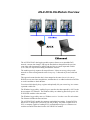
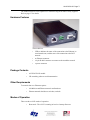
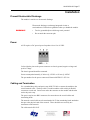
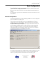
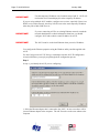
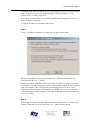
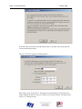
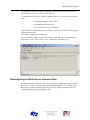
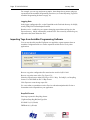
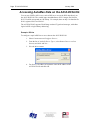
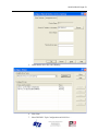
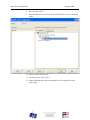
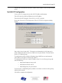
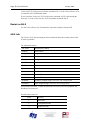
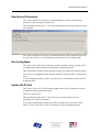
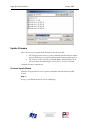
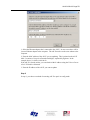
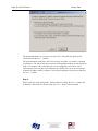
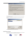
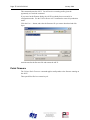
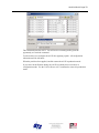
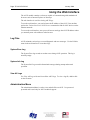
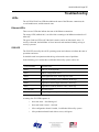
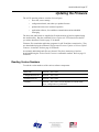
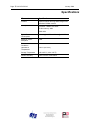
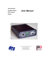
AN-X-DCSLOG
AutoMax DCSNet
Data Logging
Module
User Manual
Page 2 AN-X-DCSLOG
January 2008
Because of the variety of uses for the products described in this publication, those
responsible for the application and use of these products must satisfy themselves that all
necessary steps have been taken to assure that each application and use meets all
performance and safety requirements, including any applicable laws, regulations, codes
and standards. In no event will Quest Technical Solutions be responsible or liable for
indirect or consequential damage resulting from the use or application of these products.
Any illustrations, charts, sample programs, and layout examples shown in this publication
are intended solely for purposes of example. Since there are many variables and
requirements associated with any particular installation, Quest Technical Solutions does
not assume responsibility or liability (to include intellectual property liability) for actual
use based upon the examples shown in this publication.
Throughout this manual we use notes to make you aware of safety considerations.
Identifies information about practices or circumstances that can lead to
personal injury or death, property damage, or economic loss.
These warnings help to:
WARNING!
IMPORTANT!
TIP
•
identify a hazard
•
avoid the hazard
•
recognize the consequences
Identifies information that is especially important for successful
application and understanding of the product.
Identifies information that explains the best way to use the
AN-X-DCSLOG
Microsoft is a registered trademark of Microsoft Corporation.
Windows, Windows XP, Windows Vista and Windows 7 are trademarks of Microsoft Corporation.
ControlLogix, RSLinx and RSLogix 5000 are trademarks of the Allen-Bradley Company, Inc.
AN-X-DCSLOG MODULE OVERVIEW
2
Hardware Features
3
Package Contents
3
Other Requirements
3
Modes of Operation
3
INSTALLATION
5
Prevent Electrostatic Discharge
5
Power
5
Cabling and Termination
5
Ethernet Cabling
6
Software Installation
6
BASIC CONFIGURATION
7
Ethernet Configuration
7
Reconfiguring an AN-X from an Unknown State
11
LOGGING DATA
12
Logger Configuration File
12
Tag Definition File
13
Running the Log Service
14
Logged Data Files
14
The Application Log
15
Using AN-X-DCSLOG with InSQL
15
Importing Tags from AutoMax Programming Software
16
ACCESSING AUTOMAX DATA ON THE AN-X-DCSLOG
18
Page 4 AN-X-DCSLOG
January 2008
USING ANXINIT
22
AnxInit Log
22
Locating Available AN-X Modules
23
Selecting an AN-X
24
Set AN-X IP Configuration
25
Restart an AN-X
26
AN-X Info
26
Read Kernel Parameters
27
Run Config Mode
27
Update AN-X Flash
27
Update Firmware
Firmware Update Wizard
Update Firmware Command
28
28
31
Patch Firmware
32
USING THE WEB INTERFACE
34
Log Files
System Error Log
System Info Log
View All Logs
34
34
34
34
Administration Menu
34
TROUBLESHOOTING
35
LEDs
Ethernet LEDs
SYS LED
NET LED – Network Status
35
35
35
36
UPDATING THE FIRMWARE
37
Reading Version Numbers
37
SPECIFICATIONS
38
SUPPORT
39
WARRANTY
40
AN-X-DCSLOG Module Overview
The AN-X-DCSLOG data logging module captures frames on an AutoMax DCS
network, extracts data changes, and logs the data that has changed from the previous
scan, along with timestamps to millisecond precision, to comma separated variable
(CSV) files, for import into trending and database software.
The module passively captures all network frames. It does not occupy a drop on the
network or affect existing network traffic in any way. It discards any frames with bad
status.
This approach means that the data is time stamped at the same time as it is sent on
DCSNet, not at some later sampled time, and that there is no added overhead on DCSNet
or on the AutoMax to obtain the data.
You select which data (by drop, register and optionally bit) you want to log, in a comma
separated variable file.
The Windows logger utility, AnxDcsLog.exe, transfers the data captured by AN-X to the
host computer over Ethernet. The Windows utility can obtain log data from up to 4 ANX-DCSLOG modules at the same time
The Windows logger utility runs as a Windows service. It writes a new file each minute.
The filename includes the date and time.
The AN-X-DCSLOG module also supports unscheduled messaging. It maps DCSNet
data to PLC-5 integer files N100-N155, one file per drop. Any OPC or DDE server or
PLC or computer capable of sending PCCC unscheduled messages over Ethernet can
read the current DCSNet data from the AN-X-DCSLOG module.
AN-X-DCSLOG Page 3
The module firmware can be updated over Ethernet using the Windows utility supplied.
Refer to page 37 for details.
Hardware Features
The module has:
•
LEDs to indicate the status of the connection to the Ethernet, its
own internal state, and the state of the connection to the DCS
network
•
an Ethernet connector
•
a 9-pin D-shell connector to connect to the AutoMax network
•
a power connector
Package Contents
•
AN-X-DCSLOG module
•
CD containing software and documentation
Other Requirements
To transfer data over Ethernet requires:
•
100 Mbit/second Ethernet network and hardware
•
Ethernet network should uses switches, not hubs
Modes of Operation
There are three AN-X modes of operation:
•
Boot mode. The AN-X is running its low level startup firmware.
Page 4 AN-X-DCSLOG
January 2008
•
Configuration mode. This is the mode when you are updating the firmware
in the AN-X.
•
Production mode. This is the normal runtime mode of operation.
AN-X-DCSLOG Page 5
Installation
Prevent Electrostatic Discharge
The module is sensitive to electrostatic discharge.
Electrostatic discharge can damage integrated circuits or
semiconductors. Follow these guidelines when you handle the module:
WARNING!
•
Touch a grounded object to discharge static potential
•
Do not touch the connector pins
Power
AN-X requires a DC power input of anywhere from 12 to 24 VDC.
Left to right the pins on the power connector are chassis ground, negative voltage and
positive voltage.
The chassis ground should be connected.
Power consumption internally is 300 mA @ 12VDC or 150 mA @ 24VDC.
The part number for the power connector is Phoenix MSTB 2.5/3-ST-5.08
Cabling and Termination
Use a standard drop cable and passive tap (M/N 57C380) to connect the module to the
coaxial network cable. The drop cable is a multi-conductor cable with 9-pin D-shell
connectors at each end. Connect one end to the connector on the module and the other
end to the passive tap.
The passive tap has two BNC connectors for connection to the coaxial cables and
terminating loads.
The network coaxial cable must be terminated with 75 ohm terminating loads attached to
the taps at the physical ends of the network. There should be two and only two
terminators on the network.
The cable must be RG-59/U.
Page 6 AN-X-DCSLOG
January 2008
Ethernet Cabling
AN-X has a standard RJ-45 connector for connecting to Ethernet.
If you are connecting AN-X to an existing network through a router or switch, use a
standard Ethernet cable.
If you are connecting directly between a computer and AN-X, use a crossover cable.
Software Installation
You must uninstall any previous version of the software before you can install a new
version. Use the Windows Control Panel Add and Remove Programs to remove the old
version.
Insert the CD supplied with the AN-X module and run the program setup.exe on the CD.
AN-X-DCSLOG Page 7
Basic Configuration
The AN-X-DCSLOG module captures data from a Reliance AutoMax DCSnet network
and passes that data to a computer over Ethernet.
Before you can use the AN-X-DCSLOG, you must configure its network properties on
Ethernet.
No configuration is required on the AutoMax DCS network since the module is not active
on the network.
Ethernet Configuration
AN-X can be configured to use a static (unchanging) IP address or it can be configured to
obtain its IP address from a DHCP server.
Unless you have control of the DHCP server, in most applications you will want to
configure AN-X to use a static IP address. Otherwise the DHCP server may assign a
different IP address each time AN-X powers up, and any software that accesses the ANX module would have to be reconfigured.
AN-X is shipped with DHCP enabled. If it finds a DHCP server on the network, the
DHCP server assigns it an IP address. You can use the utility AnxInit to find the IP
address that the DHCP server has assigned. Select Utilities/Locate All AN-X Modules
and AnxInit will locate the AN-X and display its IP address.
If AN-X does not find a DHCP server within about three minutes of starting up, it reverts
to a temporary static IP address of 192.168.0.41 If AN-X is using this temporary IP
address, it repeatedly flashes the SYS LED three times followed by a pause.
Page 8 AN-X-DCSLOG
IMPORTANT!
January 2008
Use this temporary IP address only for initial setup of AN-X. AN-X will
not function for its intended purpose at the temporary IP address.
If you are using multiple AN-X modules, configure one at a time, especially if there is no
DHCP server on the network, since they will all revert to the same temporary IP address
when they fail to find a DHCP server.
IMPORTANT!
If you are connecting AN-X to an existing Ethernet network, consult the
network administrator to obtain information about how you should
configure AN-X and to obtain a static IP address for AN-X.
IMPORTANT!
The AN-X must be on the local Ethernet when you set its IP address.
You configure the Ethernet properties using the Windows utility AnxInit supplied with
AN-X.
Use the Configuration/AN-X IP Settings command to start the AN-X IP configuration
wizard, which takes you step by step through the IP configuration process.
Step 1
In step 1, you identify the AN-X you are configuring.
1. Select the Ethernet adapter that’s connected to the AN-X. In most cases there will be
just one Ethernet adapter in the computer. The AN-X must be on the same subnet as the
computer.
AN-X-DCSLOG Page 9
2. Enter the MAC address of the AN-X you are configuring. This is printed on the AN-X
label. It consists of six pairs of hexadecimal digits, separated by hyphens. In the
example above, it’s 00-0c-1a-00-00-09.
If the AN-X is already online, you can obtain its MAC address using the Utilities/Locate
All AN-X Modules command.
3. Enter the IP address you intend the AN-X to use.
Step 2
In step 2, you choose a method of restarting AN-X to put it in boot mode.
The preferred method is to cycle power on the AN-X. Select the first option on the
screen and click the Next >> button.
The second method, useful if the AN-X in not easily accessible, is to send it a command
over Ethernet. The AN-X must be powered on and completely running for this method to
work. For example, if this is the first time you are configuring a new AN-X, allow
sufficient time for it to acquire an IP address from a DHCP server or to time out and use
its default IP address (about 3 minutes). Select the second option on the screen and click
the Next >> button.
Step 3:
Wait for AN-X to enter boot mode. While AnxInit is waiting, the Next>> button will be
disabled. When AN-X is in boot mode, the Next>> button will be enabled.
Page 10 AN-X-DCSLOG
January 2008
If the AN-X does not enter boot mode within about 10 seconds, return to the previous
screens and check the entries.
The AN-X TCP/IP Configuration dialog appears.
Enter a Host Name for the AN-X. This name is used internally by AN-X and may be
used to identify the AN-X if you have a DNS server on your network. The name can be
from 1 to 31 characters long.
AN-X-DCSLOG Page 11
To configure the AN-X to obtain its IP address from a DHCP server on the network,
select Obtain an IP address automatically (DHCP)
To configure the AN-X to use a static IP address, select Use the following Settings and
enter:
•
the desired IP address for the AN-X.
•
the Subnet mask for the AN-X
•
the default gateway for your network.
You must enter a valid default gateway address even if there is no device at the gateway
address on the network.
Click OK to complete the configuration.
If you Cancel the Configuration/AN-X IP Settings command, AN-X is left running the
boot code. Use the Utilities/Restart AN-X command to restart the AN-X.
Reconfiguring an AN-X from an Unknown State
It sometimes happens that an AN-X has been previously configured with an IP address
that causes it to be inaccessible on the current Ethernet network. To reconfigure it to a
known state, run the command Configuration/AN-X IP Settings to start the AN-X IP
Configuration Wizard and reconfigure AN-X.
Page 12 AN-X-DCSLOG
January 2008
Logging Data
Use the following steps to log data using the AN-X-DCSLOG:
1. Create the configuration file.
2. Create the tag file.
3. Start the logger service.
4. Process the data files.
Logger Configuration File
When the AnxDcsLog.exe service starts, it reads a logger configuration file called
AnxDcsLogConf.csv to set its configuration. This file must be in the same directory as
the AnxDcsLog.exe executable file.
The logger configuration file contains a section for each AN-X-DCSLOG module from
which the logger is obtaining data. It can contain configuration information for up to 4
AN-X modules
Each section contains the following lines.
DeviceName
This is the name assigned to the AN-X being configured. It can be from 1 to 32
characters long.
The name is used to name the data files and to identify the source of messages in the
application log (see page 15).
ImportPath
The import path identifies the directory where the data files are to be written.
DeviceIP
The DeviceIP is the IP address of the AN-X module being configured.
RefreshMs
The AN-X-DCSLOG module captures network frames and logs all data changes on the
selected drops and registers.
The AN-X also logs all the selected data at a specified rate, even if it hasn’t changed.
You set the interval with the refresh rate, from 0 to 60000 ms. When the refresh timer
expires, the AN-X module starts logging all the selected data as it is received from
DCSNet, regardless of change.
If the refresh time is shorter than the DCS network scan time, the data is logged at the
DCS scan time, as it comes off the network.
AN-X-DCSLOG Page 13
TagFile
The tag file contains the name of the file that contains the data to be logged: the tag
names for the points and their addresses (drop, register and, for Boolean data, the bit).
The contents of the tag definition file are described below.
Example
The following configuration file configures two AN-X-DCSLOG modules, one at IP
address 192.168.0.9 and the other at IP address 192.168.0.10
DeviceName,AmxLog9
ImportPath,c:\InSQL\DATA\DataImport\Fastload
DeviceIp,192.168.0.9
RefreshMs,60000
TagFile,DcsLog1.csv
DeviceName,AmxLog10
ImportPath,c:\InSQL\DATA\DataImport\Fastload
DeviceIp,192.168.0.10
RefreshMs,60000
TagFile,DcsLog2.csv
If you change the configuration file, you must stop and restart the logger service, either
from the command line or from the Control Panel.
Tag Definition File
The tag definition file is a comma separated variable (CSV) file that defines the points to
be logged. Each line defines one point. Each line consists of:
•
tagname, up to 32 characters
•
drop number, 0 to 55
•
register, 0 to 63
•
bit, 0 to 15
•
type, WORD or BOOLEAN
Fields are separated by commas.
For drop 0, only registers 32-39 are valid.
The bit number is required only for BOOLEAN data and is ignored for WORD data.
You cannot create tags that have the same combination of drop and register. For
example, you cannot create a WORD tag for drop 1, register 32, and also create tags for
BOOLEAN tags using bits in drop 1, register 32.
Page 14 AN-X-DCSLOG
January 2008
Examples
DcsTest_00_32,00,32,,WORD
DcsTest_00_33_01,00,33,1,BOOLEAN
Running the Log Service
The executable program, AnxDcsLog.exe, supports the following command line options.
Option
Meaning
-i
install the executable as a Windows service
-u
uninstall
-r
run the service
-s
stop the service
-h
display the usage statement
You must install the service before it can run. To install the service, type:
anxdcslog -i
For example, to run the service, type
anxdcslog -r
When you install the logger service, it is set to run automatically. You can change it to
manual from the Control Panel. Select Start/Control Panel/Administrative
Tools/Services, locate the AnxDcsLog service in the list, right click on it and select
Properties from the menu. You can then change the Startup Type:
Logged Data Files
Logged data files have a name that is made up of the DeviceName of the AN-XDCSLOG module that captured the data and the date and time that the data was captured.
Times are expressed in Universal Time.
The files have a header that is meant for use with Wonderware InSQL. It contains the
following lines:
ASCII
,
wwAdmin,0,Server Local,10,1
AN-X-DCSLOG Page 15
The header is followed by data records. These consist of:
•
the tag name
•
0 (original value)
•
date
•
time
•
1 (raw data)
•
value
•
192 (quality detail)
Example
DcsTest_01_32,0,2004/08/04,20:00:49.875,1,15037,192
The Application Log
AnxDcsLog logs information and error messages to the file AxDcsLog.txt in the same
directory as AnxDcsLog.exe
Each time the service starts, it deletes any previous version of the application log file.
You can use the DeviceName to identify the AN-X associated with a message.
Example
2004/08/04,20:16:49
2004/08/04,20:16:49
2004/08/04,20:16:49
2004/08/04,20:16:49
2004/08/04,20:16:49
2004/08/04,20:16:49
2004/08/04,20:16:49
2004/08/04,20:17:46
2004/08/04,20:17:46
2004/08/04,20:17:46
2004/08/04,20:17:46
2004/08/04,20:17:46
:INFO - Starting AnxDcsLog service (v1.0.0.19) ...
:DEBUG - configured drop 0 - ff,0
:DEBUG - configured drop 1 - ffffffff,ffffffff
:DEBUG - configured drop 0 - ff,0
:DEBUG - configured drop 2 - ffffffff,ffffffff
:INFO - Starting the log function for AmxLog9
:INFO - Starting the log function for AmxLog10
:DEBUG - SERVICE_CONTROL_STOP
:INFO - stop capture for device AmxLog9
:DEBUG - Thread for AmxLog9 is dead
:INFO - stop capture for device AmxLog10
:DEBUG - Thread for AmxLog10 is dead
Using AN-X-DCSLOG with InSQL
Creating the Tag Database
Before InSQL can read the data logged by AnxDcsLog.exe, the corresponding tags must
exist in its tag database.
The easiest way to create the tags is to create a word and boolean tag in InSQL, export
those tags to a CSV file, edit the CSV file to create additional tags, then import the
modified file into InSQL.
Page 16 AN-X-DCSLOG
January 2008
For example, you can copy and paste tag entries, then change the tag names using tags
exported from the AutoMax Programming Executive (see section Importing Tags from
AutoMax Programming Software on page 16).
Logging Data
In the logger configuration file, set the ExportPath to the FastLoad directory for InSQL,
usually \InSQL\DATA\DataImport\Fastload
Run the service. AnxDcsLog.exe captures changing network data and logs it to the
Export directory. InSQL automatically reads the CSV files created by AnxDcsLog.exe,
imports the data, then deletes the files.
Importing Tags from AutoMax Programming Software
You can use the utility AnxDcsTagExport.exe supplied to export tagnames from an
AutoMax Configuration file to a comma separated variable file for use by other
applications.
Browse or type the configuration file name into the AmxDcsCnfFile field.
Browse or type the name of the Tag Export File.
Select the export format, either Drop/Reg or PLC-5 Map. For InSQL, use Drop/Reg
format. For OPC/HMI use PLC-5 Map format.
Click Export to create the tag export file.
Use a text editor or spreadsheet such as Excel to edit and manipulate this file into a
format that can be imported into your application.
Drop/Ref Format
Some tags exported in Drop/Reg format:
;TagName,Drop,Reg,Bit,DataType,Slot
GLOBAL32,0,32,,Word,4
FREDA010,1,0,,Word,4
AN-X-DCSLOG Page 17
FREDA011,1,1,,Word,4
FREDA012,1,2,,Word,4
PLC-5 Map
Some tags exported in PLC-5 Map format:
;TagName,Address,DataType,Slot
GLOBAL32,N100:32,Word,4
FREDA010,N101:0,Word,4
FREDA011,N101:1,Word,4
Page 18 AN-X-DCSLOG
January 2008
Accessing AutoMax Data on the AN-X-DCSLOG
You can use a DDE or OPC server, such as RSLinx, to access the DCS data directly on
the AN-X-DCSLOG. The module maps AutoMax data to PLC-5 integer files N100 to
N155. Each file corresponds to a DCS drop. For example, data on drop 2 in found in file
N102, registers N102:0 to N102:63.
The AN-X-DCSLOG supports Word Range read and Typed read messages, with either
logical ASCII or logical binary addressing.
Example: RSLinx
To configure a topic in RSLinx to access data on the AN-X-DCSLOG:
1. Select Communications/Configure Drivers…
2. From the list of Available Driver Types:, select Remote Devices via Linx
Gateway and click Add New…
3. Give the driver a name
4. For Server’s IP Address or hostname: enter the IP address of the
AN-X-DCSLOG and click OK.
AN-X-DCSLOG Page 19
5. Check that the driver has status Running
6. Click Close
7. Select DDE/OPC Topic Configuration and click New…
Page 20 AN-X-DCSLOG
January 2008
8. Give the topic a name.
9. Select the Data Source tab, click on the AN-X module to select it, and click
Apply.
10. Select the Data Collection tab.
11. Set the Processor Type to PLC-5
12. Check Polled Messages and set the update time to an appropriate value.
Click Apply.
AN-X-DCSLOG Page 21
13. Click Done.
You should now be able to access data using any DDE or OPC client capable of
communicating with RSLinx.
Details for configuring other OPC servers are found in technical notes on the QTS
website, www.qtsusa.com
Page 22 AN-X-DCSLOG
January 2008
Using AnxInit
AnxInit is a 32-bit Windows application supplied with AN-X to perform the following
functions:
•
Locate and identify AN-X modules on the Ethernet network
•
Select a specific AN-X for configuration
•
Set the IP address and other network parameters for an AN-X
•
Restart an AN-X
•
Display information about the selected AN-X
•
Read the kernel parameters for the selected AN-X
•
Update the flash (low level firmware) on the selected AN-X
•
Update the firmware on the selected AN-X
•
Patch the firmware on the selected AN-X
In addition, it can be used to:
•
clear the AnxInit log
•
copy the contents of the log to the clipboard for use by another application.
This is often useful for technical support
AnxInit Log
AnxInit logs messages in its main window. These messages are often useful for
determining the cause of errors or for technical support.
To clear the log, select Edit/ClearLog.
To copy the contents of the Log to the Windows clipboard so that they can be pasted into
another application, select Edit/Copy.
AN-X-DCSLOG Page 23
AN-X Log
Locating Available AN-X Modules
To locate all accessible AN-X modules on the Ethernet network, select Utilities/Locate
All AN-X Modules.
AnxInit displays a list of the AN-X modules it finds, showing their MAC IDs, IP
addresses and host names.
This command is useful for determining IP addresses when they have been set by a
DHCP server or for confirming that an AN-X is accessible.
Page 24 AN-X-DCSLOG
January 2008
Selecting an AN-X
Before you can perform an operation on an AN-X, you must select it. Choose
Utilities/Select An AN-X to select a specific AN-X.
From the Adapter list, select the network adapter that connects to the Ethernet network
that contains the AN-X.
In the Ethernet MAC Address field, enter the MAC Address of the AN-X you wish to
select. It can be found on the AN-X label or using the Locate All AN-X Modules
command. The format is as shown above, six pairs of hexadecimal digits separated by
hyphens.
In the IP Address field, enter the Ethernet IP address of the AN-X you wish to select. It
can be found using the Locate All AN-X Modules command. The format is as shown
above, four decimal numbers each in the range 0 to 255.
Both MAC address and IP address must match the settings on the AN-X in order for
communication to occur.
Click OK to select the AN-X.
AN-X-DCSLOG Page 25
The title bar of AnxInit shows the MAC Address and IP Address of the currently selected
AN-X.
Set AN-X IP Configuration
Utilities/AN-X IP Configuration sets the AN-X IP address and hostname.
The AN-X must be on the local Ethernet to set its IP address.
First select the AN-X using the Utilities/Select An AN-X command.
Next select Utilities/AN-X IP Configuration. The AN-X TCP/IP Configuration dialog
appears.
Enter a Host Name for the AN-X. This name is used internally by AN-X and may be
used to identify the AN-X if you have a DNS server on your network. The name can be
from 1 to 31 characters long.
To configure the AN-X to obtain its IP address from a DHCP server on the network,
select Obtain an IP address automatically (DHCP)
To configure the AN-X to use a static IP address, select Use the following Settings and
enter the following:
•
the desired IP address for the AN-X.
•
the Subnet mask for the AN-X
•
the default gateway for your network.
You must enter a valid default gateway address even if there is no device at the gateway
address on the network.
Click OK to complete the configuration.
Page 26 AN-X-DCSLOG
January 2008
Utilities/AN-X IP Configuration resets the selected AN-X. Use the Utilities/Restart AN-X
to restart the AN-X in production mode.
If you Cancel the Utilities/AN-X IP Configuration command, AN-X is left running the
boot code. Use the Utilities/Restart AN-X command to restart the AN-X.
Restart an AN-X
Use the Utilities/Restart AN-X command to restart the currently selected AN-X.
AN-X Info
The Utilities/AN-X Info command provides information about the currently selected ANX in the log window.
The information shown:
AN-X Info
Ethernet MAC address
SerNum
Serial number
DaughterID
Daughterboard ID, 3 for AN-X-DCSLOG
BootRev
Boot code version
ConfigRev
Configuration kernel version
ProdRev
Production kernel version
HwRev
Hardware version
FirmwRev
Firmware release version (depends on current operating mode)
Status
see below
VendorId
Vendor ID
ProdId
Product ID
IpAddrStr
IP address assigned using Utilities/AN-X IP Configuration
HostName
Name assigned using Utilities/AN-X IP Configuration
In boot mode, FirmwRev, Vendor ID and Product ID and not valid, and IpAddrStr and
HostName are not shown.
Possible status values are:
Value
Meaning
1
Boot mode
2
Configuration mode
4
Production mode
AN-X-DCSLOG Page 27
Read Kernel Parameters
The Utilities/Read Kernel Parameters command displays various communications
parameters for the currently selected AN-X
This command resets the AN-X. You will be warned and given the opportunity to cancel
the command.
The Utilities/Read Kernel Parameters command leaves the AN-X running the boot code.
Use the Utilities/Restart AN-X command to restart the AN-X in production mode.
Run Config Mode
The Utilities/Run Config Mode command is used to restart the currently selected AN-X
in configuration mode (normally used internally for updating firmware).
This command is not used in normal operation but may be required for technical support.
The AN-X is in configuration mode when the SYS LED flashes red twice, followed by a
pause.
To exit configuration mode, use the Utilities/Restart AN-X command to restart AN-X in
production mode.
Update AN-X Flash
The Utilities/Update AN-X Flash command updates the low-level firmware (boot code,
configuration kernel, production kernel).
Files have extension qtf.
This command resets the AN-X. You will receive a warning and be given the
opportunity to Cancel the command.
If you cancel at the filename dialog, the AN-X has already been reset and is in boot
mode. Use the Utilities/Restart AN-X command to restart it in production mode.
Page 28 AN-X-DCSLOG
January 2008
Update Firmware
There are two ways to update all the firmware in an AN-X module.
1. The Configuration/Firmware Update command starts the firmware update
wizard, which takes you step by step through the firmware update process.
2. The Utilities/Update Firmware command updates all the firmware on an
AN-X you have selected using the Utilities/Select An AN-X command.
Firmware files have extension bin.
Firmware Update Wizard
Select the Configuration/Firmware Update command to start the firmware update
wizard.
Step 1:
In step 1, you identify the AN-X you are configuring.
AN-X-DCSLOG Page 29
1. Select the Ethernet adapter that’s connected to the AN-X. In most cases there will be
just one Ethernet adapter in the computer. The AN-X must be on the same subnet as the
computer.
2. Enter the MAC address of the AN-X you are updating. This is printed on the AN-X
label. It consists of six pairs of hexadecimal digits, separated by hyphens. In the
example above, it’s 00-0c-1a-00-00-09.
If the AN-X is already online, you can obtain its MAC address using the Utilities/Locate
All AN-X Modules command.
3. Enter the IP address of the AN-X you want to update
Step 2
In step 2, you choose a method of restarting AN-X to put it in config mode.
Page 30 AN-X-DCSLOG
January 2008
The preferred method is to cycle power on the AN-X. Select the first option on the
screen and click the Next >> button.
The second method, useful if the AN-X in not easily accessible, is to send it a command
over Ethernet. The AN-X must be powered on and completely running for this method to
work. For example, if this is the first time you are configuring a new AN-X, allow
sufficient time for it to acquire an IP address from a DHCP server or to time out and use
its default IP address (about 3 minutes). Select the second option on the screen and click
the Next >> button.
Step 3:
Wait for AN-X to enter config mode. While AnxInit is waiting, the Next>> button will
be disabled. When AN-X is in boot mode, the Next>> button will be enabled.
AN-X-DCSLOG Page 31
If the AN-X does not enter config mode within about 60 seconds, return to the previous
screens and check the entries.
Click the Next>> button, and select the firmware file you want to download and click
Open.
AnxInit transfers the firmware file and restarts the AN-X.
Update Firmware Command
The Utilities/Update Firmware command updates all the firmware on an AN-X you have
previously selected using the Utilities/Select An AN-X command.
Page 32 AN-X-DCSLOG
January 2008
This command resets the AN-X. You will receive a warning and be given the
opportunity to Cancel the command.
If you cancel at the filename dialog, the AN-X has already been reset and is in
configuration mode. Use the Utilities/Restart AN-X command to restart it in production
mode.
Click the Next>> button, and select the firmware file you want to download and click
Open.
AnxInit transfers the firmware file and restarts the AN-X.
Patch Firmware
The Utilities/Patch Firmware command applies small patches to the firmware running on
the AN-X.
These patch files files have extension pch.
AN-X-DCSLOG Page 33
This command resets the AN-X. You will receive a warning and be given the
opportunity to Cancel the command.
You do not have to reconfigure the AN-X after applying a patch. All configuration
information will be left intact.
When the patch has been applied, AnxInit restarts the AN-X in production mode.
If you cancel at the filename dialog, the AN-X has already been reset and is in
configuration mode. Use the Utilities/Restart AN-X command to restart it in production
mode.
Page 34 AN-X-DCSLOG
January 2008
Using the Web Interface
The AN-X module contains a webserver capable of communicating with standard web
browsers such as Internet Explorer or Netscape.
The web interface is used for viewing AN-X logs.
To use the web interface, you need to know the IP address of the AN-X. Run AnxInit
and use the Utilities/Locate All AN-X Devices command to find all AN-X devices on the
Ethernet network.
To access the web interface, start your web browser and type the AN-X IP address where
you normally enter web addresses in the browser.
Log Files
AN-X maintains various logs to record diagnostic and error messages. Use the Utilities
menu in the web interface to view these logs.
System Error Log
The System Error log records errors that occur during AN-X operation. This log is
normally empty.
System Info Log
The System Info Log records informational messages during startup and normal
operation.
View All Logs
Use View All Logs to list and view all the AN-X logs. To view a log file, double click
on the file name.
Administration Menu
The Administration Menu is used to view and edit files on AN-X. It is password
protected and is used only for AN-X technical support.
AN-X-DCSLOG Page 35
Troubleshooting
LEDs
The AN-X-DCSLOG has LEDs that indicate the state of the Ethernet connection, the
overall module state, and the network state
Ethernet LEDs
There are two LEDs that indicate the state of the Ethernet connection.
The orange LED, labelled 100, is on if the link is running at 100 Mbits/second and is off
otherwise.
The green Link/Act LED is off if the link is inactive and is on if the link is active. If
activity is detected, the link blinks at 30 ms intervals and continues blinking as long as
activity is present.
SYS LED
The SYS LED is used by the AN-X operating system and software to indicate the state of
operations and errors.
It should be used in conjunction with the logs to locate the cause of problems.
In the following, red 3 means three red flashes followed by a pause, and so on.
SYS LED State
Possible cause
Red 2
AN-X is in config mode
Red 3
DHCP configuration failed
Red 4
Fatal application error, check logs for cause
Red 5
Application memory access violation, check logs
Red 6
Application failed, illegal instruction, check logs
Red 7
Application crashed, unknown cause, check logs
Fast red flash
Reconfiguration
Slow red flash
script or application problem during startup
At startup, the SYS LED sequence is:
•
boot code starts – fast flashing red
•
boot code loads a kernel – solid red
•
if the configuration kernel is loaded, 2 red flashes followed by a pause
•
if the production kernel loads with no errors, solid green
Page 36 AN-X-DCSLOG
January 2008
NET LED – Network Status
The NET LED indicates the status of the AutoMax network.
Colour
Meaning
Green
Receiving frames with good status
Yellow
Not receiving any frames
Red
Have received a frame with bad status. Stays on for about 1 second
AN-X-DCSLOG Page 37
Updating the Firmware
The AN-X operating software consists of several parts:
•
boot code, runs at startup
•
configuration kernel, runs when you update firmware
•
production kernel, runs in normal operation
•
application software, for AutoMax communication and unscheduled
messaging
The boot code and kernels are supplied in file with extension qtf and are updated using
the AnxInit utility. Run the command Utilities/Update AN-X Flash and select the file
you wish to download. Refer to page 27 for details.
Firmware files contain the application programs for AN-X and have extension bin. They
are downloaded using the command Configuration/Firmware Update or Utilities/Update
Firmware in AnxInit. Refer to page 28 for details.
Occasionally individual patch files are released. They have extension pch and are
downloaded using the Utilities/Patch Firmware command in AnxInit. Refer to page 32
for details.
Reading Version Numbers
To read the version numbers of the various software components:
Boot code
AnxInit – AN-X Info
Configuration kernel
AnxInit – AN-X Info
Production kernel
AnxInit – AN-X Info
Firmware
AnxInit – AN-X Info (version depends on current mode,
boot, configuration or production)
Page 38 AN-X-DCSLOG
January 2008
Specifications
*Parameter
Specification
Function
Captures frames and logs data changes from
AutoMax DCSNet network
Description
Processor: 100MHz IDT MIPS
FLASH memory: 64M
RAM: 64M
Typical Power
Consumption
300 mA @ 12 VDC or 150 mA @ 24 VDC
Maximum Power
dissipation
3.6W
Environmental
Conditions:
Operational
Temperature
0-50°C (32-122°F)
Storage Temperature
–40 to 85°C (–40 to 185°F)
Relative Humidity
5-95% without condensation
AN-X-DCSLOG Page 39
Support
How to Contact Us: Sales and Support
Sales and Technical Support for this product are provided by ProSoft Technology.
Contact our worldwide Sales or Technical Support teams directly by phone or email:
Asia Pacific
+603.7724.2080, [email protected]
Europe – Middle East – Africa
+33 (0) 5.34.36.87.20, [email protected]
North America
+1.661.716.5100, [email protected]
Latin America (Sales only)
+1.281.298.9109, [email protected].
Page 40 AN-X-DCSLOG
January 2008
Warranty
Quest Technical Solutions warrants its products to be free from defects in workmanship
or material under normal use and service for three years after date of shipment. Quest
Technical Solutions will repair or replace without charge any equipment found to be
defective during the warranty period. Final determination of the nature and responsibility
for defective or damaged equipment will be made by Quest Technical Solutions
personnel.
All warranties hereunder are contingent upon proper use in the application for which the
product was intended and do not cover products which have been modified or repaired
without Quest Technical Solutions approval or which have been subjected to accident,
improper maintenance, installation or application, or on which original identification
marks have been removed or altered. This Limited Warranty also will not apply to
interconnecting cables or wires, consumables nor to any damage resulting from battery
leakage.
In all cases Quest Technical Solutions’ responsibility and liability under this warranty
shall be limited to the cost of the equipment. The purchaser must obtain shipping
instructions for the prepaid return of any item under this Warranty provision and
compliance with such instruction shall be a condition of this warranty.
Except for the express warranty stated above Quest Technical Solutions disclaims all
warranties with regard to the products sold hereunder including all implied warranties of
merchantability and fitness and the express warranties stated herein are in lieu of all
obligations or liabilities on the part of Quest Technical Solutions for damages including,
but not limited to, consequential damages arising out of/or in connection with the use or
performance of the Product.