1
SPAN™ Technology for OEMV
USER MANUAL
OM-20000104 Rev 7
Proprietary Notice
SPAN Technology for OEMV User Manual
Publication Number:
Revision Level:
Revision Date:
OM-20000104
7
2009/09/03
This manual reflects SPAN for OEMV firmware version SPAN3.620.
Proprietary Notice
Information in this document is subject to change without notice and does not represent a commitment
on the part of NovAtel Inc. The software described in this document is furnished under a licence
agreement or non-disclosure agreement. The software may be used or copied only in accordance with
the terms of the agreement. It is against the law to copy the software on any medium except as
specifically allowed in the license or non-disclosure agreement.
No part of this manual may be reproduced or transmitted in any form or by any means, electronic or
mechanical, including photocopying and recording, for any purpose without the express written
permission of a duly authorized representative of NovAtel Inc.
The information contained within this manual is believed to be true and correct at the time of
publication.
NovAtel, OEMV, CDU, ProPak, RT-20 and RT-2 are registered trademarks of NovAtel Inc.
SPAN, DL-V3, ProPak-V3, and PAC are trademarks of NovAtel Inc.
All other product or brand names are trademarks of their respective holders.
Manufactured and protected under U.S. Patent:
Narrow Correlator
#5,101,416
#5,390,207
#5,495,499
#5,809,064
PAC Correlator
#6,243,409 B1
#5,414,729
Dual Frequency GPS
#5,736,961
Anti-Jamming Technology
#5,734,674
Position for Velocity Kalman Filter
#6,664,923 B1
#7,193,559 B2
SPAN Technology
#6,721,657 B2
#6,750,816 B1
#7,346,452
10/932,497 (pending)
© Copyright 2006-2009 Novatel Inc. All rights reserved. Unpublished rights
reserved under International copyright laws. Printed in Canada on recycled paper.
Recyclable.
2
SPAN Technology for OEMV User Manual Rev 7
Table of Contents
Proprietary Notice
Software License
Terms and Conditions
Warranty Policy
Customer Service
Notices
Foreword
1 Introduction
2
8
10
13
15
16
17
19
1.1 Fundamentals of GPS/INS .............................................................................................20
1.2 Models and Features ......................................................................................................21
2 SPAN Installation
23
2.1 Hardware Description .....................................................................................................23
2.1.1 SPAN System Receivers......................................................................................24
2.1.2 Cables and Ports ..................................................................................................24
2.2 Hardware Set-Up ............................................................................................................25
2.2.1 Mount Antenna .....................................................................................................25
2.2.2 Mount IMU ............................................................................................................25
2.2.3 Connect COM Cables...........................................................................................26
2.2.4 Connect Power .....................................................................................................27
2.3 Software Configuration ...................................................................................................28
2.3.1 GPS Configuration................................................................................................28
2.3.2 SPAN IMU Configuration......................................................................................28
2.3.3 Configuration Command Summary ......................................................................32
3 SPAN Operation
33
3.1 Definition of Reference Frames Within SPAN ................................................................33
3.1.1 The Local-Level Frame (ENU)..............................................................................33
3.1.2 The SPAN Body Frame ........................................................................................34
3.1.3 The Enclosure Frame ...........................................................................................34
3.1.4 The Vehicle Frame ...............................................................................................34
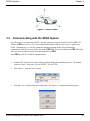
3.2 Communicating with the SPAN System..........................................................................35
3.2.1 INS Window in CDU .............................................................................................37
3.3 Real-Time Operation ......................................................................................................37
3.3.1 System Start-Up and Alignment Techniques........................................................39
3.3.2 Navigation Mode...................................................................................................40
3.3.3 Data Collection .....................................................................................................41
3.3.4 Lever Arm Calibration Routine .............................................................................42
3.3.5 Vehicle to SPAN frame Angular Offsets Calibration Routine ...............................43
3.3.6 SPAN Wheel Sensor Messages...........................................................................44
3.4 Data Collection for Post Processing ...............................................................................45
A Technical Specifications
47
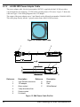
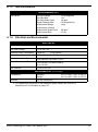
A.1 LN-200 IMU ....................................................................................................................47
A.1.1 LN-200 IMU Interface Cable ................................................................................49
A.1.2 LN-200 IMU Power Adapter Cable.......................................................................50
SPAN Technology for OEMV User Manual Rev 7
3
A.1.3 IMU Performance .................................................................................................51
A.1.4 Electrical and Environmental................................................................................51
A.2 iIMU-FSAS......................................................................................................................52
A.2.1 iIMU-FSAS Interface Cable ..................................................................................55
A.2.2 iIMU-FSAS Odometer Cabling .............................................................................56
A.2.3 IMU Performance .................................................................................................59
A.2.4 Electrical and Environmental................................................................................59
A.3 HG1700 IMU...................................................................................................................60
A.3.1 HG1700 IMU Interface Cable ...............................................................................62
A.3.2 IMU Performance .................................................................................................62
A.3.3 Electrical and Environmental................................................................................63
B INS Commands
64
B.1 Using a Command as a Log ...........................................................................................64
B.2 INS-Specific Commands ................................................................................................64
B.2.1 APPLYVEHICLEBODYROTATION Enable Vehicle to Body Rotation .................65
B.2.2 FRESET Factory Reset .....................................................................................66
B.2.3 INSCOMMAND INS Control Command.............................................................67
B.2.4 INSPHASEUPDATE INS Phase Update Control...............................................68
B.2.5 INTERFACEMODE Set Interface Type for a Port .............................................69
B.2.6 INSZUPT Request Zero Velocity Update ..........................................................72
B.2.7 LEVERARMCALIBRATE INS Calibration Command ........................................73
B.2.8 NMEATALKER Set the NMEA talker ID V123 ................................................75
B.2.9 RVBCALIBRATE Vehicle to Body Rotation Control ..........................................76
B.2.10 SETIMUORIENTATION Set IMU Orientation ..................................................77
B.2.11 SETIMUTOANTOFFSET Set IMU to Antenna Offset......................................80
B.2.12 SETIMUTYPE Set IMU Type...........................................................................81
B.2.13 SETINITATTITUDE Set Initial Attitude of SPAN in Degrees ...........................83
B.2.14 SETINITAZIMUTH Set Initial Azimuth and Standard Deviation.......................85
B.2.15 SETINSOFFSET Set INS Offset......................................................................87
B.2.16 SETMARK1OFFSET Set Mark1 Offset ...........................................................88
B.2.17 SETMARK2OFFSET Set Mark2 Offset ...........................................................89
B.2.18 SETWHEELPARAMETERS Set Wheel Parameters .......................................90
B.2.19 VEHICLEBODYROTATION Vehicle to SPAN frame Rotation ........................91
B.2.20 WHEELVELOCITY Wheel Velocity for INS Augmentation ..............................93
C INS Logs
94
C.1 Description of ASCII and Binary Logs with Short Headers ............................................95
C.2 INS-Specific Logs...........................................................................................................96
C.2.1 BESTGPSPOS Best GPS Position ...................................................................97
C.2.2 BESTGPSVEL Best Available GPS Velocity Data ............................................102
C.2.3 BESTLEVERARM IMU to Antenna Lever Arm..................................................104
C.2.4 INSATT INS Attitude..........................................................................................105
C.2.5 INSATTS Short INS Attitude..............................................................................106
C.2.6 INSCOV INS Covariance Matrices ....................................................................107
C.2.7 INSCOVS Short INS Covariance Log................................................................109
C.2.8 INSPOS INS Position ........................................................................................110
C.2.9 INSPOSS Short INS Position ............................................................................111
C.2.10 INSPOSSYNC Time Synchronised INS Position ............................................112
C.2.11 INSPVA INS Position, Velocity and Attitude....................................................113
C.2.12 INSPVAS Short INS Position, Velocity and Attitude........................................114
C.2.13 INSSPD INS Speed.........................................................................................115
C.2.14 INSSPDS Short INS Speed.............................................................................116
4
SPAN Technology for OEMV User Manual Rev 7
C.2.15 INSUPDATE INS Update ................................................................................117
C.2.16 INSVEL INS Velocity .......................................................................................118
C.2.17 INSVELS Short INS Velocity ...........................................................................119
C.2.18 MARK1PVA Position, Velocity and Attitude at Mark1 .....................................120
C.2.19 MARK2PVA Position, Velocity and Attitude at Mark2 .....................................121
C.2.20 PASHR NMEA, Inertial Attitude Data ..............................................................122
C.2.21 RAWIMU Raw IMU Data .................................................................................123
C.2.22 RAWIMUS Short Raw IMU Data .....................................................................127
C.2.23 TIMEDWHEELDATA Timed Wheel Data ........................................................129
C.2.24 VEHICLEBODYROTATION Vehicle to SPAN frame Rotation..........................130
C.2.25 WHEELSIZE Wheel Size ................................................................................131
D Command Prompt Interface
132
D.1 DOS ...............................................................................................................................133
D.2 Windows.........................................................................................................................134
E HG1700 IMU Installation
135
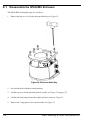
E.1 Disassemble the SPAN IMU Enclosure .........................................................................136
E.2 Install the HG1700 Sensor Unit......................................................................................137
E.3 Make the Electrical Connections ....................................................................................138
E.4 Re-Assemble the SPAN IMU Enclosure ........................................................................139
F LN-200 IMU Installation
140
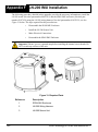
F.1 Disassemble the SPAN IMU Enclosure..........................................................................141
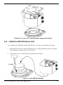
F.2 Install the LN-200 Sensor Unit........................................................................................142
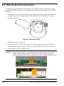
F.3 Make the Electrical Connections ....................................................................................143
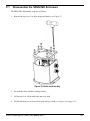
F.4 Re-Assemble the SPAN IMU Enclosure.........................................................................144
G Frequently Asked Questions
H Replacement Parts
145
147
H.1 SPAN System ................................................................................................................147
H.2 Accessories and Options ...............................................................................................147
H.3 Manufacturer’s Part Numbers ........................................................................................147
SPAN Technology for OEMV User Manual Rev 7
5
Figures
1
2
3
4
5
6
7
8
9
10
11
12
13
14
15
16
17
18
19
20
21
22
23
24
25
26
27
28
29
30
31
32
33
34
35
36
37
6
SPAN System Receiver ................................................................................................19
SPAN System IMUs ......................................................................................................19
Basic Set-Up .................................................................................................................23
Receiver Enclosure Back Panel ...................................................................................24
Local-Level Frame (ENU) .............................................................................................33
The Enclosure Frame ...................................................................................................34
Vehicle Frame ..............................................................................................................35
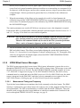
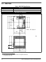
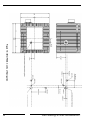
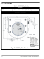
LN-200 IMU Enclosure Top/Bottom Dimensions and Centre of Navigation .................47
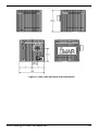
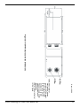
LN-200 Enclosure Side Dimensions .............................................................................48
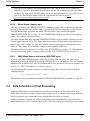
LN-200 Interface Cable ................................................................................................49
IMU Interface Cable Pin-Out (ProPak-V3) ....................................................................49
LN-200 Power Cable ....................................................................................................50
IMU Power Cable Pin-Out ............................................................................................50
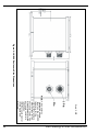
iIMU-FSAS Top/Bottom Dimensions ............................................................................52
iIMU-FSAS Enclosure Side Dimensions .......................................................................53
iIMU-FSAS Centre of Navigation ..................................................................................54
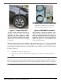
Corrsys Datron WPT .....................................................................................................57
iMAR iMWS Pre-Installed .............................................................................................57
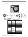
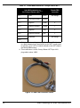
iIMU-FSAS Interface Cable ..........................................................................................58
HG1700 Top/Bottom Dimensions .................................................................................60
HG1700 Enclosure Side Dimensions ...........................................................................61
Frame of Reference ......................................................................................................77
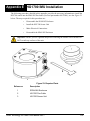
Required Parts ..............................................................................................................135
Bolts and Allan Key ......................................................................................................136
Lift Top Cover, Tube Body and 3 Ring Spacer Screws ................................................137
SPAN IMU Re-Assembly ..............................................................................................137
Attach Flex Cable .........................................................................................................138
Incorrect (Bowed) Flex Cable Installation .....................................................................138
Correct (Flat) Flex Cable Installation ............................................................................138
HG1700 SPAN IMU ......................................................................................................139
Required Parts ..............................................................................................................140
Bolts and Allan Key ......................................................................................................141
Lift Top Cover and Tube Body ......................................................................................142
SPAN IMU Re-Assembly ..............................................................................................142
Attach Wiring Harness ..................................................................................................143
Attach Samtec Connector .............................................................................................143
LN-200 SPAN IMU .......................................................................................................144
SPAN Technology for OEMV User Manual Rev 7
Tables
1
2
3
4
5
6
7
8
9
10
11
12
13
14
15
16
17
18
19
20
21
22
23
24
25
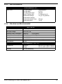
SPAN-Compatible Receiver and IMU Models ...............................................................21
Receiver Enclosure Back Panel Labels.........................................................................24
IMU Power Supply .........................................................................................................27
Enable INS Commands .................................................................................................28
Inertial Solution Status...................................................................................................38
Solution Parameters ......................................................................................................41
LN-200 IMU Specifications ............................................................................................47
iIMU-FSAS Specifications..............................................................................................52
IMU Interface Cable Pin-Out..........................................................................................55
Cable Modification for Corrsys Datron WPT..................................................................58
HG1700 IMU Specifications...........................................................................................60
FRESET Target .............................................................................................................66
Serial Port Interface Modes ...........................................................................................70
COM Serial Port Identifiers ............................................................................................71
NMEA Talkers ...............................................................................................................75
Full Mapping Definitions ................................................................................................79
IMU Type .......................................................................................................................82
Short ASCII Message Header Structure........................................................................95
Short Binary Message Header Structure .......................................................................95
Position or Velocity Type ...............................................................................................99
Solution Status ..............................................................................................................101
Wheel Status .................................................................................................................117
iIMU-FSAS Status .........................................................................................................124
HG1700 and LN200 Status ...........................................................................................125
Raw IMU Scale Factors .................................................................................................128
SPAN Technology for OEMV User Manual Rev 7
7
Software License
Software License
BY INSTALLING, COPYING, OR OTHERWISE USING THE SOFTWARE PRODUCT, YOU AGREE
TO BE BOUND BY THE TERMS OF THIS AGREEMENT. IF YOU DO NOT AGREE WITH THESE
TERMS OF USE, DO NOT INSTALL, COPY OR USE THIS ELECTRONIC PRODUCT (SOFTWARE,
FIRMWARE, SCRIPT FILES, OR OTHER ELECTRONIC PRODUCT WHETHER EMBEDDED IN THE
HARDWARE, ON A CD OR AVAILABLE ON THE COMPANY WEB SITE) (hereinafter referred to as
"Software").
1. License: NovAtel Inc. ("NovAtel") grants you a non-exclusive, non-transferable license (not a sale)
to, where the Software will be used on NovAtel supplied hardware or in conjunction with other NovAtel
supplied software, use the Software with the product(s) as supplied by NovAtel. You agree not to use
the Software for any purpose other than the due exercise of the rights and licences hereby agreed to
be granted to you.
2. Copyright: NovAtel owns, or has the right to sublicense, all copyright, trade secret, patent and other
proprietary rights in the Software and the Software is protected by national copyright laws, international
treaty provisions and all other applicable national laws. You must treat the Software like any other copyrighted material except that you may make one copy of the Software solely for backup or archival purposes (one copy may be made for each piece of NovAtel hardware on which it is installed or where
used in conjunction with other NovAtel supplied software), the media of said copy shall bear labels
showing all trademark and copyright notices that appear on the original copy. You may not copy the
product manual or written materials accompanying the Software. No right is conveyed by this Agreement for the use, directly, indirectly, by implication or otherwise by Licensee of the name of NovAtel, or
of any trade names or nomenclature used by NovAtel, or any other words or combinations of words
proprietary to NovAtel, in connection with this Agreement, without the prior written consent of NovAtel.
3. Patent Infringement: NovAtel shall not be liable to indemnify the Licensee against any loss sustained by it as the result of any claim made or action brought by any third party for infringement of any
letters patent, registered design or like instrument of privilege by reason of the use or application of the
Software by the Licensee or any other information supplied or to be supplied to the Licensee pursuant
to the terms of this Agreement. NovAtel shall not be bound to take legal proceedings against any third
party in respect of any infringement of letters patent, registered design or like instrument of privilege
which may now or at any future time be owned by it. However, should NovAtel elect to take such legal
proceedings, at NovAtel's request, Licensee shall co-operate reasonably with NovAtel in all legal
actions concerning this license of the Software under this Agreement taken against any third party by
NovAtel to protect its rights in the Software. NovAtel shall bear all reasonable costs and expenses
incurred by Licensee in the course of co-operating with NovAtel in such legal action.
4. Restrictions: You may not:
(a)
copy (other than as provided for in paragraph 2), distribute, transfer, rent, lease, lend, sell or
sublicense all or any portion of the Software except in the case of sale of the hardware to a
third party;
(b)
modify or prepare derivative works of the Software;
(c)
use the Software in connection with computer-based services business or publicly display
visual output of the Software;
(d)
transmit the Software over a network, by telephone or electronically using any means (except
when downloading a purchased up[grade from the NovAtel web site); or
(e)
reverse engineer, decompile or disassemble the Software.
You agree to keep confidential and use your best efforts to prevent and protect the contents of the Software from unauthorized disclosure or use.
8
SPAN Technology for OEMV User Manual Rev 7
Software License
5. Term and Termination: This Agreement and the rights and licences hereby granted shall continue
in force in perpetuity unless terminated by NovAtel or Licensee in accordance herewith. In the event
that the Licensee shall at any time during the term of this Agreement: i) be in breach of its obligations
hereunder where such breach is irremediable or if capable of remedy is not remedied within 30 days of
notice from NovAtel requiring its remedy; then and in any event NovAtel may forthwith by notice in writing terminate this Agreement together with the rights and licences hereby granted by NovAtel.
Licensee may terminate this Agreement by providing written notice to NovAtel. Upon termination, for
any reasons, the Licensee shall promptly, on NovAtel's request, return to NovAtel or at the election of
NovAtel destroy all copies of any documents and extracts comprising or containing the Software. The
Licensee shall also erase any copies of the Software residing on Licensee's computer equipment. Termination shall be without prejudice to the accrued rights of either party, including payments due to
NovAtel. This provision shall survive termination of this Agreement howsoever arising.
6. Warranty: NovAtel does not warrant the contents of the Software or that it will be error free. The
Software is furnished "AS IS" and without warranty as to the performance or results you may obtain by
using the Software. The entire risk as to the results and performance of the Software is assumed by
you. See product enclosure, if any for any additional warranty.
7. Indemnification: NovAtel shall be under no obligation or liability of any kind (in contract, tort or otherwise and whether directly or indirectly or by way of indemnity contribution or otherwise howsoever) to
the Licensee and the Licensee will indemnify and hold NovAtel harmless against all or any loss, damage, actions, costs, claims, demands and other liabilities or any kind whatsoever (direct, consequential,
special or otherwise) arising directly or indirectly out of or by reason of the use by the Licensee of the
Software whether the same shall arise in consequence of any such infringement, deficiency, inaccuracy, error or other defect therein and whether or not involving negligence on the part of any person.
8. Disclaimer and Limitation of Liability:
(a)
THE WARRANTIES IN THIS AGREEMENT REPLACE ALL OTHER WARRANTIES,
EXPRESS OR IMPLIED, INCLUDING ANY WARRANTIES OF MERCHANTABILITY OR
FITNESS FOR A PARTICULAR PURPOSE. NovAtel DISCLAIMS AND EXCLUDES ALL
OTHER WARRANTIES. IN NO EVENT WILL NovAtel's LIABILITY OF ANY KIND
INCLUDE ANY SPECIAL, INCIDENTAL OR CONSEQUENTIAL DAMAGES, INCLUDING
LOST PROFITS, EVEN IF NovAtel HAS KNOWLEDGE OF THE POTENTIAL LOSS OR
DAMAGE.
(b)
NovAtel will not be liable for any loss or damage caused by delay in furnishing the Software or
any other performance under this Agreement.
(c)
NovAtel's entire liability and your exclusive remedies for our liability of any kind (including liability for negligence) for the Software covered by this Agreement and all other performance or
non-performance by NovAtel under or related to this Agreement are to the remedies specified
by this Agreement.
9. Governing Law: This Agreement is governed by the laws of the Province of Alberta, Canada. Each
of the parties hereto irrevocably attorns to the jurisdiction of the courts of the Province of Alberta.
10. Customer Support: For Software UPDATES and UPGRADES, and regular customer support,
contact the NovAtel GPS Hotline at 1-800-NOVATEL (U.S. or Canada only), or 403-295-4900, Fax 403295-4901, e-mail to [email protected],
Web site: http://www.novatel.com or write to:
NovAtel Inc.
Customer Service Dept.
1120 - 68 Avenue NE,
Calgary, Alberta, Canada T2E 8S5
SPAN Technology for OEMV User Manual Rev 7
9
Terms and Conditions
Terms and Conditions
Standard Terms and Conditions of Sales
1. PRICES: All prices are Firm Fixed Price, FCA 1120 - 68th Avenue N.E., Calgary, Alberta. All
prices include standard commercial packing for domestic shipment. All transportation,
insurance, special packing costs and expenses, and all Federal, provincial and local excise,
duties, sales, and other similar taxes are the responsibility of the Purchaser.
2. PAYMENT: Terms are prepayment unless otherwise agreed in writing. Interest shall be
charged on overdue accounts at the rate of 18% per annum (1.5% per month) from due date.
To expedite payment by wire transfer to NovAtel Inc.: Bank - HSBC Bank of Canada
Bank:
HSBC Bank of Canada
US Account #
788889-002
407 - 8 Avenue S.W.
CDN Account #
788889-001
Calgary, AB, Canada T2P 1E5
EURO Account #
788889-270
Transit #
10029-016
Swift
HKBCCATTCAL
3. DELIVERY: Purchaser shall supply shipping instructions with each order. (Ship to and bill to
address, NovAtel Quotation #, Preferred carrier and account #, Custom broker/freight
forwarder including name and contact #) In the absence of specific instructions, NovAtel may
select a carrier and insure Products in transit and charge Purchaser accordingly. NovAtel shall
not be responsible for any failure to perform due to unforeseen circumstances or causes
beyond its ability to reasonably control. Risk of loss, damage or destruction shall pass to
Purchaser upon delivery to carrier. Goods are provided solely for incorporation into the
Purchaser’s end product and shall not be onward delivered except as incorporated in the
Purchaser’s end product.
4. COPYRIGHT AND CONFIDENTIALITY: Copyright in any specification, drawing, computer
software, technical description and other document supplied by NovAtel under or in connection
with the Order and all intellectual property rights in the design of any part of the Equipment or
provision of services, whether such design be registered or not, shall vest in NovAtel
absolutely. The Buyer shall keep confidential any information expressed or confirmed by
NovAtel in writing to be confidential and shall not disclose it without NovAtel's prior consent in
10
SPAN Technology for OEMV User Manual Rev 7
Terms and Conditions
writing to any third party or use it other than for the operation and maintenance of any
Equipment provided.
5. GENERAL PROVISIONS: All Purchase Orders are subject to approval and acceptance by
NovAtel. Any Purchase Order or other form from the Purchaser, which purports to expand, alter
or amend these terms and conditions, is expressly rejected and is and shall not become a part
of any agreement between NovAtel and the Purchaser. This agreement shall be interpreted
under the laws of the Province of Alberta.
6. LIMITED WARRANTY AND LIABILITY: Warranty Period: Products - 1 year; Accessories 90 days (in each case from the date of invoice). NovAtel warrants that during the Warranty
Period that (a) the Product will be free from defects in material and workmanship and conform
to NovAtel specifications; (b) the software will be free from error which materially affect
performance; and (c) if applicable as defined in the User’s Manual, be eligible for access to post
contract support and software updates when available. THESE WARRANTIES ARE
EXPRESSLY IN LIEU OF ALL OTHER WARRANTIES, EXPRESS OR IMPLIED,
INCLUDING, WITHOUT LIMITATION, ALL IMPLIED WARRANTIES OF
MERCHANTABILITY AND FITNESS FOR A PARTICULAR PURPOSE. NOVATEL SHALL IN
NO EVENT BE LIABLE FOR SPECIAL, INDIRECT, INCIDENTAL, OR CONSEQUENTIAL
DAMAGES OF ANY KIND OR NATURE DUE TO ANY CAUSE.
Purchaser’s exclusive remedy for a claim under this warranty shall be limited to the repair or
replacement at NovAtel’s option and at NovAtel’s facility, of defective or nonconforming
materials, parts or components or in the case of software, provision of a software revision for
implementation by the Buyer. All material returned under warranty shall be returned to
NovAtel prepaid by the Buyer and returned to the Buyer, prepaid by NovAtel. The foregoing
warranties do not extend to (i) nonconformities, defects or errors in the Products due to
accident, abuse, misuse or negligent use of the Products or use in other than a normal and
customary manner, environmental conditions not conforming to NovAtel’s specifications, or
failure to follow prescribed installation, operating and maintenance procedures, (ii) defects,
errors or nonconformities in the Products due to modifications, alterations, additions or
changes not made in accordance with NovAtel’s specifications or authorized by NovAtel, (iii)
normal wear and tear, (iv) damage caused by force of nature or act of any third person, (v)
shipping damage, (vi) service or repair of Product by the Purchaser without prior written
consent from NovAtel, (vii) Products designated by NovAtel as beta site test samples,
SPAN Technology for OEMV User Manual Rev 7
11
Terms and Conditions
experimental, developmental, preproduction, sample, incomplete or out of specification
Products, (viii) returned Products if the original identification marks have been removed or
altered or (ix) Services or research activities.
7. EXCLUSION OF LIABILITY: If a Party would, but for this paragraph (7), have concurrent
claims in contract and tort (including negligence) such claims in tort (including negligence)
shall to the extent permitted by law be wholly barred, unenforceable and excluded.
NovAtel shall not be liable to the Buyer by way of indemnity or by reason of any breach of the
Order or of statutory duty or by reason of tort (including but not limited to negligence) for any
loss of profit, loss of use, loss of production, loss of contracts or for any financing costs or for
any indirect or consequential damage whatsoever that may be suffered by the Buyer.
In the event and to the extent that NovAtel shall have any liability to Buyer pursuant to the
terms of the Order, NovAtel shall be liable to Buyer only for those damages which have been
foreseen or might have reasonably been foreseen on the date of effectivity of the Order and
which are solely an immediate and direct result of any act or omission of NovAtel in performing
the work or any portion thereof under the Order and which are not in the aggregate in excess
of ten (10%) percent of the total Order price.
12
SPAN Technology for OEMV User Manual Rev 7
Warranty Policy
Warranty Policy
NovAtel Inc. warrants that its Global Positioning System (GPS) products are free from defects in
materials and workmanship, subject to the conditions set forth below, for the following time periods:
OEMV-3 Receivers
1
IMU Units (return to manufacturer)
GPSAntenna™ Series
Cables and Accessories
Computer Discs
Software Warranty
One (1) Year
One (1) Year
One (1) Year
Ninety (90) Days
Ninety (90) Days
One (1) Year
Date of sale shall mean the date of the invoice to the original customer for the product. NovAtel’s
responsibility respecting this warranty is solely to product replacement or product repair at an
authorized NovAtel location only.
Determination of replacement or repair will be made by NovAtel personnel or by technical personnel
expressly authorized by NovAtel for this purpose (continued on Page 14).
WARNING:Only return an IMU to its manufacturer and not to NovAtel.
1.
Litton:
Northrop Grumman/Litton Systems, Inc.
Navigation Systems Division (NSD)
21240 Burbank Blvd.
Woodland Hills, CA 91367
iMar:
iMAR GmbH
Im Reihersbruch 3
D-66386 St. Ingbert
Germany
Honeywell:
Honeywell International Inc.
2600 Ridgway Parkway (Ridgway is really not spelled with an ‘e’)
Minneapolis, MN 55413
When returning a Litton or Honeywell IMU from outside the U.S., follow these steps:
a) Include a copy of the original U.S. export permit with it.
b) Send the unit to Litton or Honeywell, with the following wording on the documentation:
"Shipped in accordance with 22 CFR 123.4 (a) (1)", using air transport and not a carrier
service. The repaired or replaced device will be returned to you under this same CFR
exemption.
c)
Identify the paperwork with the value of the hardware ($), the country of origin as U.S.
and the Incoterms if applicable (for example, FOB, FAS, CIF Ex-Works).
d) Lastly, please clearly note on the paperwork to notify, upon receipt, Honeywell's
customs broker, "EXPIDITORS", or for Litton, “FOR CUSTOMS CLEARANCE BY:
FedEx Trade Networks, 19601 Hamilton Ave. Torrance, CA 90502-1309, U.S.A.”.
SPAN Technology for OEMV User Manual Rev 7
13
Warranty Policy
NovAtel warrants that during the Warranty Period that (a) the Product will be free from defects in
material and workmanship and conform to NovAtel specifications; and (b) the software will be free
from error which materially affect performance. THESE WARRANTIES ARE EXPRESSLY IN
LIEU OF ALL OTHER WARRANTIES, EXPRESS OR IMPLIED, INCLUDING, WITHOUT
LIMITATION, ALL IMPLIED WARRANTIES OF MERCHANTABILITY AND FITNESS FOR A
PARTICULAR PURPOSE. NOVATEL SHALL IN NO EVENT BE LIABLE FOR SPECIAL,
INDIRECT, INCIDENTAL, OR CONSEQUENTIAL DAMAGES OF ANY KIND OR NATURE
DUE TO ANY CAUSE.
Purchaser’s exclusive remedy for a claim under this warranty shall be limited to the repair or
replacement at NovAtel’s option and at NovAtel’s facility, of defective or nonconforming materials,
parts or components or in the case of software, provision of a software revision for implementation by
the Buyer. All material returned under warranty shall be returned to NovAtel prepaid by the Buyer and
returned to the Buyer, prepaid by NovAtel.
THE FOREGOING WARRANTIES DO NOT EXTEND TO (I) NONCONFORMITIES, DEFECTS OR
ERRORS IN THE PRODUCTS DUE TO ACCIDENT, ABUSE, MISUSE OR NEGLIGENT USE OF
THE PRODUCTS OR USE IN OTHER THAN A NORMAL AND CUSTOMARY MANNER,
ENVIRONMENTAL CONDITIONS NOT CONFORMING TO NOVATEL’S SPECIFICATIONS, OR
FAILURE TO FOLLOW PRESCRIBED INSTALLATION, OPERATING AND MAINTENANCE
PROCEDURES, (II) DEFECTS, ERRORS OR NONCONFORMITIES IN THE PRODUCTS DUE TO
MODIFICATIONS, ALTERATIONS, ADDITIONS OR CHANGES NOT MADE IN ACCORDANCE
WITH NOVATEL’S SPECIFICATIONS OR AUTHORIZED BY NOVATEL, (III) NORMAL WEAR
AND TEAR, (IV) DAMAGE CAUSED BY FORCE OF NATURE OR ACT OF ANY THIRD PERSON,
(V) SHIPPING DAMAGE; OR (VI) SERVICE OR REPAIR OF PRODUCT BY THE DEALER
WITHOUT PRIOR WRITTEN CONSENT FROM NOVATEL. IN ADDITION, THE FOREGOING
WARRANTIES SHALL NOT APPLY TO PRODUCTS DESIGNATED BY NOVATEL AS BETA SITE
TEST SAMPLES, EXPERIMENTAL, DEVELOPMENTAL, PREPRODUCTION, SAMPLE,
INCOMPLETE OR OUT OF SPECIFICATION PRODUCTS OR TO RETURNED PRODUCTS IF
THE ORIGINAL IDENTIFICATION MARKS HAVE BEEN REMOVED OR ALTERED. THE
WARRANTIES AND REMEDIES ARE EXCLUSIVE AND ALL OTHER WARRANTIES, EXPRESS
OR IMPLIED, WRITTEN OR ORAL, INCLUDING THE IMPLIED WARRANTIES OF
MERCHANTABILITY OR FITNESS FOR ANY PARTICULAR PURPOSE ARE EXCLUDED.
NOVATEL SHALL NOT BE LIABLE FOR ANY LOSS, DAMAGE, EXPENSE, OR INJURY
ARISING DIRECTLY OR INDIRECTLY OUT OF THE PURCHASE, INSTALLATION,
OPERATION, USE OR LICENSING OR PRODUCTS OR SERVICES. IN NO EVENT SHALL
NOVATEL BE LIABLE FOR SPECIAL, INDIRECT, INCIDENTAL OR CONSEQUENTIAL
DAMAGES OF ANY KIND OR NATURE DUE TO ANY CAUSE.
There are no user serviceable parts in the GPS receiver and no maintenance is required. When the
status code indicates that a unit is faulty, replace with another unit and return the faulty unit to
NovAtel Inc.
Before shipping any material to NovAtel or Dealer, please obtain a Return Material
Authorization (RMA) number from the point of purchase.
Once you have obtained an RMA number, you will be advised of proper shipping procedures to return
any defective product. When returning any product to NovAtel, please return the defective product in
the original packaging to avoid ESD and shipping damage.
14
SPAN Technology for OEMV User Manual Rev 7
Customer Service
Customer Service
Firmware Upgrades
Firmware upgrades are firmware releases, which increase basic functionality of the receiver from one
model to a higher level model type. When available, upgrades may be purchased at a price, which is
the difference between the two model types on the current NovAtel GPS Price List plus a nominal
service charge.
Please refer to the PC Software and Firmware chapter in the OEMV Installation and Operation User
Manual.
Contact Information
Firmware upgrades are accomplished through NovAtel authorized dealers.
Contact your local NovAtel dealer first for more information. To locate a dealer in your area or if the
problem is not resolved, contact NovAtel Inc. directly using one of the following methods:
Call the NovAtel GPS Hotline at 1-800-NOVATEL (North America), or 403-295-4900 (international)
Fax: 403-295-4901
E-mail: [email protected]
Web site: http://www.novatel.com
Write: NovAtel Inc., Customer Service Dept., 1120 - 68 Avenue NE, Calgary, AB., Canada, T2E 8S5
Before contacting NovAtel Customer Service regarding software concerns, please do the
following:
1.
Issue a FRESET command
2.
Send the INTERFACEMODE and SETIMUTYPE commands to re-establish communication
with the IMU, see Table 4 on Page 28.
3.
Log the following data to a file on your PC for 30 minutes:
RXSTATUSB
once
RAWEPHEMB onchanged
RANGEB
ontime 1
BESTPOSB
ontime 1
RXCONFIGA once
VERSIONB
once
RAWIMUSB
onnew
INSPVASB
ontime 0.1
INSCOVSB
onchanged
INSUPDATEB onchanged
BESTGPSPOSB ontime 1
4.
Send the file containing the logs to NovAtel Customer Service using the
[email protected] e-mail address.
SPAN Technology for OEMV User Manual Rev 7
15
Notices
Notices
CAUTION
1.
2.
16
This device incorporates circuitry to absorb most static discharges. However, severe static shock
may cause inaccurate operation of the unit. Use anti-static precautions where possible.
This device is a precision instrument. It performs best when handled with care.
SPAN Technology for OEMV User Manual Rev 7
Foreword
Foreword
Congratulations!
Congratulations on purchasing your Synchronized Position Attitude Navigation (SPAN) Technology
system. SPAN features a tight integration of a NovAtel GPS receiver and an Inertial Measurement
Unit (IMU). SPAN provides continuous navigation information, using an Inertial Navigation System
(INS), to bridge short Global Position System (GPS) outages. Designed for dynamic applications,
SPAN provides precise position, velocity and attitude information.
By complementing GPS with inertial measurements, SPAN Technology provides robust positioning in
challenging conditions where GPS alone is less reliable. During short periods of GPS outage, or when
less than four satellites are received, SPAN Technology offers uninterrupted position and attitude
output. The tight coupling of inertial technology with GPS also provides the benefits of faster satellite
reacquisition and faster RTK initialization after outages.
NovAtel’s OEMV receivers are the processing engines of the SPAN Technology system. Separate
GPS and IMU enclosures provide a simple modular system. This allows the IMU mounting at the
most suitable location, while the GPS receiver is mounted where it is most convenient. System
modularity also allows GPS-only users to upgrade to GPS/INS. In conditions where GPS alone is
desired, the SPAN receiver can be operated independently. As a result, SPAN Technology provides a
robust GPS and Inertial solution as well as a portable, high-performance GPS receiver in one system.
Scope
This manual contains sufficient information on the installation and operation of the SPAN system. It is
beyond the scope of this manual to provide details on service or repair. Contact your local NovAtel
dealer for any customer-service related inquiries, see Customer Service on page 15.
After the addition of accessories, an antenna and a power supply, the SPAN system is ready to go.
The OEMV-3 in the receiver utilizes a comprehensive user-interface command structure, which
requires communications through its communications (COM) ports. This manual also describes the
INS specific commands and logs. Other supplementary manuals are included to aid you in using the
other commands and logs available with OEMV family products. It is recommended that these
documents be kept together for easy reference.
SPAN system output is compatible with post-processing software from NovAtel's Waypoint Products
Group. Visit our Web site at www.novatel.com for details.
SPAN Technology for OEMV User Manual Rev 7
17
Foreword
What’s new in revision 7of this manual?
SPAN3.620 is a feature release that provides users with AdVance RTK which was unavailable in
previous SPAN on OEMV releases. SPAN3.620 is available to all customers within a post-contractual
support (PCS) period.
Version 7 of this manuals includes the PASHR log on page 122. This log provides the inertial
attitude in NMEA format.
Prerequisites
The installation chapters of this document provide information concerning the installation
requirements and considerations for the different parts of the SPAN system.
To run the SPAN system software, your personal computer must meet or exceed this minimum
configuration:
•
•
•
•
Microsoft Windows user interface (Windows 98 or higher)
Pentium Microprocessor recommended
VGA Display
Windows compatible mouse or pointing device
Although previous experience with Windows is not necessary to use the SPAN system software,
familiarity with certain actions that are customary in Windows will assist in the usage of the program.
This manual has been written with the expectation that you already have a basic familiarity with
Windows.
18
SPAN Technology for OEMV User Manual Rev 7
Chapter 1
Introduction
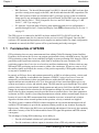
Figure 1: SPAN System Receiver
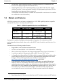
Figure 2: SPAN System IMUs
NovAtel's SPAN technology brings together two very different but complementary positioning and
navigation systems namely GPS and an Inertial Navigation System (INS). By combining the best
aspects of GPS and INS into one system, SPAN technology is able to offer a solution that is more
accurate and reliable than either GPS or INS could provide alone. The combined GPS/INS solution
has the advantage of the absolute accuracy available from GPS and the continuity of INS through
traditionally difficult GPS conditions.
The SPAN system consists of the following components:
•
NovAtel ProPak-V3 receivers - These receivers are capable of receiving and tracking
different combinations of GPS L1 C/A, L2C, L2 P(Y) and L5 code and carrier, GLONASS
(not available with SPAN) L1 and L2 code and carrier, and L-band (CDGPS and
OmniSTAR) on a maximum of 72 channels. SBAS support is standard on all OEMV family
receivers. OEMV adaptability offers multi-system, frequency, and size configurations for
any application requirement. Patented Pulsed Aperture Correlator (PAC) technology
combined with a powerful microprocessor make possible multipath-resistant processing.
Excellent acquisition and re-acquisition times allow this receiver to operate in environments
where very high dynamics and frequent interruption of signals can be expected. The OEMV
family also supports the timing requirements of the IMU and runs the real-time INS Kalman
SPAN Technology for OEMV User Manual Rev 7
19
Chapter 1
Introduction
filter.
•
IMU Enclosure - The Inertial Measurement Unit (IMU) is housed in the IMU enclosure that
provides a steady power supply to the IMU, and decodes and times the IMU output data. The
IMU itself consists of three accelerometers and 3 gyroscopes (gyros) so that accelerations
along specific axis and angular rotations can be measured. Several IMU types are supported
and are listed in Table 1, SPAN-Compatible Receiver and IMU Models on page 21 and
Table 17, IMU Type on page 82.
•
PC Software - Real-time data collection, status monitoring and receiver configuration is
possible through NovAtel’s Control and Display Unit (CDU) software utility, see Section 3.1
on page 33.
The GPS receiver is connected to the IMU enclosure with an RS-232 or RS-422 serial link. A
NovAtel GPS antenna must also be connected to the receiver to track GPS signals. Once the IMU
enclosure, GPS antenna and appropriate power supplies are attached, and a few simple configuration
commands are entered, the SPAN system will be up and running and ready to navigate.
1.1
Fundamentals of GPS/INS
GPS positioning observes range measurements from orbiting Global Positioning System Satellites.
From these observations, the receiver can compute position and velocity with high accuracy. NovAtel
GPS positioning systems have been established as highly accurate positioning tools, however GPS in
general has some significant restrictions, which limit its usefulness in some situations. GPS
positioning requires line of site view to at least four satellites simultaneously. If these criteria are met,
differential GPS positioning can be accurate to within a few centimetres. If however, some or all of
the satellite signals are blocked, the accuracy of the position reported by GPS degrades substantially,
or may not be available at all.
In general, an INS uses forces and rotations measured by an IMU to calculate position, velocity and
attitude. This capability is embedded in the firmware of OEMV-3 series of receivers. Forces are
measured by accelerometers in three perpendicular axes within the IMU and the gyros measure
angular rotation rates around those axes. Over short periods of time, inertial navigation gives very
accurate acceleration, velocity and attitude output. The INS must have prior knowledge of its initial
position, initial velocity, initial attitude, Earth rotation rate and gravity field. Since the IMU measures
changes in orientation and acceleration, the INS determines changes in position and attitude, but
initial values for these parameters must be provided from an external source. Once these parameters
are known, an INS is capable of providing an autonomous solution with no external inputs. However,
because of errors in the IMU measurements that accumulate over time, an inertial-only solution
degrades with time unless external updates such as position, velocity or attitude are supplied.
The SPAN system’s combined GPS/INS solution integrates the raw inertial measurements with all
available GPS information to provide the optimum solution possible in any situation. By using the
high accuracy GPS solution, the IMU errors can be modeled and mitigated. Conversely, the continuity
and relative accuracy of the INS solution enables faster GPS signal reacquisition and RTK solution
convergence.
The advantages of using SPAN technology are its ability to:
20
•
Provide a full attitude solution (roll, pitch and azimuth)
•
Provide continuous solution output (in situations when a GPS-only solution is impossible)
SPAN Technology for OEMV User Manual Rev 7
Introduction
1.2
Chapter 1
•
Provide faster signal reacquisition and RTK solution resolution (over stand-alone GPS
because of the tightly integrated GPS and INS filters)
•
Output high-rate (up to 100 or 200 Hz depending on your IMU model and other logging
selections) position, velocity and attitude solutions for high-dynamic applications, see also
Logging Restriction Important Notice on page 96
•
Use raw phase observation data (to constrain INS solution drift even when too few satellites
are available for a full GPS solution)
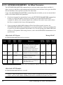
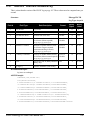
Models and Features
All SPAN system receivers are factory configurable for L1/L2 RTK capability and are compatible
with an IMU. See Table 1 for firmware model details.
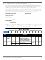
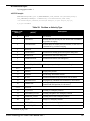
Table 1: SPAN-Compatible Receiver and IMU Models
Model Name
Max. Output Rate
Compatible IMUs
SW Model
IMU-H58
IMU-H62
100 Hz
HG1700-AG58
HG1700-AG62
V3RT2i
IMU-LN200
200 Hz
LN-200
200 and 400 Hz models
V3RT2j
IMU-FSAS-EI
200 Hz
iIMU-FSAS
V3RT2j
Each model is capable of multiple positioning modes of operation. For a discussion on GPS
positioning and enclosure details, please refer to the OEMV Family Installation and Operation User
Manual.
Each model has the following standard features:
•
•
Rugged shock, water, and dust-resistant enclosure
NovAtel's advanced OEMV L1/L2 GPS and PAC technology
•
•
•
Three bi-directional COM ports which support data transfer rates of up to 921,600 bits/s 1
A serial port capable of communication with an IMU. See also Table 1 above.
A Controller Area Network Bus (CAN Bus) which, is a rugged differential serial bus with a
protocol that provides services for processes, data and network management. Refer to the
Configure CAN for SPAN application note available on our Web site at
http://www.novatel.com/support/applicationnotes.htm as APN-046.
Field-upgradeable firmware (program software). What makes one model different from
another is software, not hardware. This unique feature means that the firmware can be
updated any time, anywhere, without any mechanical procedures whatsoever. For example, a
model with L1/L2-only capabilities can be upgraded to a model with L1/L2 RT-2 in only a
few minutes in your office (instead of the days or weeks that would be required if the
receiver had to be sent to a service depot). All that is required to unlock the additional
•
1.
Rates higher than 115, 200 are not standard on most PCs and may require extra PC hardware
SPAN Technology for OEMV User Manual Rev 7
21
Chapter 1
Introduction
features is a special authorization code. Refer to the OEMV Family Installation and
Operation User Manual for further details on this topic.
SPAN currently supports the Honeywell, iMAR and Litton IMUs. When using an IMU with SPAN, it
is housed in an enclosure with a PCB board to handle power, communication and data timing. See
Appendix A, Technical Specifications starting on page 47 for details.
22
SPAN Technology for OEMV User Manual Rev 7
Chapter 2
2.1
SPAN Installation
Hardware Description
The hardware setup consists of an OEMV receiver (see Figure 1 on page 19), an IMU (see Figure 2
on page 19), a GPS antenna, power and a radio link (if your application requires real time differential
operation). If your IMU enclosure and IMU have come separately, additional installation instructions
for installing the IMU can be found in Appendix E, HG1700 IMU Installation starting on page 135 or
Appendix F, LN-200 IMU Installation starting on page 140.
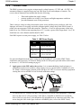
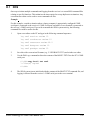
Your SPAN system receiver is ready for data collection. Figure 3 shows a typical set-up.
Rover
(
iIMU c able option)
Base
4
1
3
4
12V
4
Reference
1
2
3
4
5
6
7
5
Description
A ProPak-V3 receiver connected to a laptop for data storage
User-supplied NovAtel GPS antenna
LN-200, HG1700, or iIMU-FSAS IMU and IMU interface cable to the
port labelled AUX on the Propak-V3. With the iIMU, you must also
plug in the interface cable to the ProPak’s I/O port and to power.
User-supplied power supply
ProPak-V3 SPAN (1):
+9 to +18 V DC
ProPak-V3 base (6):
+9 to +18 V DC
Separate supply for IMU (3):
see Table 3 on page 27
User-supplied radio device to COM2
User-supplied base station OEMV Family receiver
User-supplied PC, for setting up and monitoring, to COM1
Figure 3: Basic Set-Up
SPAN Technology for OEMV User Manual Rev 7
23
Chapter 2
SPAN Installation
The sections that follows outline how to set up the system’s parts and cables. See Appendix A
Technical Specifications starting on page 47, and refer to the OEMV Family Installation and
Operation User Manual, for the NovAtel part numbers of ProPak-V3 cables and their pinouts.
Use a USB cable to log raw data. Serial communication is fine for configuring and monitoring the
SPAN through Hyperterminal or CDU. USB is required if you have a post-processing application
requiring 200 Hz IMU data. We also recommend you use CDU to collect the data.
2.1.1
SPAN System Receivers
Data storage, when using a ProPak-V3, is done using a laptop computer connected to the receiver
through either the serial or USB ports.
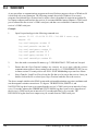
The back panel of the ProPak-V3 is shown in Figure 4. The ProPak-V3 uses DB9 COM connectors.
Figure 4: Receiver Enclosure Back Panel
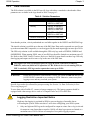
Table 2 shows a summary of the receiver’s back panel port names.
When you input a command that requires a port name referencing the third port, you must type in
COM3 for the ProPak-V3. This is true, even if the port is labelled AUX.
Table 2: Receiver Enclosure Back Panel Labels
SPAN Enclosure
ProPak-V3
2.1.2
Port Label
Description
9-18 VDC
Supply Voltage
COM1
COM1
COM2
COM2
AUX
COM3
I/O
I/O
GPS
Antenna
EXT OSC
External Oscillator
Cables and Ports
Refer to your receiver’s hardware manual for more information on its ports and cables (the OEMV
Family Installation and Operation User Manual).
24
SPAN Technology for OEMV User Manual Rev 7
SPAN Installation
Chapter 2
Each connector can be inserted in only one way, to prevent damage to both the receiver and the cables.
Furthermore, the connectors that are used to mate the cables to the receiver require careful insertion
and removal. Observe the following when handling the cables.
•
•
•
WARNING:
2.2
To insert a cable, make certain you are using the appropriate cable for the port - the
serial cable has a different connector (number of pins) than the power cable
Insert the connector until it is straight on and secure
To remove a cable, grasp it by the connector
DO NOT PULL DIRECTLY ON THE CABLE.
Hardware Set-Up
Review this section’s hardware set-up subsections and follow the numbered steps, in bold, to install
your SPAN system. The example graphics show the connections on the back of a ProPak-V3 receiver.
2.2.1
Mount Antenna
For maximum positioning precision and accuracy, as well as to minimize the risk of damage, ensure
that the antenna is securely mounted on a stable structure that will not sway or topple. Where possible,
select a location with a clear view of the sky to the horizon so that each satellite above the horizon can
be tracked without obstruction. The location should also be one that minimizes the effect of multipath
interference. For a discussion on multipath, please refer to the GNSS Reference Book.
1.
2.2.2
Mount the IMU and antenna securely to a vehicle. Ensure they cannot move due to dynamics
and that the distance and relative direction between them is fixed. See also Section 2.3.2, SPAN
IMU Configuration starting on page 28.
Mount IMU
Mount the IMU in a fixed location where the distance from the IMU to the GPS antenna phase center
is constant. Ensure that the orientation with respect to the vehicle and antenna is also constant.
For attitude output to be meaningful, the IMU should be mounted such that the positive Z-axis marked
on the IMU enclosure points up and the Y-axis points forward through the front of the vehicle, in the
direction of track.
Also, it is important to measure the distance from the IMU to the antenna (the Antenna Lever Arm),
on the first usage, on the axis defined on the IMU enclosure. See Section 3.3.4, Lever Arm Calibration
Routine starting on page 42. See also Appendix A, Technical Specifications starting on page 47 gives
dimensional drawings of the IMU enclosures.
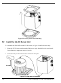
2.
Connect the IMU to the receiver using the IMU cable provided. For the ProPak-V3 receiver,
the IMU plugs into the port labelled AUX. See also Steps 1 and 2 in the SPAN IMU Configuration
section on page 28. The HG1700 and LN-200 plug directly from the ProPak-V3 to the IMU and
have a separate connector, and cable, for power. The iIMU-FSAS has a single connector whose
cable connects to the COM3 (labelled AUX) and I/O port of the ProPak-V3, and to power. See
also Step #3’s graphic on page 26.
SPAN Technology for OEMV User Manual Rev 7
25
Chapter 2
SPAN Installation
1.
The closer the antenna is to the IMU, the more accurate the position solution. Also, your
measurements when using the SETIMUTOANTOFFSET command must be as accurate
as possible, or at least more accurate than the GPS positions being used. For example, a
10 cm error in recording the antenna offset will result in at least a 10 cm error in
the output. Millimeter accuracy is preferred.
2.
The offset from the IMU to the antenna, and/or a user point device, must remain constant
especially for RTK or DGPS data. Ensure the IMU, antenna and user point device are
bolted in one position perhaps by using a custom bracket.
3.
The iIMU-FSAS IMU requires that COM3, labelled as AUX on the ProPak-V3, be in
RS-422 mode.
2.2.3
Connect COM Cables
The ProPak-V3 receiver incorporates an I/O port. This port may be part of an interconnected system
composed of devices that need to be synchronized with each other. For example, you could connect
the SPAN system to an aerial camera in such a way that the SPAN system recorded its position
whenever the shutter button was pressed.
The receivers have transistor-transistor-logic (TTL)-compatible I/O strobe lines. Typically, the I/O
strobe lines can be accessed by inserting the connector of an I/O strobe port cable into the I/O port.
The other end of the cable is provided without a connector so that you can provide an applicationspecific one. The jacket insulation is cut away slightly from the end but the insulation on each wire is
intact.
Refer to the hardware manual for your receiver for more information on signals, wiring and pin-out
information of the I/O port and its cable (the OEMV Family Installation and Operation User Manual).
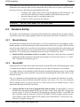
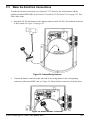
3.
Connect COM1 of the receiver to a computer COM port using a null modem cable.
iIMU
4.
26
LN-200 or
HG-1700
Connect the antenna to the antenna port on the receiver using an appropriate coaxial cable.
SPAN Technology for OEMV User Manual Rev 7
SPAN Installation
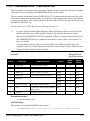
2.2.4
Chapter 2
Connect Power
The SPAN system receiver requires an input supply voltage between +12 VDC and +18 VDC. An
automotive adapter is supplied but power can come from a wall outlet adapter or batteries. The
receiver has an internal power module that does the following:
•
•
•
filters and regulates the supply voltage
protects against over-voltage, over-current, and high-temperature conditions
provides automatic reset circuit protection
There is always a drop in voltage between the power source and the power port due to cable loss.
Improper selection of wire gauge can lead to an unacceptable voltage drop at the SPAN system. A
paired wire run represents a feed and return line. Therefore, a 2-m wire pair represents a total wire
path of 4 m. For a SPAN system operating from a 12 V system, a power cable longer than 2.1 m (7 ft.)
should not use a wire diameter smaller than 24 AWG.
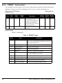
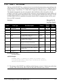
Each IMU requires its own power supply, see Table 3 below.
Table 3: IMU Power Supply
IMU
Power Requirement
LN-200
+12 to +28 V DC
iIMU-FSAS
+10 to +34 V DC
HG1700
+12 to +28 V DC
For pin-out information on the power connector on the ProPak-V3, refer to the OEMV Family
Installation and Operation User Manual. Details on the LN-200 power port and cables can be found
in Section A.1, LN-200 IMU starting on page 47.
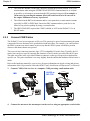
5.
Apply power to the IMU and to the receiver. It is recommended that a back-up battery is
placed between the receiver and its voltage supply to act as a power buffer if installed in a vehicle. When a vehicle engine is started, power can dip to 9.6 VDC or cut-out to ancillary equipment
causing the receiver and IMU to lose lock and calibration settings.
Voltage
Supply
+
-
For advanced users: You may also have a user point device such as video equipment. Connect the
device to the receiver’s I/O port using a cable that is compatible to both the receiver and the
device. Refer to your device’s documentation for information on its connectors and cables. The
arrow along the cable in the figure indicates a MARKIN pulse, refer to the OEMV Family
SPAN Technology for OEMV User Manual Rev 7
27
Chapter 2
SPAN Installation
Firmware Reference Manual, from the user device on the right to the ProPak-V3 I/O
port.
2.3
Software Configuration
2.3.1
GPS Configuration
The GPS configuration can be set up for different accuracy levels such as single point, SBAS, DGPS
and RTK (RTCA, RTCM, RTCM V3 and CMR). ProPak-V3 receivers can also be set up for Omnistar
HP, Omnistar VBS or CDGPS. Refer to the OEMV User Manuals for details on DGPS, RTK, L-band
or SBAS setup and operation.
With no additional configuration, the system operates in single point mode.
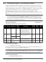
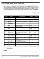
2.3.2
SPAN IMU Configuration
2.3.2.1
SPAN Configuration Manually
Follow these steps to enable INS as part of the SPAN system using software commands or see Section
2.3.2.2, SPAN Configuration with CDU on page 29 to see the alternate method using NovAtel’s
Control and Display Unit (CDU) software utility:
1.
Issue the INTERFACEMODE command to specify the receiver port connected to the IMU, see
Table 4 below and the INTERFACEMODE command on page 69.
2.
Issue the SETIMUTYPE command to specify the type of IMU being used, see Table 4 below
and the SETIMUTYPE command on page 81.
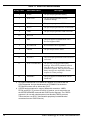
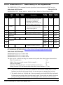
Table 4: Enable INS Commands
IMU Type
INTERFACEMODE Command
SETIMUTYPE Command
LN-200
interfacemode com3 imu imu off
setimutype imu_ln200
iIMU-FSAS
interfacemode com3 imarimu imarimu off
setimutype imu_imar_fsas a
HG1700
interfacemode com3 imu imu off
setimutype imu_hg1700_ag11, or
setimutype imu_hg1700_ag17, or
setimutype imu_hg1700_ag58, or
setimutype imu_hg1700_ag62
a. The iIMU-FSAS IMU requires that COM3, labelled as AUX on the ProPak-V3, be in
RS-422 mode. COM3 is factory-configurable for RS-232 or RS-422 mode.
28
SPAN Technology for OEMV User Manual Rev 7
SPAN Installation
Chapter 2
Basic configuration of the SPAN system is now complete. The inertial filter starts once the GPS
solution is solved and the IMU is connected.
1.
2.
3.
A GPS antenna must be connected and tracking satellites for operation.
Enter the INTERFACEMODE command with COM3 as the port value even if the ProPakV3 port is labelled AUX.
Issue the SETIMUTOANTOFFSET command to enter the distance from the IMU to the GPS
antenna, see page 80.
The offset between the antenna phase centre and the IMU axis must remain constant and be
known accurately (m). The X (pitch), Y (roll) and Z (azimuth) directions are clearly marked on
the IMU enclosure. The SETIMUTOANTOFFSET parameters are (where the standard deviation
fields are optional and the distances are measured from the IMU to the Antenna):
x_offset y_offset z_offset [x_stdev] [y_stdev] [z_stdev]
A typical RTK GPS solution is accurate to a few centimeters. For the integrated INS/GPS system
to have this level of accuracy, the offset must be measured to within a centimeter. Any offset error
between the two systems shows up directly in the output position. For example, a 10 cm error in
recording this offset will result in at least a 10 cm error in the output.
If it is impossible to measure the IMU to GPS antenna offset precisely, the offset can be estimated
by carrying out the Lever Arm Calibration Routine. See Section 3.3.4, Lever Arm Calibration
Routine on page 42.
2.3.2.2
SPAN Configuration with CDU
Follow these steps to enable INS as part of the SPAN system using the NovAtel CDU software utility:
The CDU screen shots in this manual are from CDU Version 3.3.0.3 and may differ from your
CDU version.
SPAN Technology for OEMV User Manual Rev 7
29
Chapter 2
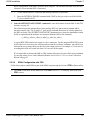
1.
30
SPAN Installation
SPAN basic configuration: Select Tools | SPAN Alignment Wizard from the main menu of CDU.
This wizard takes you through the steps to complete a coarse or fast alignment, select the type of
IMU and configure the receiver port, connected to the IMU, to accept IMU data:
SPAN Technology for OEMV User Manual Rev 7
SPAN Installation
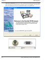
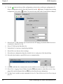
2.
Chapter 2
Optional SPAN calibration: Select Tools | SPAN Calibration Wizard from the main menu of
CDU. The wizard takes you through the steps to calibrate your lever arm and/or vehicle to body
rotation, as well as select the type of IMU and configure the receiver port connected to the IMU
and to accept data:
You need only run the Calibration Wizard if you need to calibrate the lever arm or vehicle to
frame angular offsets. It is not required for the SPAN filter to run.
2.3.2.3
Configuration for Alignment
A coarse alignment routine requires the vehicle to remain stationary for at least 1 minute. If that is not
possible, an alternate fast alignment routine is available. The fast or moving alignment is performed
by estimating the attitude from the GPS velocity vector and injecting it into the SPAN filter as the
initial system attitude. See also Section 3.3.1, System Start-Up and Alignment Techniques starting on
page 39 for more details on coarse and fast alignments.
SPAN Technology for OEMV User Manual Rev 7
31
Chapter 2
2.3.3
SPAN Installation
Configuration Command Summary
This section gives a brief recap of the commands necessary to get the SPAN system running.
1.
Issue the INTERFACEMODE command to specify the receiver port connected to the IMU, see
Table 4 on page 28 and the INTERFACEMODE command on page 69.
interfacemode com3 imu imu off
2.
Issue the SETIMUTYPE command to specify the type of IMU being used, see Table 4 on
page 28 and the SETIMUTYPE command on page 81.
setimutype imu_ln200
3.
Issue the SETIMUTOANTOFFSET command to enter the distance from the IMU to the GPS
antenna, see page 80.
setimutoantoffset 0.1 0.1 0.1 0.01 0.01 0.01
32
SPAN Technology for OEMV User Manual Rev 7
Chapter 3
SPAN Operation
Before operating your SPAN system, ensure that you have followed the installation and setup
instructions in Chapter 2, SPAN Installation starting on page 23.
You can use NovAtel’s CDU software to configure receiver settings and to monitor data in real-time,
between a rover SPAN system and base station.
SPAN system output is compatible with post-processing software from NovAtel's Waypoint Products
Group. Visit our Web site at www.novatel.com for details.
WARNING:
3.1
Ensure the Control Panel’s Power Settings on your PC are not set to go into
Hibernate or Standby modes. Data will be lost if one of these modes occurs during
a logging session.
Definition of Reference Frames Within SPAN
The reference frames that are most frequently used throughout this manual are the following:
• The Local-Level Frame
• The SPAN Body Frame
• The Enclosure Frame
• The Vehicle Frame
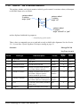
3.1.1
The Local-Level Frame (ENU)
The definition of the local level coordinate frame is as follows:
• z-axis– pointing up (aligned with gravity)
• y-axis– pointing north
• x-axis – pointing east
Figure 5: Local-Level Frame (ENU)
SPAN Technology for OEMV User Manual Rev 7
33
Chapter 3
3.1.2
SPAN Operation
The SPAN Body Frame
The definition of the SPAN body frame is as follows:
• z-axis– pointing up (aligned with gravity)
• y-axis– defined by how user has mounted the IMU
• x-axis – defined by how user has mounted the IMU
To determine your SPAN x-axis and y-axis, see Table 16 on page 79. This frame is also known as the
computation frame and is the frame where all the mechanization equations are computed.
3.1.3
The Enclosure Frame
The definition of the enclosure frame is defined on the IMU and represents how the sensors are
mounted in the enclosure. If the IMU is mounted with the z-axis (as marked on the IMU enclosure)
pointing up, the IMU enclosure frame is the same as the SPAN frame.
This origin of this frame is not the enclosure center, but the Center of Navigation (sensor center).
Figure 6: The Enclosure Frame
3.1.4
The Vehicle Frame
The definition of the vehicle frame is as follows:
• z-axis– points up through the roof of the vehicle perpendicular to the ground
• y-axis– points out the front of the vehicle in the direction of travel
• x-axis–completes the right-handed system (out the right-hand side of the vehicle
when facing forward
See the VEHICLEBODYROTATION Vehicle to SPAN frame Rotation on page 91 for information on
entering the rotation into the system and see the RVBCALIBRATE Vehicle to Body Rotation Control
on page 76 for information on calculating this rotation.
34
SPAN Technology for OEMV User Manual Rev 7
SPAN Operation
Chapter 3
Figure 7: Vehicle Frame
3.2
Communicating with the SPAN System
Once the receiver is connected to the PC, antenna, and power supply, install NovAtel’s OEMV PC
Utilities (CDU and Convert). You can find installation instructions in your receiver’s Quick Start
Guide. (Alternatively, you can use a terminal emulator program such as HyperTerminal to
communicate with the receiver.) Refer also to the CDU Help file for more details on CDU. The Help
file is accessed by choosing Help from the main menu in CDU.
Start CDU on your PC to enable communication:
1.
Launch CDU from the Start menu folder specified during the installation process. The default
location is Start | Programs | NovAtel OEMV | NovAtel CDU.
2.
Select Open.... from the Device menu.
3.
Select the New... button in the Open dialog box. The Options | Configuration dialog opens.
SPAN Technology for OEMV User Manual Rev 7
35
Chapter 3
SPAN Operation
4.
Use the
button at the top of the configurations selection box to add a new configuration. To
delete a configuration, select it from the list and click on the
button. To duplicate an existing
configuration, click on the
button. You can select any name in the list and edit it to change it.
5.
Select Serial, or USB, from the Type list and select the PC/laptop port, that the SPAN receiver is
connected to, from the Port list.
6.
Select 115200 from the Baud Rate list.
7.
Uncheck the Use hardware handshaking checkbox.
8.
Select OK to save the new device settings.
9.
Select the new configuration from the Available device configs area of the Open dialog.
10. Select the Open button to open SPAN receiver communications.
11. As CDU establishes the communication session with the receiver, a progress box is displayed.
12. Select Tools | Logging Control Window from the CDU main menu to control the receiver’s logging to files and serial ports. Refer to CDU’s on-line Help for more information.
13. Use the Console window to enter commands; Section 3.4, Data Collection for Post Processing on
page 45.
36
SPAN Technology for OEMV User Manual Rev 7
SPAN Operation
Chapter 3
If you have to power down your receiver, ensure that all windows, other than the Console
window, are closed in CDU and then use the SAVECONFIG command.
3.2.1
INS Window in CDU
CDU is a 32 bit Windows application. The application provides a graphical user interface to allow you
to set-up and monitor the operation of the SPAN system by providing a series of windows.
The INS Window in CDU is described below. Please refer to the OEMV Family Installation and
Operation User Manual for more details on CDU and other OEMV Family PC software programs.
•INS Window: The Position, Velocity and Attitude (roll, pitch and azimuth) sections display
data from the INSPVA log along with standard deviations calculated from the INSCOV log.
Information in the ZUPT (Zero Velocity Update) section reflects the current INSZUPT
command setting. The receiver uses the X,Y and Z Offset fields to specify an offset from the
IMU, for the output position and velocity of the INS solution, as specified by the
SETINSOFFSET command or CDU’s SPAN wizard. The INS Configuration/Status section
displays the IMU type, IMU Status and local date/time information. The dial is a graphical
display of the Roll, Pitch and Azimuth values indicated by an arrow on each axis.
3.3
Real-Time Operation
SPAN operates through the OEMV command and log interface. Commands and logs specifically
related to SPAN operation are documented in Appendices B and C of this manual respectively.
Real-time operation notes:
•
Inertial data does not start until time is set and therefore, the SPAN system does not function
unless a GPS antenna is connected with a clear view of the sky.
SPAN Technology for OEMV User Manual Rev 7
37
Chapter 3
SPAN Operation
•
The Inertial solution is computed separately from the GPS solution. The GPS solution is
available from the SPAN system through the GPS-specific logs even without SPAN running.
The integrated INS/GPS solution is available through special INS logs documented in
Appendix C of this manual.
•
The IMU solution is available at the maximum rate of output of the IMU (100 or 200 Hz).
Because of this high data rate, a shorter header format was created. These shorter header logs
are defined with an S (RAWIMUSB rather than RAWIMUB). We recommend you use these
logs instead of the standard header logs to save throughput on the COM port.
Status of the inertial solution can be monitored using the inertial status field in the INS logs, Table 5
below.
Table 5: Inertial Solution Status
Binary
ASCII
Description
0
INS_INACTIVE
IMU logs are present, but the
alignment routine has not started;
INS is inactive.
1
INS_ALIGNING
INS is in alignment mode.
2
INS_SOLUTION_NOTGOOD
The INS solution is still being
computed but the azimuth solution
uncertainty has exceed 2 degrees.
The solution is still valid but you
should monitor the solution
uncertainty in the INSCOV log. You
may encounter this state during
times when the GPS, used to aid the
INS, is absent. a
3
INS_SOLUTION_GOOD
The INS filter is in navigation mode
and the INS solution is good.
6
INS_BAD_GPS_AGREEMENT
The INS filter is in navigation mode,
and the GPS solution is suspected to
be in error.
This may be due to multipath or
limited satellite visibility. The inertial
filter has rejected the GPS position
and is waiting for the solution quality
to improve.
7
INS_ALIGNMENT_COMPLETE
The INS filter is in navigation mode,
but not enough vehicle dynamics
have been experienced for the
system to be within specifications.
a. See also the Frequently Asked Question appendix, question #8 on page 146
38
SPAN Technology for OEMV User Manual Rev 7
SPAN Operation
3.3.1
Chapter 3
System Start-Up and Alignment Techniques
The system requires an initial attitude estimate to start the navigation filter. This is called system
alignment. On start-up the system has no position, velocity or attitude information. When the system
is first powered up, the following sequence of events happens:
1.
The first satellites are tracked and coarse time is solved
2.
Enough satellites are tracked to compute a position
3.
Receiver “fine time” is solved, meaning the time on board the receiver is accurate enough to
begin timing IMU measurements
4.
Raw IMU measurements begin to be timed by the receiver and are available to the INS filter.
They are also available to you in the RAWIMU or RAWIMUS log, see page 123. The INS Status
field reports INS_INACTIVE.
5.
The inertial alignment routine starts and the INS Status field reports INS_ALIGNING.
6.
Alignment is complete and the INS Status field changes to INS_ALIGNMENT_COMPLETE.
The system transitions to navigation mode.
7.
The solution is refined using updates from GPS. Once the system is operating within
specifications and after some vehicle movement, the INS Status field changes to
INS_SOLUTION_GOOD. This indicates that the estimated azimuth standard deviation is below
2°. If it increases above 2°, the status changes to INS_SOLUTION_NOTGOOD.
3.3.1.1
Coarse Alignment
The coarse alignment is the default alignment routine for SPAN. The alignment starts as soon as a
GPS solution is available, the receiver has computed fine time and the IMU is connected and
configured. The vehicle must remain stationary for the alignment to happen. During the coarse
alignment, accelerometer and gyro measurements are averaged over a period of time to measure Earth
rotation and gravity. From these averaged measurements, initial estimates of roll, pitch and heading
are computed. Because the coarse alignment uses averaged sensor output, the vehicle must remain
stationary for the duration of the alignment, which is approximately 1 minute. The attitude estimates
solved by the alignment are larger than the system specified attitude accuracy and vary upon the
characteristics of the sensor and the geographic latitude of the system. Attitude accuracy converges
with motion after the coarse alignment is complete (see Section 3.3.2, Navigation Mode on page 40).
If the system is stationary for less than 1 minute, the coarse alignment finishes early, provided at least
5 stationary seconds were detected. The quality of the coarse alignment is poorer with stationary
durations of less than 1 minute.
3.3.1.2
Kinematic Alignment
If the preferred coarse alignment routine cannot be performed because the vehicle cannot remain
stationary for the length of time required, an alternate alignment routine is available. The kinematic or
moving alignment is performed by estimating the attitude from the GPS velocity vector and injecting
it into the SPAN filter as the initial system attitude.
Currently, this alignment routine is meant only for ground-based vehicles. The assumptions used for
the alignment may not hold for marine or airborne applications. For the kinematic alignment routine
to work optimally, the course-over-ground’s azimuth and pitch must match the IMU enclosure’s
SPAN Technology for OEMV User Manual Rev 7
39
Chapter 3
SPAN Operation
azimuth and pitch. (For example, a plane being blown in the wind has a a large ‘crab angle’ and the
course-over ground trajectory will not match the direction the IMU is pointing.)
Additional configuration parameters are necessary to enable the kinematic alignment. In order to
simplify this configuration it is strongly suggested that you mount the IMU in parallel to the vehicle
frame. The Y axis marked on the IMU enclosure, should point in the direction of travel.
Specify which IMU axes are most closely aligned with gravity using the SETIMUORIENTATION
command. If the IMU is mounted with the Z-axis up and the Y-axis pointing in the direction of travel,
then the command would be:
SETIMUORIENTATION 5
Specify the angular offsets between the SPAN frame and the vehicle frame (known as vehicle/body
rotation or RVB) using the VEHICLEBODYROTATION command, see page 91. If the IMU is
mounted coincidentally with the vehicle frame (defined as z up and y pointing in the direction of
travel), then the command would be:
VEHICLEBODYROTATION 0 0 0
Alternatively, solve the vehicle to IMU frame angular offsets using the RVBCALIBRATE routine. See
also Section 3.3.5, Vehicle to SPAN frame Angular Offsets Calibration Routine on page 43.
The kinematic alignment begins when the receiver has a good GPS position, fine time is solved, the
configuration parameters have been set and a GPS velocity of at least 1.15 (~ 4 km/h) m/s is observed.
During kinematic alignment, keep the vehicle roll at less then 10°. Straight line driving is best.
The accuracy of the initial attitude of the system following the kinematic alignment varies and
depends on the dynamics of the vehicle and the accuracy of the RVB estimates. The attitude accuracy
will converge to within specifications once some motion is observed by the system. This transition
can be observed by monitoring the INS Status field in the INS logs.
3.3.1.3
Manual Alignment
Manually enter the attitude information using the SETINITATTITUDE, or SETINITAZIMUTH,
commands. Details of these commands start on page 83.
3.3.2
Navigation Mode
Once the alignment routine has successfully completed, SPAN enters navigation mode.
SPAN computes the solution by accumulating velocity and rotation increments from the IMU to
generate position, velocity and attitude. SPAN models system errors by using a Kalman filter. The
GPS solution, phase observations and automatic zero velocity updates (ZUPTs) provide updates to the
Kalman filter. When a sensor is connected to the system, wheel displacement updates are also used in
the filter.
Following the alignment the attitude is coarsely defined, especially in heading. Vehicle dynamics,
specifically turns, stops and starts, allow the system to observe the heading error and allows the
heading accuracy to converge. Three to five changes in heading should be sufficient to resolve the
heading accuracy. The INS Status field changes to INS_SOLUTION_GOOD once convergence is
complete. If the attitude accuracy decreases, the INS Status field changes to
INS_SOLUTION_NOTGOOD. When the accuracy converges again, the INS status continues as
INS_SOLUTION_GOOD.
40
SPAN Technology for OEMV User Manual Rev 7
SPAN Operation
3.3.3
Chapter 3
Data Collection
The INS solution is available in the INS-specific logs with either a standard or short header. Other
parameters are available in the logs shown in Table 6 on page 41:
Table 6: Solution Parameters
Parameter
Log
Position
INSPOS or INSPOSS
INSPVA or INSPVAS
Velocity
INSVEL or INSVELS
INSSPD or INSSPDS
INSPVA or INSPVAS
Attitude
INSATT or INSATTS
INSPVA or INSPVAS
Solution Uncertainty
INSCOV or INSCOVS
Note that the position, velocity and attitude are available together in the INSPVA and INSPVAS logs.
The inertial solution is available up to the rate of the IMU data. Data can be requested at a specific rate
up to the maximum IMU output rate, or can be triggered by the mark input trigger at rates up to 20 Hz.
The GPS-only solution is still available through the GPS-only logs such as RTKPOS, PSRPOS and
OMNIHPPOS. When running SPAN, rates of non-INS logs should be limited to a maximum rate of 5
Hz. Refer to the OEMV Family Firmware Reference Manual for more details on these logs. INS-only
data logging and output can be at rates of up to the rate of the IMU data.
The highest rate that you should request GPS logs (RANGE, BESTPOS, RTKPOS,
PSRPOS, and so on) while in INS operation is 5 Hz. If the receiver is not running INS (no
IMU is attached), GPS logs can be requested at rates up to 20 Hz.
WARNING:
Ensure that all windows, other than the Console, are closed in CDU and then use the
SAVECONFIG command to save settings in NVM. Otherwise, unnecessary data
logging occurs and may overload your system.
Specific logs need to be collected for post-processing. See Section 3.4, Data Collection for Post
Processing on page 45.
To store data with a ProPak-V3, connect a laptop computer to it. The laptop computer should be
equipped with a data storage device such as a Compact Flash Card, CD or MP3 disc.
Logging Restriction Important Notice
High-rate data logging is regulated in SPAN to prevent logging of unusable data or
overloading the system. Please note these 3 rules when configuring your SPAN system:
1.
Only one high-rate INS log can be configured for output at a time. Once a log is selected
for output at a rate faster than or equal to 100 Hz, all other log requests are limited to a
maximum rate of 50 Hz. Below are examples of acceptable logging requests:
SPAN Technology for OEMV User Manual Rev 7
41
Chapter 3
SPAN Operation
LOG RAWIMUSB ONNEW
LOG INSPVASB ONTIME 0.02
(100 or 200 Hz depending on the IMU)
(acceptable 50 Hz logging)
The following is rejected because RAWIMU has already been requested at 100/200 Hz:
LOG INSPOSSB ONTIME 0.01 (100 Hz request)
Below is another example set of acceptable logging requests:
LOG INSPOSSB ONTIME 0.01 (100 Hz request)
LOG INSVELSB ONTIME 0.02 (50 Hz request)
The following are rejected in this case because INSPOSSB has already been requested at
a high rate.
LOG RAWIMUSB ONNEW
(100 Hz request)
LOG INSATTSB ONTIME 0.005 (200 Hz request)
3.3.4
2.
RAWIMU and RAWIMUS logs are only available with the ONNEW or ONCHANGED
trigger. These logs are not valid with the ONTIME trigger. The raw IMU observations
contained in these logs are sequential changes in velocity and rotation. As such, you can
only use them for navigation if they are logged at their full rate. See details of these log
starting on page 123.
3.
In order to collect wheel sensor information, useful in post-processing, the
TIMEDWHEELDATA log should only be used with the ONNEW trigger. See also page
129 for details on this log.
Lever Arm Calibration Routine
Each time the system is re-mounted on a vehicle, or the IMU or antenna is moved on the vehicle, the
lever arm must be redefined either through manual measurement or through calibration.
We recommend that you measure the lever arm using survey methodology and equipment, for
example, a total station. Only use calibrations when precise measurement of the lever arm is not
possible.
The lever arm calibration routine should only be used when the receiver is operating in RTK mode.
Initial estimates and uncertainties for the lever arm are entered using the SETIMUTOANTOFFSET
command, see page 80. The calibration routine uses these values as the starting point for the lever arm
computation.
The steps involved in the calibration are:
42
1.
Power the receiver and the IMU, see the IMU choices and their technical specifications starting
on page 47.
2.
Configure the RTK corrections and make sure that the BESTGPSPOS log, see page 97, reports a
good RTK solution.
3.
Configure the IMU, see Section 2.3.2, SPAN IMU Configuration on page 28.
SPAN Technology for OEMV User Manual Rev 7
SPAN Operation
Chapter 3
4.
Set the orientation of your installed IMU using the SETIMUORIENTATION command, see page
77.
5.
Enter the initial estimate for the lever arm using the SETIMUTOANTOFFSET command, see
page 80.
6.
Specify the limits of the calibration through the LEVERARMCALIBRATE command, see page
73. The calibration can be limited by time or accuracy of the lever arm. It is recommended that
the calibration is limited by a minimum of 300 seconds.
7.
To monitor the calibration, log BESTLEVERARM, see page 104, using the ONCHANGED
trigger.
8.
Remain stationary long enough for the coarse alignment to finish. The alignment is complete
when the INS status changes to INS_ALIGNMENT_COMPLETE. See also Table 5 on page 38.
9.
Start to move the system. The lever arm is not observable while the system is stationary.
Immediately, drive a series of manoeuvres such as figure eights. The turns should alternate
between directions, and you should make an equal number of turns in each direction. Some height
variation in the route is also useful for providing observability in the Z-axis. When the calibration
is complete, either because the specified time has passed or the accuracy requirement has been
met, the BESTLEVERARM log outputs the solved lever arm.
The lever arm is saved automatically in non-volatile memory. If the IMU or GPS antenna are remounted, the calibration routine should be re-run to compute an accurate lever arm.
3.3.5
Vehicle to SPAN frame Angular Offsets Calibration Routine
Kinematic fast alignment requires that the angular offset between the vehicle and IMU SPAN frame is
known approximately. If the angles are simple (that is, a simple rotation about one axis) the values can
easily be entered manually through the VEHICLEBODYROTATION command, see page 91. If the
angular offset is more complex (that is, rotation is about 2 or 3 axis), then the calibration routine
provides a more accurate estimation of the values. As with the lever arm calibration, the vehicle to
SPAN frame angular offset calibration requires RTK GPS. The steps for the calibration routine are:
1.
Apply power to the receiver and IMU, see the IMU choices and their technical specifications
starting on page 47.
2.
Configure the IMU, see Section 2.3.2, SPAN IMU Configuration on page 28.
3.
Ensure that an accurate lever arm has been entered into the system either manually or through a
lever arm calibration, see page 42.
4.
Allow the system to complete a coarse alignment, see page 39.
5.
Enable the vehicle to body calibration using the RVBCALIBRATE ENABLE command, see page
76.
6.
Start to move the system. As with the lever arm calibration, movement of the system is required
for the observation of the angular offsets.
SPAN Technology for OEMV User Manual Rev 7
43
Chapter 3
SPAN Operation
Drive a series of manoeuvres such as figure eights if the driving surface is not level, or a straight
course if on level ground (remember that most roads have a crown resulting in a constant roll of a
few degrees). Avoid driving on a surface with a constant, non-zero, slope to prevent biases in the
computed angles. Vehicle speed must be greater than 5 m/s (18 km/hr) for the calibration to
complete.
7.
When the uncertainties of the offsets are low enough to be used for a fast alignment, the
calibration stops and the VEHICLEBODYROTATION log, see page 130, is overwritten with the
solved values. To monitor the progress of the calibration, log VEHICLEBODYROTATION using
the ONCHANGED trigger.
The rotation parameters are saved in NVM for use on start-up in case a fast-alignment is required.
Each time the IMU is re-mounted this calibration should be performed again. See also Sections 3.3.1.1
and 3.3.1.2 on page 39 for details on coarse and fast alignment.
WARNING: After the RVBCALIBRATE ENABLE command is entered, there are no vehiclebody rotation parameters present and a kinematic alignment is NOT possible.
Therefore this command should only be entered after the system has performed
either a static or kinematic alignment and has a valid INS solution.
The solved rotation values are used only for a rough estimate of the angular offsets between the
IMU and vehicle frames. The offsets are used when aligning the system while in motion (see
Section 3.3.1, System Start-Up and Alignment Techniques starting on page 39). The angular offset
values are not applied to the attitude output, unless the APPLYVEHICLEBODYROTATION
command is enabled, see page 65.
3.3.6
SPAN Wheel Sensor Messages
The SPAN system supports wheel sensor inputs. Wheel sensor information is input to the receiver
through the WHEELVELOCITY message in either ASCII or binary format. The message is sent with
the port interface mode set to NovAtel. See the INTERFACEMODE command examples in Section
2.3.2, SPAN IMU Configuration on page 28. For HG1700 and LN-200 users, the wheel velocity
commands must be created and sent to the SPAN receiver at 1 Hz. For iIMU-FSAS users, the wheel
sensor is integrated via the FSAS IMU, and wheel velocity commands are not required. See also
iIMU-FSAS Odometer Cabling on page 56 of the Technical Specifications appendix.
3.3.6.1
Measurement Timing and Frequency
Typical wheel sensor hardware accumulates wheel ticks constantly as the wheel rotates. The SPAN
interface is configured to expect wheel sensor tick counts at a rate of 1Hz, aligned with the GPS evensecond boundaries. The GPS second boundary is available from the OEMV 1PPS pulse. This pulse
should be used to trigger the wheel sensor hardware to send the accumulated tick count back to the
receiver through the WHEELVELOCITY message, see page 93.
44
SPAN Technology for OEMV User Manual Rev 7
SPAN Operation
Chapter 3
SPAN does not accumulate raw measurement ticks from a wheel sensor device. Additional
hardware is required to accumulate the tick counts and pass the accumulated count to the SPAN
system at 1Hz, triggered by the 1PPS. Refer also to our application note on Using a Wheel Sensor
with SPAN, NovAtel part number APN-036 (available on our Web site at http://
www.novatel.com/support/applicationnotes.htm).
3.3.6.2
Wheel Sensor Update Logic
The SPAN system uses the WHEELVELOCITY command to apply a time to the message based on
the time of the last 1PPS pulse and the latency reported in the log. This timed data is passed to the
INS/GPS Kalman filter to perform the update. The timed data is also available through the
TIMEDWHEELDATA log, see page 129. The TIMEDWHEELDATA log can be used for applying
wheel sensor updates in post-processing.
The SPAN Kalman filter uses sequential TIMEDWHEELDATA logs to compute a distance traveled
between update intervals (1Hz). This information can be used to constrain free-inertial drift during
times of poor GPS visibility. The filter also contains a state for modeling the circumference of the
wheel as it may change due to hardware changes or environmental conditions.
The modeled wheel circumference is available in the WHEELSIZE log, see page 131. Information on
how the wheel sensor updates are being used is available in the INSUPDATE log, see page 117.
3.3.6.3
iMAR Wheel Sensor Interface for iIMU-FSAS users
If you have the iMAR iMWS (Magnetic Wheel Speed Sensor and Convertor), the wheel sensor
information is sent to the OEMV along with the raw IMU data. You can integrate other wheel sensor
hardware with the iIMU-FSAS. The Corrsys Datron wheel pulse transducer is used as an example, see
Section A.2.2, iIMU-FSAS Odometer Cabling on page 56.
The accumulated wheel sensor counts are available by logging the timed wheel data log with the
onchanged trigger:
log timedwheeldatab onnew
Set parameters for your installation using the SETWHEELPARAMETERS command, see page 90.
3.4
Data Collection for Post Processing
Some operations such as aerial measurement systems do not require real-time information from
SPAN. These operations are able to generate the position, velocity or attitude solution post-mission in
order to generate a more robust and accurate solution than is possible in real-time.
In order to generate a solution in post-processing, data must be simultaneously collected at a base
station and each rover. The following logs must be collected in order to successfully post process data
SPAN Technology for OEMV User Manual Rev 7
45
Chapter 3
SPAN Operation
From a base:
•
RANGECMPB ONTIME 1
•
RAWEPHEMB ONNEW
From a rover:
•
RANGECMPB ONTIME 1
•
RAWEPHEMB ONNEW
•
RAWIMUSB ONNEW
Post processing is performed through the Waypoint Inertial Explorer software package available from
from NovAtel's Waypoint Products Group. Visit our Web site at www.novatel.com for details.
The highest rate that you should request GPS logs (RANGE, BESTPOS, RTKPOS, PSRPOS, and
so on) while in INS operation is 5 Hz. If the receiver is not running INS (no IMU is attached),
GPS logs can be requested at rates up to 20 Hz.
46
SPAN Technology for OEMV User Manual Rev 7
Appendix A Technical Specifications
This appendix details the technical specifications of the IMUs. Refer to your SPAN system
enclosure’s hardware manual for more information on its technical specifications, performance and
cables (the OEMV Family Installation and Operation User Manual).
A.1
LN-200 IMU
Table 7: LN-200 IMU Specifications
PHYSICAL
IMU Enclosure Size
IMU Size
13.3
IMU Weight
135 mm x 153 mm x 130 mm (5.315” x 6.024” x 5.118”)
89 mm 143.7
D x 85 mm H (3.504” D x 3.346” H)
~3 kg (6.6 lb.)
MECHANICAL DRAWINGS
8.1
4 PLCS.
13.3 76.2
76.8
IMU Enclosure Center
143.7
82.4
Navigation Center
134.6
8.1
4 PLCS.
76.8
Enclosure Center
76.2
SCALE 0.800
134.6
70.7
Navigation Center
R92.9
76.3
IMU Enclosure Center
70.7
Navigation Center
82.4
Navigation Center
SCALE 0.800
R92.9
76.3
Enclosure Center
Figure 8: LN-200 IMU Enclosure Top/Bottom Dimensions and Centre of Navigation
SPAN Technology for OEMV User Manual Rev 7
47
Figure 9: LN-200 Enclosure Side Dimensions
Scale: 0.800
13 Pin
3 Pin
Note: The Center of
Navigation offsets,
shown on the LN-200
label, are for the
internal IMU and are
different than for the
enclosure center. The
measurements for the
enclosure center are
labelled as:
IMU Enclosure Center
in this figure and
Figure 5.
SPAN Technology for OEMV User Manual Rev 7
48
A.1.1
LN-200 IMU Interface Cable
The NovAtel part number for the LN-200 IMU interface cable is 01017375 (Figures 10 and 11
below). The IMU interface cable supplied enables input and output between the IMU and the receiver.
Figure 10: LN-200 Interface Cable
Deutsch 13-Pin to IMU
S1
S2
DB-9 Female to Receiver
N/C
PAIRED
S3
S3
S7
S4
N/C
S5
S5
S6
N/C
S7
PAIRED
S8
S9
S8
S2
2 WIRES
S1
S9
S6
S10
N/C
S11
PAIRED
N/C
S12
N/C
S13
N/C
Figure 11: IMU Interface Cable Pin-Out (ProPak-V3)
SPAN Technology for OEMV User Manual Rev 7
49
A.1.2
LN-200 IMU Power Adapter Cable
The power adapter cable, NovAtel part number 01017821, supplied with the LN-200 provides a
convenient means for supplying +12 VDC while operating from a 12V source. Figure 12 shows the
cable and Figure 13 the wiring diagram of the 12V adapter.
The output of the power adapter uses a 3-pin Deutsch socket (Deutsch part number: 59064-09-98SN).
This cable plugs directly into the 3-pin port on the front of the LN-200 enclosure.
Figure 12: LN-200 Power Cable
2
1
2
6
3
A
4
B
C
5
Reference
Description
Reference
Description
1
3-pin Deutsch connector
A
Black
2
12V adapter
B
Red
3
Outer contact
C
White/Natural
4
3 amp slow-blow fuse
5
Center contact
6
Foil shield
Figure 13: IMU Power Cable Pin-Out
50
SPAN Technology for OEMV User Manual Rev 7
A.1.3
IMU Performance
PERFORMANCE (IMU)
IMU-LN200
A.1.4
Gyro Input Range
Gyro Rate Bias
Gyro Rate Scale Factor
Angular Random Walk
Accelerometer Range
Accelerometer Linearity
Accelerometer Scale Factor
Accelerometer Bias
± 1000 degrees/s
1°/hr
100 ppm
0.07 degrees/rt-hr
± 40 g
300 ppm
0.3 mg
Electrical and Environmental
ELECTRICAL
IMU Power Consumption
16 W (max)
IMU Input Voltage
+12 to +28 V DC
Receiver Power Consumption
ProPak-V3
2.8 W (typical)
System Power Consumption
ProPak-V3
14.8 W (typical)
Data Connector on Enclosure
13-pin Deutsch P/N 59065-11-35PF a
Power Connector on Enclosure 3-pin Deutsch P/N 59065-09-98PN a
+6 to +18 VDC
IMU Interface
RS-232 or RS-422
ENVIRONMENTAL (LN-200 IMU)
Temperature
Operating
Storage
Humidity
95% non-condensing
-30°C to +60°C (-22°F to 140°F)
-45°C to +80°C (-49°F to 176°F)
a. For replacement connectors on the interface or power cables, see Section H.3,
Manufacturer’s Part Numbers on page 147.
SPAN Technology for OEMV User Manual Rev 7
51
A.2
iIMU-FSAS
Table 8: iIMU-FSAS Specifications
PHYSICAL
IMU Size
128 mm x 128 mm x 104 mm (5.04” x 5.04” x 4.09”)
IMU Weight
2.1 kg (4.63 lb.)
MECHANICAL DRAWINGS aA
35.5
Figure 14: iIMU-FSAS Top/Bottom Dimensions
a. See Figure 16 on page 54 for the centre of navigation dimensions
b. Dimensions are in mm.
52
SPAN Technology for OEMV User Manual Rev 7
Figure 15: iIMU-FSAS Enclosure Side Dimensions
SPAN Technology for OEMV User Manual Rev 7
53
Figure 16: iIMU-FSAS Centre of Navigation
54
SPAN Technology for OEMV User Manual Rev 7
A.2.1
iIMU-FSAS Interface Cable
The NovAtel part number for the 1 m iIMU-FSAS interface cable is 60723086 for the ProPak-V3 (see
Table 9 below and Figure 19, iIMU-FSAS Interface Cable on page 58). See also Section A.2.2, iIMUFSAS Odometer Cabling on page 56 if applicable.
The IMU interface cable supplied, provides power to the IMU from an external power source, and
enables input and output between the receiver and IMU.
Table 9: IMU Interface Cable Pin-Out
MIL-C38999 III
Connector Pin
Function
1
PGND
2
ODO_AN
3
VIN
4
ODO_A
5-6
Power
4 mm
plugs
Female
DB9 to
COM3
Male
DB9
to I/O
Male
DB9 to
ODO
Color: black
Label: PGND
Comments
Power ground
7
Color: red
Label: 10-34 VDC
Odometer input A(-),
opto-coupler: +2 to +6 V
(RS-422 compatible)
+10 to +34 VDC
6
Odometer input A(+),
opto-coupler: +2 to +6 V
(RS-422 compatible)
Reserved
7
DAS
1 and 6
Shielded data acquisition
signal (LVTTL to VARF)
8
Reserved
9
DAS_GND
9
Shielded ground
reference for data
acquisition and control
signals
10
Reserved
11
DON
8
Twisted pair; serial data
output signal / RS-422(-)
12
DO
2
Twisted pair; serial data
output signal / RS-422(+)
13
Reserved
14
DGND
5
Digital ground
15
DGND
5
16
ODO_B
3
Odometer input B(+),
opto-coupler: +2 to +6 V
(RS-422 compatible)
17
ODO_BN
1
Odometer input B(-),
opto-coupler: +2 to +6 V
(RS-422 compatible)
Digital ground
Continued on page 56
SPAN Technology for OEMV User Manual Rev 7
55
MIL-C38999 III
Connector Pin
A.2.2
Function
Power
4 mm
plugs
Female
DB9 to
COM3
Male
DB9
to I/O
Male
DB9 to
ODO
Comments
18
Reserved
19
DI
3
Twisted pair; serial data
in / RS-422(+)
20
DIN
7
Twisted pair; serial data
in / RS-422(-)
21
SW_ON_SIG
Connected to Pin 3;
switch IMU signal
ON/OFF (voltage applied
= ON)
+4 to +34 V
22
SWON_GND
Connected to Pin 1;
ground for IMU signal
ON
iIMU-FSAS Odometer Cabling
The iIMU-FSAS with the –O wheel sensor option provides wheel sensor input from the Distance
Measurement Instrument (DMI) through the DB-9 connector labelled “ODO” on the IMU interface
cable. The IMU data goes through the IMU and then into the SPAN receiver through the serial
communication line.
There are two DMI products that are compatible with the iIMU-FSAS system:
• iMWS-V2 (Magnetic Wheel Sensor) from iMAR
- A magnetic strip and detector are installed inside the wheel. The signal then
goes through a box that translates the magnetic readings into pulses that are
then passed through the cable into the ODO connector on the IMU cable. See
also Figure 18 below.
• WPT (Wheel Pulse Transducer) from Corrsys Datron
- A transducer traditionally fits to the outside of a non-drive wheel. A pulse is
then generated from the transducer which is fed directly to the ODO
connector on the IMU cable.See also Figure 17 on page 57.
56
SPAN Technology for OEMV User Manual Rev 7
The iMAR iMWS-V2 sensor is on the inside
of the wheel so that all you can see in the
vehicle is the grey signal converter box.
Figure 17: Corrsys Datron WPT
Figure 18: iMAR iMWS Pre-Installed
The WPT mounts to the wheel lug nuts via
adjustable mounting collets. The torsion
protection rod, which maintains rotation
around the wheel axis, affixes to the vehicle
body with suction cups. Refer to the Corrsys
Datron WPT user manual for mounting
instructions.
iMAR provides a sensor that operates with a
magnetic strip glued inside the rim of a non-drive
wheel and a special detector (iRS) mounted on
the inside of the wheel (the disk of the wheel
suspension, brake cover or brake caliper holder).
Details are shown in the installation hints
delivered with the system.
The NovAtel IMU interface cable, with ODO, is the same as that in Section A.2.1 but with some of the
reserved pins having odometer uses. It still provides power to the IMU from an external source, and
enables input and output between the receiver and IMU. Once installed, see also SPAN Wheel Sensor
Messages on page 44.
1.
2.
The DMI runs only one output line (A).
SPAN specifies that the maximum pulse frequency for a wheel sensor input to SPAN is 1
MHz.
You can use our interface cable, with the ODO connector, to plug directly into the iMWS. With the
WPT, first modify the cable at the WPT end. The cable modification is shown in Table 10 on page 58.
Connect the female DB9 connector to the male ODO end of the iIMU-FSAS interface cable.
SPAN Technology for OEMV User Manual Rev 7
57
Table 10: Cable Modification for Corrsys Datron WPT
8-pin M12 connector on
the Corrsys Datron cable a, b
Female DB9
connector
Pin 1
GND
White
No change
Pin 2
+UB (Input Power)
Brown
Pin 3
Signal A
Green
6
Pin 4
Signal A inverted
Yellow
7
Pin 5
Signal B
Grey
3
Pin 6
Signal B inverted
Pink
1
Pin 7
Reserved
No change
Pin 8
a. Pin 2 is wired to a red banana plug (Power in) and Pin 1 is wired
to a black banana plug (Power return) so the WPT needs power
to operate (+10 to +30 V). Solder the shield on the WPT cable to
the female DB9 housing.
b. This modification is for the Corrsys Datron WPT 8-pin M12plug cable number 14865.
Figure 19: iIMU-FSAS Interface Cable
58
SPAN Technology for OEMV User Manual Rev 7
A.2.3
IMU Performance
PERFORMANCE (IMU)
iIMU-FSAS
A.2.4
Gyro Input Range
Gyro Rate Bias
Gyro Rate Scale Factor
Angular Random Walk
Accelerometer Range
Accelerometer Linearity
Accelerometer Scale Factor
Accelerometer Bias
± 500 degrees/s
0.75°/hr
300 ppm
0.1 degrees/sq rt hr
± 5 g (± 20 g optional)
400 ppm
1.0 mg
Electrical and Environmental
ELECTRICAL
IMU Power Consumption
16 W (max)
IMU Input Voltage
+10 to +34 V DC
Receiver Power Consumption
ProPak-V3
2.8 W (typical)
System Power Consumption
ProPak-V3
14.8 W (typical)
Data Connector
MIL-C-38999-III
Power Connector
MIL-C-38999-III (same as data connector)
IMU Interface
RS-422
ENVIRONMENTAL (iIMU-FSAS)
Temperature
Operating
Storage
Humidity
95% non-condensing
SPAN Technology for OEMV User Manual Rev 7
-40°C to +71°C (-40°F to 160°F)
-40°C to +85°C (-40°F to 185°F)
59
A.3
HG1700 IMU
Table 11: HG1700 IMU Specifications
PHYSICAL
IMU Enclosure Size
193 mm x 167 mm x 100 mm (7.6” x 6.6” x 3.9”)
IMU Size
160 mm x 160 mm x 100 mm (6.3” x 6.3” x 3.9”)
IMU Weight
3.4 kg (7.49 lb.)
MECHANICAL DRAWINGS
Note: The Center of
Navigation, shown
on the HG1700 label,
for the internal IMU
is the same as the
enclosure’s center.
The enclosure center
measurements are
labelled as:
IMU Enclosure Center
in this figure.
Figure 20: HG1700 Top/Bottom Dimensions
60
SPAN Technology for OEMV User Manual Rev 7
Figure 21: HG1700 Enclosure Side Dimensions
13 Pin
3 Pin
Scale: 0.600
Note: The Center of
Navigation, shown
on the HG1700 label,
for the internal IMU
is the same as the
enclosure’s center.
The enclosure center
measurements are
labelled as:
IMU Enclosure Center
in this figure.
61
SPAN Technology for OEMV User Manual Rev 7
A.3.1
HG1700 IMU Interface Cable
The IMU interface cable supplied, provides power to the IMU from an external power source, and
enables input and output between the receiver and IMU. It is the same as the cable supplied with the
LN-200, see Figure 10 on page 49.
A.3.2
IMU Performance
PERFORMANCE (IMU)
62
IMU-H58
Gyro Input Range
Gyro Rate Bias
Gyro Rate Scale Factor
Angular Random Walk
Accelerometer Range
Accelerometer Linearity
Accelerometer Scale Factor
Accelerometer Bias
± 1000 degrees/s
1.0 degree/hr
150 ppm
0.125 degrees/rt hr
± 50 g
500 ppm
300 ppm
1.0 mg
IMU-H62
Gyro Input Range
Gyro Rate Bias
Gyro Rate Scale Factor
Angular Random Walk
Accelerometer Range
Accelerometer Linearity
Accelerometer Scale Factor
Accelerometer Bias
± 1000 degrees/s
5.0 degrees/hr
150 ppm
0.5 degrees/rt-hr
± 50 g
500 ppm
300 ppm
3.0 mg
SPAN Technology for OEMV User Manual Rev 7
A.3.3
Electrical and Environmental
ELECTRICAL
IMU Power Consumption
IMU-H58: 9 W (max)
IMU-H62: 8 W (max)
IMU Input Voltage
+12 to +28 V DC
Receiver Power Consumption
ProPak-V3
2.8 W (typical)
System Power Consumption
ProPak-V3
14.8 W (typical)
Data Connector on Enclosure
13-pin Deutsch P/N 59065-11-35PF a
Power Connector on Enclosure 3-pin Deutsch P/N 59065-09-98PN a
+6 to +18 VDC
IMU Interface
RS-232 or RS-422
Temperature
Operating
Storage
Humidity
95% non-condensing
ENVIRONMENTAL (IMU)
-30°C to +60°C (-22°F to 140°F)
-45°C to +80°C (-49°F to 176°F)
a. For replacement connectors on the interface and power cables, see Section H.3,
Manufacturer’s Part Numbers on page 147.
SPAN Technology for OEMV User Manual Rev 7
63
Appendix B INS Commands
The INS-specific commands are described further in this chapter.
For information on other available commands, refer to the OEMV Family Firmware Reference
Manual.
B.1
Using a Command as a Log
All NovAtel commands may be used for data input, as normal, or used to request data output (a
unique OEMV Family feature). INS-specific commands may be in Abbreviated ASCII, ASCII, or
Binary format.
Consider the lockout command (refer to the OEMV Family Firmware Reference Manual) with the
syntax:
lockout prn
You can put this command into the receiver to de-weight an undesirable satellite in the solution, or
you can use the lockout command as a log to see if there is a satellite PRN that has already been
locked out. In ASCII, this might be:
log com1 lockouta once
Notice the ‘a’ after lockout to signify you are looking for ASCII output.
The highest rate that you should request GPS logs (RANGE, BESTPOS, RTKPOS, PSRPOS, and
so on) while in INS operation is 5 Hz. If the receiver is not running INS (no IMU is attached),
GPS logs can be requested at rates up to 20 Hz depending on the software model.
WARNING: Ensure that all windows, other than the Console, are closed in CDU and then use the
SAVECONFIG command to save settings in NVM. Otherwise, unnecessary data
logging occurs and may overload your system.
B.2
INS-Specific Commands
Please refer to the OEMV Family Firmware Reference Manual for a complete list of commands
categorized by function and then detailed in alphabetical order.
64
SPAN Technology for OEMV User Manual Rev 7
B.2.1
APPLYVEHICLEBODYROTATION Enable Vehicle to Body Rotation
This command allows you to apply the vehicle to body rotation to the output attitude (that was entered
from the VEHICLOBODYROTATION command, see page 91). This rotates the SPAN body frame
output in the INSPVA, INSPVAS and INSATT logs to the vehicle frame.
APPLYVEHICLEBODYROTATION is disabled by default.
Abbreviated ASCII Syntax:
APPLYVEHICLEBODYROTATION [switch]
Field
Field
Type
ASCII
Value
Binary
Value
1
header
-
-
2
switch
Disable
Enable
0
1
Message ID: 1071
Description
This field contains the
command name or the
message header depending on
whether the command is
abbreviated ASCII, ASCII or
binary, respectively.
Enable/disable vehicle body
rotation using values entered
in the vehiclebodyrotation
command.
default = disable
Binary
Format
Binary
Bytes
Binary
Offset
-
H
0
Enum
4
H
Input Example:
applyvehiclebodyrotation enable
SPAN Technology for OEMV User Manual Rev 7
65
B.2.2
FRESET Factory Reset
This command clears data which is stored in non-volatile memory. Such data includes the almanac,
ephemeris, and any user-specific configurations. The receiver is forced to hardware reset.
Abbreviated ASCII Syntax:
FRESET [target]
Field
Field
Type
ASCII
Value
Message ID: 20
Binary
Value
1
header
-
-
2
target
See Table 12
Description
This field contains the
command name or the
message header depending on
whether the command is
abbreviated ASCII, ASCII or
binary, respectively.
What data is to be reset by the
receiver.
Binary
Format
Binary
Bytes
Binary
Offset
-
H
0
Enum
4
H
Input Example:
FRESET COMMAND
Table 12: FRESET Target
Binary
66
ASCII
Description
0
STANDARD
Resets commands, ephemeris, and almanac (default).
Also resets all OmniSTAR related data except for the
subscription information.
1
COMMAND
Resets the stored commands (saved configuration)
2
GPSALMANAC
Resets the stored almanac
3
GPSEPHEM
Resets stored ephemeris
5
MODEL
Resets the currently selected model
11
CLKCALIBRATION
Resets the parameters entered using the
CLOCKCALIBRATE command
20
SBASALMANAC
Resets the stored SBAS almanac
21
LAST_POSITION
Resets the position using the last stored position
22
VEHICLE_BODY_R
Resets stored vehicle to body rotations
24
INS_LEVER_ARM
Resets the GPS antenna to IMU lever arm
SPAN Technology for OEMV User Manual Rev 7
B.2.3
INSCOMMAND
INS Control Command
This command allows you to enable or disable INS positioning. When INS positioning is disabled, no
INS position, velocity or attitude is output. Also, INS aiding of RTK initialization and tracking
reacquisition is disabled. If the command is used to disable INS and then re-enable it, the INS system
has to go through its alignment procedure (equivalent to issuing a RESET command). See also Section
3.3.1, System Start-Up and Alignment Techniques starting on page 39
Abbreviated ASCII Syntax:
INSCOMMAND action
ASCII
Value
Message ID: 379
Field
Field
Type
Binary
Value
1
header
-
-
This field contains the
command name or the
message header depending
on whether the command is
abbreviated ASCII, ASCII or
binary, respectively.
-
H
0
2
action
RESET
0
Resets the GPS/INS
alignment and restarts the
alignment initialization.
Enum
4
H
DISABLE
1
Disables INS positioning.
ENABLE
2
Enables INS positioning
where alignment
initialization starts again.
(default)
Description
Binary
Format
Binary
Bytes
Binary
Offset
Abbreviated ASCII Example:
INSCOMMAND ENABLE
SPAN Technology for OEMV User Manual Rev 7
67
B.2.4
INSPHASEUPDATE INS Phase Update Control
This command allows you to control the INS phase updates.
When enabled, raw GPS phase measurements are used to control errors in the inertial filter. In a
typical INS/GPS integration, GPS positions are used to control inertial drifts. Some features of phase
updates include:
•
updates can be performed even when too few satellites are available to compute a GPS
solution
•
as few as 2 satellites must be in view to perform a precise update
•
system performance is significantly improved in conditions challenging to GPS such as
urban canyons and foliage.
Abbreviated ASCII Syntax:
INSPHASEUPDATE switch
ASCII
Value
Message ID: 639
Field
Field
Type
Binary
Value
1
header
-
-
This field contains the
command name or the
message header depending
on whether the command is
abbreviated ASCII, ASCII or
binary, respectively.
-
H
0
2
switch
DISABLE
0
Disable INS delta-phase
updates.
Enum
4
H
ENABLE
1
Enable INS delta-phase
updates.
(default)
Description
Binary
Format
Binary
Bytes
Binary
Offset
Abbreviated ASCII Example:
INSPHASEUPDATE ENABLE
68
SPAN Technology for OEMV User Manual Rev 7
B.2.5
INTERFACEMODE Set Interface Type for a Port
This command allows the user to specify what type of data a particular port on the receiver can
transmit and receive. The receive type tells the receiver what type of data to accept on the specified
port. The transmit type tells the receiver what kind of data it can generate. For INS operation, please
see Section 2.3.2, SPAN IMU Configuration starting on page 28.
As another example, you could set the receive type on a port to RTCA in order to accept RTCA
differential corrections.
It is also possible to disable or enable the generation or transmission of command responses for a
particular port. Disabling of responses is important for applications where data is required in a specific
form and the introduction of extra bytes may cause problems, for example RTCA, RTCM, RTCMV3
or CMR. Disabling a port prompt is also useful when the port is connected to a modem or other device
that will respond with data the receiver does not recognize.
When INTERFACEMODE port NONE NONE OFF is set, the specified port is disabled from
interpreting any input or output data. Therefore, no commands or differential corrections are decoded
by the specified port. Data can be passed through the disabled port and be output from an alternative
port using the pass-through logs PASSCOM, PASSXCOM, PASSAUX and PASSUSB. Refer to the
OEMV Family Firmware Reference Manual, for information on pass-through logging and the
COMCONFIG log.
Abbreviated ASCII Syntax:
Message ID: 3
INTERFACEMODE [port] rxtype txtype [responses]
Field
Field
Type
ASCII
Value
1
header
-
2
port
3
rxtype
4
5
Binary
Value
-
Description
Binary Binary
Format Bytes
Binary
Offset
This field contains the command
name or the message header
depending on whether the command
is abbreviated ASCII, ASCII or
binary, respectively.
-
H
0
See Table 14, COM
Serial Port Identifiers,
on page 71
Serial port identifier
(default = THISPORT)
Enum
4
H
Receive interface mode
Enum
4
H+4
txtype
See Table 13, Serial
Port Interface Modes,
on page 70
Transmit interface mode
Enum
4
H+8
responses
OFF
0
Turn response generation off
Enum
4
H+12
ON
1
Turn response generation on (default)
ASCII Example:
INTERFACEMODE COM1 RTCA NOVATEL ON
SPAN Technology for OEMV User Manual Rev 7
69
Table 13: Serial Port Interface Modes
Binary Value
ASCII Mode Name
Description
0
NONE
The port accepts/generates nothing
1
NOVATEL
The port accepts/generates NovAtel
commands and logs
2
RTCM
The port accepts/generates RTCM corrections
3
RTCA
The port accepts/generates RTCA corrections
4
CMR
The port accepts/generates CMR corrections
5-6
Reserved
7
IMU
This port supports communication with a
NovAtel supported IMU
8
RTCMNOCR
RTCM with no CR/LF appended a
9
CDGPS
The port accepts GPS*C data b
10-13
Reserved
14
RTCMV3
The port accepts/generates RTCM Version 3.0
corrections
15
NOVATELBINARY
The port only accepts/generates binary
messages. If an ASCII command is entered
when the mode is set to binary only, the
command is ignored. Only properly formatted
binary messages are responded to and the
response is a binary message.
19
IMARIMU
This port supports communication with an
iMAR IMU.
a. An output interfacemode of RTCMNOCR is identical to RTCM but with the
CR/LF appended. An input interfacemode of RTCMNOCR is identical to
RTCM and functions with or without the CR/LF.
b. CDGPS has three options for output of differential corrections - NMEA,
RTCM, and GPS*C. If you have a ProPak-V3 receiver, you do not need to use
the INTERFACEMODE command with CDGPS as the argument. The CDGPS
argument is for use with obsolete external non-NovAtel CDGPS receivers.
These receivers use GPS*C (NavCanada’s proprietary format differential
corrections from the CDGPS service).
70
SPAN Technology for OEMV User Manual Rev 7
Table 14: COM Serial Port Identifiers
Binary
a.
b.
ASCII
Description
1
COM1
COM port 1
2
COM2
COM port 2
3
COM3
COM port 3
6
THISPORT
The current COM port
8
ALL
All COM ports
9
XCOM1 a
Virtual COM1 port
10
XCOM2 a
Virtual COM2 port
13
USB1 b
USB port 1
14
USB2 b
USB port 2
15
USB3 b
USB port 3
16
AUX
AUX port
The XCOM1 and XCOM2 identifiers are not available with
the COM command but may be used with other
commands. For example, INTERFACEMODE and LOG.
The only other field that applies when a USB port is
selected is the echo field. Place holders must be inserted
for all other fields to use the echo field in this case.
SPAN Technology for OEMV User Manual Rev 7
71
B.2.6
INSZUPT Request Zero Velocity Update
This command allows you to manually perform a Zero Velocity Update (ZUPT), that is, to update the
receiver when the system has stopped.
NovAtel’s SPAN Technology System does ZUPTs automatically. It is not necessary to use this
command under normal circumstances.
WARNING: This command should only be used by advanced users of GPS/INS.
Abbreviated ASCII Syntax:
INSZUPT
72
Message ID: 382
SPAN Technology for OEMV User Manual Rev 7
B.2.7
LEVERARMCALIBRATE INS Calibration Command
Use the LEVERARMCALIBRATE command to control the IMU to antenna lever arm calibration.
The IMU to antenna lever arm is the distance from the centre of each marked IMU side to the phase
centre of the antenna. See also Section B.2.11, SETIMUTOANTOFFSET Set IMU to Antenna Offset
starting on page 80 and Section 3.3.4, Lever Arm Calibration Routine starting on page 42.
The calibration runs for the time specified or until the specified uncertainty is met. The
BESTLEVERARM log outputs the lever arm calculations once the calibration is complete, see also
page 104.
If a SETIMUANTENNAOFFSET command is already entered (or there is a previously saved
lever arm in NVM), before the LEVERARMCALIBRATE is sent, the calibration starts using
initial values from SETIMUTOANTOFFSET (or NVM). Ensure the initial standard deviations
are representative of the initial lever arm values.
Abbreviated ASCII Syntax:
LEVERARMCALIBRATE [switch] maxtime [maxstd]
Field Field Type ASCII Value
Binary
Value
Description
Message ID: 675
Binary
Format
Binary
Bytes
Binary
Offset
1
header
-
-
This field contains the command
name or the message header
depending on whether the
command is abbreviated ASCII,
ASCII or binary, respectively.
-
H
0
2
switch
OFF
0
Offset along the IMU X axis
Enum
4
H
ON (default)
1
3
maxtime
0 - 1000
Maximum calibration time (s)
Double
8
H+4
4
maxstd
0.02 – 0.5
Maximum offset uncertainty (m)
Double
8
H+12
Abbreviated ASCII Example 1:
LEVERARMCALIBRATE 600
Given this command, the lever arm calibration runs for 600 seconds. The final standard deviation of
the estimated lever arm is output in the BESTLEVERARM log.
The calibration starts when the SPAN solution reaches alignment_complete. The example’s
600 s duration is from when calibration begins and not from when you issue the command.
Abbreviated ASCII Example 2:
LEVERARMCALIBRATE 600 0.05
SPAN Technology for OEMV User Manual Rev 7
73
Given this command, the lever arm calibration runs for 600 s or until the estimated lever arm standard
deviation is <= 0.05 m in each direction (x, y, z), whichever happens first.
Abbreviated ASCII Example 3:
LEVERARMCALIBRATE OFF 0
This command stops the calibration. The current estimate, when the command was received, is output
in the BESTLEVERARM log, and used in the SPAN computations.
74
SPAN Technology for OEMV User Manual Rev 7
B.2.8
NMEATALKER Set the NMEA talker ID V123
This command allows you to alter the behavior of the NMEA talker ID. The talker is the first 2
characters after the $ sign in the log header of the GPGLL, GPGST, GPRMB, GPRMC, and GPVTG
log outputs. The other NMEA logs are not affected by the NMEATALKER command.
The default GPS NMEA message (nmeatalker GP) outputs GPas the talker ID regardless of the
position type given in position logs such as BESTPOS. The nmeatalker auto command switches
the talker ID between GP and IN according to the position type given in position logs.
Abbreviated ASCII Syntax:
Message ID: 861
NMEATALKER [ID]
Factory Default:
nmeatalker gp
ASCII Example:
nmeatalker auto
This command only affects NMEA logs that are capable of a GPS position output. For example,
GPGSV is for information on GPS satellites and its output always uses the GP ID. Table 15
shows the NMEA logs and whether they use GP or GP + IN IDs with nmeatalker auto.
Table 15: NMEA Talkers
GPALM GPGGA GPGLL GPGRS GPGSA GPGST GPGSV GPRMB GPRMC GPVTG GPZDA
Log
GP
GP/IN GP
GP
GP/IN GP
GP/IN GP/IN GP/IN GP
Talker IDs GP
Field
Field
Type
ASCII
Value
Binary
Value
Description
Binary Binary
Format Bytes
Binary
Offset
1
NMEATALKER
header
-
-
This field contains the command
name or the message header
depending on whether the
command is abbreviated ASCII,
ASCII or binary, respectively.
-
H
0
2
ID
GP
0
GPS (GP) only
Enum
4
H
AUTO
1
GPS and/or Inertial (IN)
SPAN Technology for OEMV User Manual Rev 7
75
B.2.9
RVBCALIBRATE Vehicle to Body Rotation Control
The RVBCALIBRATE command is used to enable or disable the calculation of the vehicle to SPAN
body angular offset. This command should be entered when the IMU is re-mounted in the vehicle or if
the rotation angles available are known to be incorrect.
WARNING: After the RVBCALIBRATE ENABLE command is entered, there are no vehiclebody rotation parameters present and a kinematic alignment is NOT possible.
Therefore this command should only be entered after the system has performed
either a static or kinematic alignment and has a valid INS solution.
A good INS solution and vehicle movement are required for the SPAN system to solve the vehicleSPAN body offset. The solved vehicle-body rotation parameters are output in the
VEHICLEBODYROTATION log when the calibration is complete, see page 130. When the
calibration is done, the rotation values are fixed until the calibration is re-run by entering the
RVBCALIBRATE command again.
The solved rotation values are used only for a rough estimate of the angular offsets between the
IMU and vehicle frames. The offsets are used when aligning the system while in motion (see
Section 3.3.1, System Start-Up and Alignment Techniques starting on page 39). The angular offset
values are not applied to the attitude output, unless the APPLYVEHICLEBODYROTATION
command is disabled.
Abbreviated ASCII Syntax:
RVBCALIBRATE reset
ASCII
Value
Message ID: 641
Field
Field
Type
Binary
Value
1
Log
Header
-
-
This field contains the
command name or the
message header
depending on whether
the command is
abbreviated ASCII,
ASCII or binary,
respectively.
-
H
0
2
Switch
RESET
0
ENUM
4
H
DISABLE
1
Control the vehicle/
body rotation
computation
ENABLE
2
Description
Binary
Format
Binary
Bytes
Binary
Offset
Abbreviated ASCII Example:
RVBCALIBRATE reset
76
SPAN Technology for OEMV User Manual Rev 7
B.2.10 SETIMUORIENTATION Set IMU Orientation
The SETIMUORIENTATION command is used to specify which of the IMU axis is aligned with
gravity. The IMU orientation can be saved using the SAVECONFIG command so that on start-up, the
SPAN system does not have to detect the orientation of the IMU with respect to gravity. This is
particularly useful for situations where the receiver is powered while in motion.
1. The default IMU axis definitions are:
Y - forward
Z - up
X - out the right hand side
It is strongly recommended that you mount your IMU in this way with respect to the vehicle.
2. You only need to use this command if the system is to be aligned while in motion using the
fast alignment routine, see Section 3.3.1.2, Kinematic Alignment on page 39.
WARNING:
Ensure that all windows, other than the Console, are closed in CDU and then use the
SAVECONFIG command to save settings in NVM. Otherwise, unnecessary data
logging occurs and may overload your system.
This orientation command serves to transform the incoming IMU signals in such a way that a 5
mapping is achieved, see Table 16 on page 79. For example, if the IMU is mounted with the X-axis
pointing UP and a mapping of 1 is specified then this transformation of the raw IMU data is done:
X⇒Z, Y⇒X, Z⇒Y (where the default is X⇒X, Y⇒Y, Z⇒Z)
Notice that the X-axis observations are transformed into the Z axis, resulting in Z being aligned with
gravity and a 5 mapping. The SPAN frame is defined so that Z is always pointing up along the gravity
vector. If the IMU mapping is set to 1, the X axis of the IMU enclosure is mapped to the SPAN frame
Z axis (pointing up), its Y axis to SPAN frame X and its Z axis to SPAN frame Y.
The X (pitch), Y (roll) and Z (azimuth) directions of the
inertial enclosure frame are clearly marked on the IMU,
see the IMU choices and their technical specifications
starting on page 47. The example from the LN-200 is
shown in Figure 22.
Figure 22: Frame of Reference
SPAN Technology for OEMV User Manual Rev 7
77
1.Azimuth is positive in a clockwise direction while yaw is positive in a counter-clockwise
direction when looking down the axis centre. Yaw follows the right-handed system
convention where as azimuth follows the surveying convention.
2.The data in the RAWIMUS log is never mapped. The axes referenced in the RAWIMUS
log description form the IMU enclosure frame (as marked on the enclosure).
Abbreviated ASCII Syntax:
SETIMUORIENTATION switch
Message ID: 567
Field
Field
Type
ASCII
Value
Binary
Value
1
Log
Header
-
-
This field contains the
command name or the message
header depending on whether
the command is abbreviated
ASCII, ASCII or binary,
respectively.
-
H
0
2
Switch
0
0
IMU determines axis
orientation automatically
during coarse alignment.
(default)
ENUM
4
H
1
1
IMU X axis is pointing UP
2
2
IMU X axis is pointing DOWN
3
3
IMU Y axis is pointing UP
4
4
IMU Y axis is pointing DOWN
5
5
IMU Z axis is pointing UP
6
6
IMU Z axis is pointing DOWN
Description
Binary
Format
Binary
Bytes
Binary
Offset
Abbreviated ASCII Example:
SETIMUORIENTATION 1
78
SPAN Technology for OEMV User Manual Rev 7
Table 16: Full Mapping Definitions
SPAN Technology for OEMV User Manual Rev 7
79
B.2.11 SETIMUTOANTOFFSET
Set IMU to Antenna Offset
It is recommended that you mount the IMU as close as possible to the GPS antenna, particularly in the
horizontal plane. This command is used to enter the offset between the IMU and the GPS antenna. The
measurement should be done as accurately as possible, preferably to within millimeters especially for
RTK operation. The x, y and z fields represent the vector from the IMU to the antenna phase center in
the IMU enclosure frame. The a, b and c fields allow you to enter any possible errors in your
measurements. If you think that your ‘x’ offset measurement is out by a centimeter for example, enter
0.01 in the ‘a’ field.
The X (pitch), Y (roll) and Z (azimuth) directions of the inertial frame are clearly marked on the IMU.
This command must be entered before or during the INS alignment mode (not after).
Abbreviated ASCII Syntax:
SETIMUTOANTOFFSET x y
Message ID: 383
z [a] [b] [c]
Field
Field
Type
ASCII
Value
Binary
Value
1
header
-
-
2
x
3
Description
Binary
Format
Binary
Bytes
Binary
Offset
This field contains the
command name or the message
header depending on whether
the command is abbreviated
ASCII, ASCII or binary,
respectively.
-
H
0
± 20
x offset (m)
Double
8
H
y
± 20
y offset (m)
Double
8
H+8
4
z
± 20
z offset (m)
Double
8
H+16
5
a
0 to +1
Uncertainty in x (m)
(Defaults to 10% of the x offset
to a minimum of 0.01 m)
Double
8
H+24
6
b
0 to +1
Uncertainty in y (m)
(Defaults to 10% of the y offset
to a minimum of 0.01 m)
Double
8
H+32
7
c
0 to +1
Uncertainty in z (m)
(Defaults to 10% of the z offset
to a minimum of 0.01 m)
Double
8
H+40
Abbreviated ASCII Example:
SETIMUTOANTOFFSET 0.54 0.32 1.20 0.03 0.03 0.05
80
SPAN Technology for OEMV User Manual Rev 7
B.2.12 SETIMUTYPE Set IMU Type
The SETIMUTYPE command is used to specify the type of IMU connected to the receiver. The IMU
type can be saved using the SAVECONFIG command so that on startup, the receiver does not have to
detect the type of IMU connected.
WARNING:
Ensure that all windows, other than the Console, are closed in CDU and then use the
SAVECONFIG command to save settings in NVM. Otherwise, unnecessary data
logging occurs and may overload your system.
Abbreviated ASCII Syntax:
SETIMUTYPE switch
Message ID: 569
Field
Field
Type
ASCII
Value
Binary
Value
1
Log
Header
-
-
2
Switch
See Table 17, IMU
Type, on page 82
Description
Binary
Format
Binary
Bytes
Binary
Offset
This field contains the
command name or the
message header
depending on whether the
command is abbreviated
ASCII, ASCII or binary,
respectively.
-
H
0
IMU Type
ENUM
4
H
SPAN Technology for OEMV User Manual Rev 7
81
Table 17: IMU Type
Binary
ASCII
Description
0
IMU_UNKNOWN
Unknown IMU type (default)
1
IMU_HG1700_AG11
Honeywell HG1700 AG11/AG58
2-3
Reserved
4
IMU_HG1700_AG17
5-7
Reserved
8
IMU_LN200
Litton LN-200 (200 Hz model)
9
IMU_LN200_400HZ
Litton LN-200 (400 Hz model)
10
IMU_IMAR_FSAS
iMAR iIMU-FSAS
11
IMU_HG1700_AG58
Honeywell HG1700 AG58
12
IMU_HG1700_AG62
Honeywell HG1700 AG62
Honeywell HG1700 AG17/AG62
Abbreviated ASCII Example:
SETIMUTYPE IMU_IMAR_FSAS
82
SPAN Technology for OEMV User Manual Rev 7
B.2.13 SETINITATTITUDE
Set Initial Attitude of SPAN in Degrees
This command allows you to input a known attitude to start SPAN operation, rather than the usual
coarse alignment process. The caveats and special conditions of this command are listed below:
•
•
•
•
This alignment is instantaneous based on the user input. This allows for faster system startup;
however, the input values must be accurate or SPAN will not perform well.
If you are uncertain about the standard deviation of the angles you are entering, err on the side of
a larger standard deviation.
Sending SETINITATTITUDE resets the SPAN filter. The alignment is instantaneous, but some
time and vehicle dynamics are required for the SPAN filter to converge. Bridging performance is
poor before filter convergence.
The roll (about the y-axis), pitch (about the x-axis), and azimuth (about the z-axis) are with
respect to the SPAN frame. If the IMU enclosure is mounted with the z axis pointing upwards, the
SPAN frame is the same as the markings on the enclosure. If the IMU is mounted in another way,
SPAN transforms the SPAN frame axes such that z points up for SPAN computations. You must
enter the angles in SETINITATTITUDE with respect to the transformed axis. See
SETIMUORIENTATION for a description of the axes mapping that occurs when the IMU is
mounted differently from z up.
1. Azimuth is positive in a clockwise direction when looking towards the z-axis origin.
2. You do not have to use the SETIMUORIENTATION command, see page 77, unless you have
your IMU mounted with the z axis not pointing up. Then use the tables in the
SETIMURIENTATION command, on pages 78-79, to determine the azimuth axis that SPAN
is using.
Abbreviated ASCII Syntax:
SETINITATTITUDE pitch roll azimuth pitchSTD rollSTD azSTD
SPAN Technology for OEMV User Manual Rev 7
Message ID: 862
83
Field
Field
Type
ASCII
Value
Binary
Value
1
header
-
-
2
pitch
-360° to +360°
3
roll
4
Description
This field contains the
command name or the message
header depending on whether
the command is abbreviated
ASCII, ASCII or binary,
respectively.
Binary
Format
Binary
Bytes
Binary
Offset
-
H
0
Input pitch angle, about the xaxis, in degrees
Double
8
H
-360° to +360°
Input roll angle, about the yaxis, in degrees
Double
8
H+8
azimuth
-360° to +360°
Input azimuth angle, about the
z-axis, in degrees
Double
8
H+16
5
pitchSTD
0.000278°a to 180°
Input pitch standard deviation
(STD) angle in degrees
Double
8
H+24
6
rollSTD
Input roll STD angle in degrees
Double
8
H+32
7
azSTD
Input azimuth STD angle in
degrees
Double
8
H+40
a. 0.000278° is equal to 1 arc second.
Abbreviated ASCII Example:
SETINITATTITUDE 0 0 90 5 5 5
In this example, the initial roll and pitch has been set to zero degrees, with a standard deviation of 5
degrees for both. This means that the SPAN system is very close to level with respect to the local
gravity field. The azimuth is 90 degrees (see the SETINITAZIMUTH example on page 85), also with
a 5 degrees standard deviation.
84
SPAN Technology for OEMV User Manual Rev 7
B.2.14 SETINITAZIMUTH Set Initial Azimuth and Standard Deviation
This command allows you to start SPAN operation with a previously known azimuth. Azimuth is the
weakest component of a coarse alignment, and is also the easiest to know from an external source (i.e.
like the azimuth of roadway). When using this command, SPAN operation through alignment will
appear the same as with a usual coarse alignment. Roll and pitch will be determined using averaged
gyro and accelerometer measurements. The input azimuth will be used rather than what is computed
by the normal coarse alignment routine.
•
•
•
•
This alignment takes the same amount of time as the usual coarse alignment.
Input azimuth values must be accurate for good system performance.
Sending SETINITAZIMUTH resets the SPAN filter. The alignment will take approximately 1
minute, but some time and vehicle dynamics are required for the SPAN filter to converge.
Bridging performance will be poor before filter convergence.
The azimuth angle is with respect to the SPAN frame. If the IMU enclosure is mounted with the z
axis pointing upwards, the SPAN frame is the same as what is marked on the enclosure. If the
IMU is mounted in another way, SPAN transforms the SPAN frame axes such that z points up for
SPAN computations. You must enter the azimuth with respect to the transformed axis. See
SETIMUORIENTATION on page 77, for a description of the axes mapping that occurs when the
IMU is mounted differently from z pointing up.
1. Azimuth is positive in a clockwise direction when looking towards the z-axis origin.
2. You do not have to use the SETIMUORIENTATION command, see page 77, unless you have
your IMU mounted with the z axis not pointing up. Then, use the tables in the
SETIMURIENTATION command, on pages 78-79, to determine the azimuth axis that SPAN
is using.
Abbreviated ASCII Syntax:
SETINITAZIMUTH azimuth azSTD
SPAN Technology for OEMV User Manual Rev 7
Message ID: 863
85
Field
Field
Type
ASCII
Value
1
header
-
2
azimuth
3
azSTD
Binary
Value
-
Description
Binary
Format
Binary
Bytes
Binary
Offset
This field contains the command
name or the message header
depending on whether the
command is abbreviated ASCII,
ASCII or binary, respectively.
-
H
0
-360° to +360°
Input azimuth angle in degrees
Double
8
H
0.000278°a to 180°
Input azimuth standard deviation
angle in degrees
Double
8
H+8
a. 0.000278° is equal to 1 arc second.
Abbreviated ASCII Example:
SETINITAZIMUTH 90 5
In this example, the initial azimuth has been set to 90 degrees. This means that the SPAN system y
axis is pointing due East, within a standard deviation of 5 degrees. Note that if you have mounted your
SPAN system with the positive z axis (as marked on the enclosure) not pointing up, please refer to the
SETIMUORIENTATION command to determine the SPAN frame axes mapping that SPAN
automatically applies.
86
SPAN Technology for OEMV User Manual Rev 7
B.2.15 SETINSOFFSET Set INS Offset
The SETINSOFFSET command is used to specify an offset from the IMU for the output position and
velocity of the INS solution. This command shifts the position and velocity in the INSPOS, INSPOSS,
INSVEL, INSVELS, INSSPD, INSSPDS, INSPVA and INSPVAS logs by the amount specified in
metres with respect to the IMU enclosure frame axis.
Abbreviated ASCII Syntax:
SETINSOFFSET xoffset yoffset zoffset
Field
Field
Type
ASCII
Value
1
header
-
2
X offset
3
4
Binary
Value
Message ID: 676
Description
Binary
Format
Binary
Bytes
Binary
Offset
This field contains the command
name or the message header
depending on whether the
command is abbreviated ASCII,
ASCII or binary, respectively.
-
H
0
± 100
Offset along the IMU enclosure
frame X axis (m)
Double
8
H
Y offset
± 100
Offset along the IMU enclosure
frame Y axis (m)
Double
8
H+8
Z offset
± 100
Offset along the IMU enclosure
frame Z axis (m)
Double
8
H+16
-
Abbreviated ASCII Example:
SETINSOFFSET 0.15 0.15 0.25
SPAN Technology for OEMV User Manual Rev 7
87
B.2.16 SETMARK1OFFSET Set Mark1 Offset
Set the offset to the Mark1 trigger event.
Abbreviated ASCII Syntax:
SETMARK1OFFSET xoffset yoffset zoffset αoffset βoffset γoffset
Field
Field
Type
1
header
-
2
x offset
3
ASCII
Value
Binary
Value
Description
Message ID: 1069
Binary
Format
Binary
Bytes
Binary
Offset
This field contains the command
name or the message header
depending on whether the
command is abbreviated ASCII,
ASCII or binary, respectively.
-
H
0
± 360
Offset along the IMU enclosure
frame X axis (m) for Mark1
Double
8
H
y offset
± 360
Offset along the IMU enclosure
frame Y axis (m) for Mark1
Double
8
H+8
4
z offset
± 360
Offset along the IMU enclosure
frame Z axis (m) for Mark1
Double
8
H+16
5
αoffset
± 360
Roll offset for Mark1 (degrees)
Double
8
H+24
6
βoffset
± 360
Pitch offset for Mark1 (degrees)
Double
8
H+32
7
γoffset
± 360
Azimuth offset for Mark1 (degrees)
Double
8
H+40
-
Abbreviated ASCII Example:
SETMARK1OFFSET -0.324 0.106 1.325 0 0 0
88
SPAN Technology for OEMV User Manual Rev 7
B.2.17 SETMARK2OFFSET
Set Mark2 Offset
Set the offset to the Mark2 trigger event.
This command is not immediately available to iIMU-FSAS users. If you are an iIMU-FSAS user,
and wish to use the Mark2 event trigger, contact NovAtel Customer Service. Contact information
is on page 15.
Abbreviated ASCII Syntax:
SETMARK2OFFSET xoffset yoffset zoffset αoffset βoffset γoffset
Field
Field
Type
1
header
-
2
x offset
3
ASCII
Value
Binary
Value
Description
Message ID: 1070
Binary
Format
Binary
Bytes
Binary
Offset
This field contains the command
name or the message header
depending on whether the
command is abbreviated ASCII,
ASCII or binary, respectively.
-
H
0
± 360
Offset along the IMU enclosure
frame X axis (m) for Mark2
Double
8
H
y offset
± 360
Offset along the IMU enclosure
frame Y axis (m) for Mark2
Double
8
H+8
4
z offset
± 360
Offset along the IMU enclosure
frame Z axis (m) for Mark2
Double
8
H+16
5
αoffset
± 360
Roll offset for Mark2 (degrees)
Double
8
H+24
6
βoffset
± 360
Pitch offset for Mark2 (degrees)
Double
8
H+32
7
γoffset
± 360
Azimuth offset for Mark2 (degrees)
Double
8
H+40
-
Abbreviated ASCII Example:
SETMARK2OFFSET -0.324 0.106 1.325 0 0 0
SPAN Technology for OEMV User Manual Rev 7
89
B.2.18 SETWHEELPARAMETERS
Set Wheel Parameters
The SETWHEELPARAMETERS command can be used when wheel sensor data is available. It
allows you to give the filter a good starting point for the wheel size scale factor. It also gives the SPAN
filter an indication of the expected accuracy of the wheel data.
Usage of the SETWHEELPARAMETERS command depends on whether you use an external wheel
sensor or the iMAR iMWS wheel parameters:
1.
If you have integrated an external wheel sensor, the SETWHEELPARAMETERS command can
be used to override the number of ticks per revolution given in the WHEELVELOCITY
command. In addition, this command supplies the resolution of the wheel sensor, which allows
the filter to weight the wheel sensor data appropriately.
2.
If you are using the iMAR iMWS (Magnetic Wheel Speed Sensor and Convertor), the
SETWHEELPARAMETERS command allows you to set the number of ticks per revolution that
is correct for your wheel installation (the default is 58). The tick spacing of the iMAR iMWS was
0.025 m, as of September 2006 testing, however, refer to the iMAR iMWS documentation for its
specifications.
Abbreviated ASCII Syntax:
SETWHEELPARAMETERS ticks circ spacing
Field
Field
Type
ASCII
Value
1
header
-
2
ticks
3
4
Binary
Value
-
Message ID: 847
Description
Binary
Format
Binary
Bytes
Binary
Offset
This field contains the command
name or the message header
depending on whether the
command is abbreviated ASCII,
ASCII or binary, respectively.
-
H
0
1-10 000
Number of ticks per revolution
Ushort
4a
H
circ
0.1-100
Wheel circumference (m)
(default = 1.96 m)
Double
8
H+4
spacing
0.001-1000
Spacing of ticks, or resolution of
the wheel sensor (m)
Double
8
H+12
a. In the binary log case, an additional 2 bytes of padding are added to maintain 4-byte alignment.
Abbreviated ASCII Example:
SETWHEELPARAMETERS 58 1.96 0.025
Fields 2, 3 and 4 do not have to ‘add up’. Field 4 is used to weight the wheel sensor measurement.
Fields 2 and 3 are used with the estimated scale factor to determine the distance travelled.
90
SPAN Technology for OEMV User Manual Rev 7
B.2.19 VEHICLEBODYROTATION
Vehicle to SPAN frame Rotation
Use the VEHICLEBODYROTATION command to set angular offsets between the vehicle frame
(direction of travel) and the SPAN body frame (direction that the IMU computational frame is
pointing). If you estimate the angular offsets using the RVBCALIBRATE command, the
VEHICLEBODYROTATION command values are used as the initial values. The uncertainty values
are optional (defaults = 0.0). Please see Section 3.3.5, Vehicle to SPAN frame Angular Offsets
Calibration Routine starting on page 43 for more details. For more information on reference frames,
see Section 3.1, Definition of Reference Frames Within SPAN starting on page 33. RVBCALIBRATE
command information is on page 76.
The rotation values are used during kinematic alignment. The rotation is used to transform the vehicle
frame attitude estimates from GPS into the SPAN frame of the IMU during the kinematic alignment. If
you use the APPLYVEHICLEBODYROTATION command on page 65, the reported attitude in
INSPVA or INSATT will be in the vehicle frame; otherwise, the reported attitude will be in the SPAN
frame.
The uncertainty values report the accuracy of the angular offsets.
The VEHICLEBODYROTATION command sets the initial estimates for the angular offset. The
uncertainty values are optional.
Follow these steps:
1.
2.
Start with IMU enclosure in the vehicle frame as described above.
Rotate about the vehicle Z-axis. This angle is the gamma-angle in the command and follows the
right-hand rule for sign correction.
3.
Rotate about the new X-axis to complete the transformation into the SPAN frame. This angle is
the alpha-angle in the command.
4.
Finally, rotate about the new Y-axis to align the X-Y plane with the SPAN frame. This angle is the
beta-angle in the command.
Enter rotation angles in degrees.
To apply the vehicle to body rotation angles, the APPLYVEHICLEBODYROTATION command
needs to be enabled, please refer to Section B.2.1, APPLYVEHICLEBODYROTATION Enable Vehicle
to Body Rotation starting on page 65.
SPAN Technology for OEMV User Manual Rev 7
91
Abbreviated ASCII Syntax:
VEHICLEBODYROTATION alpha beta gamma [δalpha] [δbeta] [δgamma]
Message ID: 642
Structure:
Message ID: 642
Log Type: Asynch
Field
Field Type
Description
Format
Binary
Bytes
Binary
Offset
1
Log Header
Log header
-
H
0
2
X Angle
Right hand rotation about vehicle
frame X axis, degrees
Double
8
H
3
Y Angle
Right hand rotation about vehicle
frame Y axis, degrees
Double
8
H+8
4
Z Angle
Right hand rotation about vehicle
frame Z axis, degrees
Double
8
H+16
5
X Uncertainty
Uncertainty of X rotation, degrees
(default = 0)
Double
8
H+24
6
Y Uncertainty
Uncertainty of Y rotation, degrees
(default = 0)
Double
8
H+32
7
Z Uncertainty
Uncertainty of Z rotation, degrees
(default = 0)
Double
8
H+40
8
xxxx
32-bit CRC
Hex
4
H+48
9
[CR][LF]
Sentence Terminator (ASCII only)
-
-
-
Refer also to our application note on Vehicle to Body Rotations, NovAtel part number APN-037
(available on our Web site at http://www.novatel.com/support/applicationnotes.htm).
Abbreviated ASCII Example:
VEHICLEBODYROTATION 0 0 90 0 0 5
92
SPAN Technology for OEMV User Manual Rev 7
B.2.20 WHEELVELOCITY Wheel Velocity for INS Augmentation
The WHEELVELOCITY command is used to input wheel sensor data into the OEMV receiver.
Abbreviated ASCII Syntax:
Message ID: 504
WHEELVELOCITY latency ticks/rev wheel vel Rsrvd fwheel vel Rsrvd Rsrvd ticks/s
Field
Field
Type
1
header
2
ASCII
Value
Binary
Value
Description
Binary
Format
Binary
Bytes
Binary
Offset
This field contains the command
name or the message header
depending on whether the
command is abbreviated ASCII,
ASCII or binary, respectively.
-
H
0
latency
A measure of the latency in the
velocity time tag in ms.
Ushort
2
H
3
ticks/rev
Number of ticks per revolution
Ushort
2
H+2
4
wheel vel
Short wheel velocity in ticks/s
Ushort
2
H+4
5
Reserved
Ushort
2
H+6
6
fwheel vel
Float
4
H+8
7
Reserved
Ulong
4
H+12
Ulong
4
H+16
Ulong
4
H+20
-
-
Float wheel velocity in ticks/s
8
9
ticks/s
Cumulative number of ticks/s
Refer also to our application note on Using a Wheel Sensor with SPAN, NovAtel part number APN036 (available on our Web site at http://www.novatel.com/support/applicationnotes.htm).
Abbreviated ASCII Example:
WHEELVELOCITY 123 8 10 0 0 0 0 40
WHEELVELOCITY 123 8 10 0 0 0 0 80
WHEELVELOCITY 123 8 10 0 0 0 0 120
The above are for a vehicle traveling at a constant velocity with these wheel sensor characteristics:
Wheel Circumference =
2m
Vehicle Velocity (assumed constant for this example) =
10 m/s
Ticks Per Revolution =
8
Cumulative Ticks Per Second = (10 m/s)*(8 ticks/rev)/(2 m/rev) =
40
Latency between 1PPS and measurement from wheel sensor hardware =123 ms
1. The ticks per second do not need to be computed as shown in the example above. If your
hardware provides the tick count directly, it is not necessary to compute wheel velocity.
2. The wheel velocities in Fields #4 and #6 are not currently used in the SPAN filter. In Inertial
Explorer post-processing, wheel velocities may be used. If you wish to use wheel velocities in
post-processing, fill Fields #4 and #6 with meaningful values, otherwise, leave as zeroes.
SPAN Technology for OEMV User Manual Rev 7
93
Appendix C INS Logs
The INS-specific logs follow the same general logging scheme as normal OEMV Family logs. They
are available in ASCII or binary formats and are defined as being either synchronous or asynchronous.
All the logs in this chapter can be used only with the SPAN system.
For information on other available logs and output logging, please refer to the OEMV Family
Firmware Reference Manual.
One difference from the standard OEMV Family logs is that there are two possible headers for the
ASCII and binary versions of the logs. Which header is used for a given log is described in the log
definitions in this chapter. The reason for having the alternate short headers is that the normal OEMV3 binary header is quite long at 28 bytes. This is nearly as long as the data portion of many of the INS
logs, and creates excess storage and baud rate requirements. Note that the INS-related logs contain a
time tag within the data block in addition to the time tag in the header. The time tag in the data block
should be considered the exact time of applicability of the data. All the described INS logs except the
INSCOV, INSPOSSYNC, and INSUPDATE can be obtained at rates up to 100 or 200 Hz depending
on your IMU, subject to the limits of the output baud rate. The covariance log is available once per
second.
1. Each log ends with a hexadecimal number preceded by an asterisk and followed by a line
termination using the carriage return and line feed characters, for example,
*1234ABCD[CR][LF]. This value is a 32-bit CRC of all bytes in the log, excluding the '#’
or ‘%’ identifier and the asterisk preceding the four checksum digits. See also Section C.1,
Description of ASCII and Binary Logs with Short Headers on page 95.
2. The highest rate that you should request GPS logs (RANGE, BESTPOS, RTKPOS, PSRPOS,
and so on) while in INS operation is 5 Hz. If the receiver is not running INS (no IMU is
attached), GPS logs can be requested at rates up to 20 Hz.
Please also refer to the OEMV Family Firmware Reference Manual for information on the supplied
Convert4 program that lets you change binary to ASCII data, or short binary to short ASCII data, and
vice versa. Convert4 is also capable of RINEX conversions to and from ASCII or binary.
Table 5, Inertial Solution Status on page 38 shows the status values included in the INS position,
velocity and attitude output logs. If you think you have an IMU unit hooked up properly and you are
not getting a good status value, something is wrong and the hardware setup must be checked out. This
situation can be recognized in the RAWIMU data by observing accelerometer and gyro values which
are not changing with time.
94
SPAN Technology for OEMV User Manual Rev 7
C.1
Description of ASCII and Binary Logs with Short Headers
These logs are set up in the same way normal ASCII or binary logs are, except that a normal ASCII or
binary header is replaced with a short header (see Tables 18 and 19). For the message header structure
of OEMV-3 regular Binary and ASCII logs, please refer to the OEMV Family Firmware Reference
Manual.
Table 18: Short ASCII Message Header Structure
Field #
Field
Type
Field Type
Description
1
%
Char
% symbol
2
Message
Char
This is the name of the log
3
Week Number
Ushort
GPS week number
4
Milliseconds
Ulong
Milliseconds from the beginning of the GPS week
Table 19: Short Binary Message Header Structure
Field #
Field Type
Field
Type
Description
Binary
Bytes
Binary
Offset
1
Sync
Char
Hex 0xAA
1
0
2
Sync
Char
Hex 0x44
1
1
3
Sync
Char
Hex 0x13
1
2
4
Message Length
Uchar
Message length, not including header or
CRC
1
3
5
Message ID
Ushort
Message ID number
2
4
6
Week Number
Ushort
GPS week number
2
6
7
Milliseconds
Ulong
Milliseconds from the beginning of the
GPS week
4
8
SPAN Technology for OEMV User Manual Rev 7
95
C.2
INS-Specific Logs
The receivers are capable of generating many NovAtel-format output logs, in either Abbreviated
ASCII, ASCII or binary format. Please refer to the OEMV Family Firmware Reference Manual for a
complete list of logs categorized by function and then detailed in alphabetical order.
INS-specific commands and logs provide attitude data such as roll, pitch and azimuth.
Logging Restriction Important Notice
High-rate data logging is regulated in SPAN to prevent logging of unusable data or
overloading the system. Please note these 3 rules when configuring your SPAN system:
1.
Only one high-rate INS log can be configured for output at a time. Once a log is selected
for output at a rate faster than or equal to 100 Hz, all other log requests are limited to a
maximum rate of 50 Hz. Below are examples of acceptable logging requests:
LOG RAWIMUSB ONNEW
(100 or 200 Hz depending on the IMU)
LOG INSPVASB ONTIME 0.02 (acceptable 50 Hz logging)
The following is rejected because RAWIMU has already been requested at 100/200 Hz:
LOG INSPOSSB ONTIME 0.01 (100 Hz request)
Below is another example set of acceptable logging requests:
LOG INSPOSSB ONTIME 0.01 (100 Hz request)
LOG INSVELSB ONTIME 0.02 (50 Hz request)
The following are rejected in this case because INSPOSSB has already been requested at
a high rate.
LOG RAWIMUSB ONNEW
(100 Hz request)
LOG INSATTSB ONTIME 0.005 (200 Hz request)
2.
RAWIMU and RAWIMUS logs are only available with the ONNEW or ONCHANGED
trigger. These logs are not valid with the ONTIME trigger. The raw IMU observations
contained in these logs are sequential changes in velocity and rotation. As such, you can
only use them for navigation if they are logged at their full rate. See details of these log
starting on page 123.
3.
In order to collect wheel sensor information, useful in post-processing, the
TIMEDWHEELDATA log should only be used with the ONNEW trigger. See also page
129 for details on this log.
The periods available when you use the ONTIME trigger are 0.005 (200Hz), 0.01 (100Hz), 0.02
(50 Hz), 0.05, 0.1, 0.2, 0.25, 0.5, 1, 2, 3, 5, 10, 15, 20, 30 or 60 seconds.
96
SPAN Technology for OEMV User Manual Rev 7
C.2.1
BESTGPSPOS Best GPS Position
This log contains the best available GPS position (without INS) computed by the receiver. In addition,
it reports several status indicators, including differential age, which is useful in predicting anomalous
behavior brought about by outages in differential corrections. A differential age of 0 indicates that no
differential correction was used.
With the system operating in an RTK mode, this log reflects the latest low-latency solution for up to
60 seconds after reception of the last base station observations. After this 60 second period, the
position reverts to the best solution available; the degradation in accuracy is reflected in the standard
deviation fields. If the system is not operating in an RTK mode, pseudorange differential solutions
continue for 300 seconds after loss of the data link, though a different value can be set using the
DGPSTIMEOUT command, refer to the OEMV Family Firmware Reference Manual.
Structure:
Message ID: 423
Log Type: Synch
Field #
Field type
Data Description
Format
Binary
Bytes
Binary
Offset
1
header
Log header
-
H
0
2
Sol Status
Solution status, see Table 21, Solution Status on page 101
Enum
4
H
3
Pos Type
Position type, see Table 20, Position or Velocity Type on
page 99
Enum
4
H+4
4
Lat
Latitude
Double
8
H+8
5
Lon
Longitude
Double
8
H+16
6
Hgt
Height above mean sea level
Double
8
H+24
7
Undulation
Undulation
Float
4
H+32
8
Datum ID
Datum ID (refer to the DATUM command in the OEMV
Enum
4
H+36
Family Firmware Reference Manual)
9
Lat σ
Latitude standard deviation
Float
4
H+40
10
Lon σ
Longitude standard deviation
Float
4
H+44
11
Hgt σ
Height standard deviation
Float
4
H+48
12
Stn ID
Base station ID
Char[4]
4
H+52
13
Diff_age
Differential age
Float
4
H+56
14
Sol_age
Solution age in seconds
Float
4
H+60
15
#obs
Number of observations tracked
Uchar
1
H+64
16
#GPSL1
Number of GPS L1 ranges used in computation
Uchar
1
H+65
17
#L1
Number of GPS L1 ranges above the RTK mask angle
Uchar
1
H+66
18
#L2
Number of GPS L2 ranges above the RTK mask angle
Uchar
1
H+67
Continued on page 98
SPAN Technology for OEMV User Manual Rev 7
97
Format
Binary
Bytes
Uchar
1
H+68
20
Uchar
1
H+69
21
Uchar
1
H+70
22
Uchar
1
H+71
Field #
Field type
19
Reserved
98
Data Description
Binary
Offset
23
xxxx
32-bit CRC (ASCII and Binary only)
Hex
4
H+72
24
[CR][LF]
Sentence terminator (ASCII only)
-
-
-
SPAN Technology for OEMV User Manual Rev 7
Recommended Input:
log bestgpsposa ontime 1
ASCII Example:
#BESTGPSPOSA,COM1,0,62.5,FINESTEERING,1036,484878.000,00000028,63e2,0;
SOL_COMPUTED,SINGLE,51.11629893124,-114.03820302746,1052.3434,
-16.271287293,61,19.6934,13.1515,23.8561,"",0.0,60.000,10,10,0,0,
0,0,0,0*1051ada9
Table 20: Position or Velocity Type
Position Type
(ASCII)
Position Type
(binary)
Description
0
NONE
No solution
1
FIXEDPOS
Position has been fixed by the FIX POSITION command or
by position averaging
2
FIXEDHEIGHT
Position has been fixed by the FIX HEIGHT, or FIX AUTO,
command or by position averaging
3
Reserved
4
FLOATCONV
Solution from floating point carrier phase ambiguities
5
WIDELANE
Solution from wide-lane ambiguities
6
NARROWLANE
Solution from narrow-lane ambiguities
7
Reserved
8
DOPPLER_VELOCITY
Velocity computed using instantaneous Doppler
9-15
Reserved
16
SINGLE
Single point position
17
PSRDIFF
Pseudorange differential solution
18
WAAS
Solution calculated using corrections from an SBAS
19
PROPOGATED
Propagated by a Kalman filter without new observations
20
OMNISTAR
OmniSTAR VBS position (L1 sub-meter) a
21-31
Reserved
32
L1_FLOAT
Floating L1 ambiguity solution
33
IONOFREE_FLOAT
Floating ionospheric-free ambiguity solution
34
NARROW_FLOAT
Floating narrow-lane ambiguity solution
48
L1_INT
Integer L1 ambiguity solution
49
WIDE_INT
Integer wide-lane ambiguity solution
50
NARROW_INT
Integer narrow-lane ambiguity solution
Continued on page 100
SPAN Technology for OEMV User Manual Rev 7
99
Position Type
(ASCII)
Position Type
(binary)
Description
51
RTK_DIRECT_INS
RTK status where the RTK filter is directly initialized from
the INS filter. b
52
INS
INS calculated position corrected for the antenna b
53
INS_PSRSP
INS pseudorange single point solution - no DGPS
corrections b
54
INS_PSRDIFF
INS pseudorange differential solution b
55
INS_RTKFLOAT
INS RTK floating point ambiguities solution b
56
INS_RTKFIXED
INS RTK fixed ambiguities solution b
57
INS_OMNISTAR
INS OmniSTAR VBS position (L1 sub-meter) a
58
INS_OMNISTAR_HP
INS OmniSTAR high precision solution a
59
INS_OMNISTAR_XP
INS OmniSTAR extra precision solution a
64
OMNISTAR_HP
OmniSTAR high precision a
65
OMNISTAR_XP
OmniSTAR extra precision a
66
CDGPS
Position solution using CDGPS corrections a
a. In addition to a NovAtel receiver with L-band capability, a subscription to the OmniSTAR, or
use of the free CDGPS, service is required. Contact NovAtel for details.
b. These types appear in position logs such as BESTPOS. Please refer to your OEMV Family
Firmware Reference Manual.
100
SPAN Technology for OEMV User Manual Rev 7
Table 21: Solution Status
Binary
ASCII
Description
0
SOL_COMPUTED
Solution computed
1
INSUFFICIENT_OBS
Insufficient observations
2
NO_CONVERGENCE
No convergence
3
SINGULARITY
Singularity at parameters matrix
4
COV_TRACE
Covariance trace exceeds maximum
(trace > 1000 m)
5
TEST_DIST
Test distance exceeded (maximum of 3
rejections if distance > 10 km)
6
COLD_START
Not yet converged from cold start
7
V_H_LIMIT
Height or velocity limits exceeded (in
accordance with COCOM export
licensing restrictions)
8
VARIANCE
Variance exceeds limits
9
RESIDUALS
Residuals are too large
10
DELTA_POS
Delta position is too large
11
NEGATIVE_VAR
Negative variance
12
Reserved
13
INTEGRITY_WARNING
Large residuals make position unreliable
14
INS_INACTIVE
INS has not started yet
15
INS_ALIGNING
INS doing its coarse alignment
16
INS_BAD
INS position is bad
17
IMU_UNPLUGGED
No IMU detected
18
PENDING
When a FIX POSITION command is
entered, the receiver computes its own
position and determines if the fixed
position is valid a
19
INVALID_FIX
The fixed position, entered using the FIX
POSITION command, is not valid
a. PENDING implies there are not enough satellites being tracked to verify if the
FIX POSITION entered into the receiver is valid. The receiver needs to be
tracking two or more GPS satellites to perform this check. Under normal
conditions you should only see PENDING for a few seconds on power up before
the GPS receiver has locked onto its first few satellites. If your antenna is
obstructed (or not plugged in) and you have entered a FIX POSITION command,
then you may see PENDING indefinitely.
SPAN Technology for OEMV User Manual Rev 7
101
C.2.2
BESTGPSVEL Best Available GPS Velocity Data
This log contains the best available GPS velocity information (without INS) computed by the receiver.
In addition, it reports a velocity status indicator, which is useful in indicating whether or not the
corresponding data is valid. The velocity measurements sometimes have a latency associated with
them. The time of validity is the time tag in the log minus the latency value.
The velocity is typically computed from the average change in pseudorange over the time interval or
the RTK Low Latency filter. As such, it is an average velocity based on the time difference between
successive position computations and not an instantaneous velocity at the BESTGPSVEL time tag.
The velocity latency to be subtracted from the time tag is normally 1/2 the time between filter updates.
Under default operation, the positioning filters are updated at a rate of 2 Hz. This translates into a
velocity latency of 0.25 second. The latency can be reduced by increasing the update rate of the
positioning filter being used by requesting the BESTGPSVEL or BESTGPSPOS messages at a rate
higher than 2 Hz. For example, a logging rate of 10 Hz would reduce the velocity latency to 0.005
seconds. For integration purposes, the velocity latency should be applied to the record time tag.
A valid solution with a latency of 0.0 indicates that the instantaneous Doppler measurement was used
to calculate velocity.
Structure:
Message ID: 506
Log Type: Synch
102
SPAN Technology for OEMV User Manual Rev 7
Field #
Field type
Data Description
Format
Binary
Bytes
Binary
Offset
1
header
Log header
-
H
0
2
Sol Status
Solution status, see Table 21, Solution Status on
page 101
Enum
4
H
3
Vel Type
Velocity type, see Table 20, Position or Velocity
Type on page 99
Enum
4
H+4
4
Latency
A measure of the latency in the velocity time tag in
seconds. It should be subtracted from the time to
give improved results.
Float
4
H+8
5
Age
Differential age
Float
4
H+12
6
Hor Spd
Horizontal speed over ground, in metres per second
Double
8
H+16
7
Trk Gnd
Actual direction of motion over ground (track over
ground) with respect to True North, in degrees
Double
8
H+24
8
Vert Spd
Vertical speed, in metres per second, where
positive values indicate increasing altitude (up) and
negative values indicate decreasing altitude (down)
Double
8
H+32
9
Reserved
Float
4
H+40
10
xxxx
32-bit CRC (ASCII and Binary only)
Hex
4
H+44
11
[CR][LF]
Sentence terminator (ASCII only)
-
-
-
Recommended Input:
log bestgpsvela ontime 1
ASCII Example:
#BESTGPSVELA,COM1,0,62.5,FINESTEERING,1049,247755.000,00000128,f7e3,0;
SOL_COMPUTED,SINGLE,0.250,0.000,0.1744,333.002126,0.3070,6.0082*dfdc635c
SPAN Technology for OEMV User Manual Rev 7
103
C.2.3
BESTLEVERARM IMU to Antenna Lever Arm
This log contains the distance between the IMU and the GPS antenna in the IMU enclosure frame and
its associated uncertainties. If the you enter the lever arm through the SETIMUTOANTOFFSET
command, see page 80, these values are reflected in this log. When the lever arm calibration is
complete, see the LEVERARMCALIBRATE command on page 73, the solved values are also output
in this log.
The default X (pitch), Y (roll) and Z (azimuth) directions of the inertial frame are clearly marked on
the IMU, see Figure 22 on page 77.
Structure:
Message ID: 674
Log Type: Asynch
Field
Field Type
Description
Format
Binary
Bytes
Binary
Offset
1
Log Header
Log Header
-
H
0
2
X Offset
IMU Enclosure Frame (m)
Double
8
H
3
Y Offset
IMU Enclosure Frame (m)
Double
8
H+8
4
Z Offset
IMU Enclosure Frame (m)
Double
8
H+16
5
X Uncertainty
IMU Enclosure Frame (m)
Double
8
H+24
6
Y Uncertainty
IMU Enclosure Frame (m)
Double
8
H+32
7
Z Uncertainty
IMU Enclosure Frame (m)
Double
8
H+40
8
iMapping
See Table 16, Full Mapping
Definitions on page 79
Integer
4
H+48
9
xxxx
32-bit CRC
Hex
4
H+52
10
[CR][LF]
Sentence Terminator (ASCII only)
-
-
-
Recommended Input:
log bestleverarma onchanged
ASCII Example:
#BESTLEVERARMA,COM1,0,83.5,UNKNOWN,0,2.983,00000008,39e4,35484;
0.3934000000000000,-1.2995000000000001,0.0105500000000000,
0.0300000000000000,0.0300000000000000,0.0300000000000000,4*876c47ad
104
SPAN Technology for OEMV User Manual Rev 7
C.2.4
INSATT
INS Attitude
This log, and the INSATTS log, contains the most recent attitude measurements corresponding to the
SPAN frame axis according to the installation instructions provided in Section 2.2, Hardware Set-Up
starting on page 25 and Section 2.3.2, SPAN IMU Configuration starting on page 28 of this manual.
The attitude measurements may not correspond to other definitions of the terms pitch, roll and
azimuth. If your IMU’s z-axis (as marked on the enclosure) is not pointing up, the output attitude will
be with respect to the SPAN computational frame, and not the frame marked on the enclosure. See the
SETIMUORIENTATION command to determine what the SPAN computation frame will be, given
how your IMU is mounted.
Structure:
Message ID: 263
Log Type: Synch
Field #
Field Type
Data Description
Format
Binary
Bytes
Binary
Offset
1
Log Header
Log header
-
H
0
2
Week
GPS Week
Ulong
4
H
3
Seconds into Week
Seconds from week start
Double
8
H+4
4
Roll
Right handed rotation from local level
around y-axis in degrees.
Double
8
H+12
5
Pitch
Right handed rotation from local level
around x-axis in degrees.
Double
8
H+20
6
Azimuth
Left handed rotation around z-axis.
Degrees clockwise from North.
Double
8
H+28
7
Status
INS status, see Table 5 on page 38
Enum
4
H+36
8
xxxx
32-bit CRC (ASCII, Binary and Short
Binary only)
Hex
4
H+40
9
[CR][LF]
Sentence terminator (ASCII only)
-
-
-
Recommended Input:
log insatta ontime 1
ASCII Example:
#INSATTA,COM3,0,0.0,EXACT,1105,425385.000,00040000,0638,0;
1105,425384.996167250,4.822147742,0.035766158,123.262113519,
INSSolutionGood*3563a760
The structure of the INSATT log is different in this firmware version (1.3) than in any earlier beta
versions. This is because the order of the roll and pitch fields have been reversed.
SPAN Technology for OEMV User Manual Rev 7
105
C.2.5
INSATTS Short INS Attitude
This is a short header version of the INSATT log on page 105.
Structure:
Message ID: 319
Log Type: Synch
Field #
Field Type
Data Description
Format
Binary
Bytes
Binary
Offset
1
Log Header
Log header
-
H
0
2
Week
GPS Week
Ulong
4
H
3
Seconds into
Week
Seconds from week start
Double
8
H+4
4
Roll
Right handed rotation from local
level around y-axis in degrees.
Double
8
H+12
5
Pitch
Right handed rotation from local
level around x-axis in degrees.
Double
8
H+20
6
Azimuth
Left handed rotation around z-axis.
Degrees clockwise from North.
Double
8
H+28
7
Status
INS status, see Table 5 on page 38.
Enum
4
H+36
8
xxxx
32-bit CRC (ASCII, Binary and Short
Binary only)
Hex
4
H+40
9
[CR][LF]
Sentence terminator (ASCII only)
-
-
-
Recommended Input:
log insattsa ontime 1
ASCII Example:
%INSATTSA,1105,425385.000;
1105,425384.996167250,4.822147742,0.035766158,123.262113519,
INSSolutionGood*3563a760
The structure of the INSATTS log is different in this firmware version (1.3) than in any earlier
beta versions. This is because the order of the roll and pitch fields have been reversed.
106
SPAN Technology for OEMV User Manual Rev 7
C.2.6
INSCOV INS Covariance Matrices
The position, attitude, and velocity matrices in this log each contain 9 covariance values, with respect
to the SPAN frame axis, as follows:
variance about
X rotation
angle “pitch”
xx xy xz
yx yy yz
zx zy zz
variance about
Y rotation
angle “roll”
variance about
Z rotation
angle “azimuth” or “yaw”
and are displayed within the log output as:
...,xx,xy,xz,yx,yy,yz,zx,zy,zz,...
These values are computed once per second and are only available after alignment. See also Section
3.3.1, System Start-Up and Alignment Techniques starting on page 39.
Structure:
Message ID: 264
Log Type: Asynch
Field #
Field Type
Data Description
Format
Binary
Bytes
Binary
Offset
1
Log Header
Log header
-
H
0
2
Week
GPS Week
Ulong
4
H
3
Seconds into Week
Seconds from week start
Double
8
H+4
4
Position Covariance
Position covariance matrix in local
level frame (Meters squared)
List of 9
Doubles
72
H+12
5
Attitude Covariance
Attitude covariance matrix in local
level frame. (Degrees squared rotation around the given axis)
List of 9
Doubles
72
H+84
6
Velocity Covariance
Velocity covariance matrix in local
level frame. (Meters/second squared)
List of 9
Doubles
72
H+156
7
xxxx
32-bit CRC (ASCII, Binary and Short
Binary only)
Hex
4
H+228
8
[CR][LF]
Sentence terminator (ASCII only)
-
-
-
SPAN Technology for OEMV User Manual Rev 7
107
Recommended Input:
log inscova onchanged
ASCII Example:
#INSCOVA,COM3,0,0.0,EXACT,1105,425385.020,00040000,c45c,0;
1105,425385.000000000,
0.0997319969301073,-0.0240959791179416,-0.0133921499963209,
-0.0240959791179416,0.1538605784734939,0.0440068023663888,
-0.0133921499963210,0.0440068023663887,0.4392033415009359,
0.0034190251365443,0.0000759398593357,-0.1362852812808768,
0.0000759398593363,0.0032413999569636,-0.0468473344270137,
-0.1362852812808786,-0.0468473344270131,117.5206493841025100,
0.0004024901765302,-0.0000194916086028,0.0000036582459112,
-0.0000194916086028,0.0004518869575566,0.0000204616202028,
0.0000036582459112,0.0000204616202028,0.0005095575483948*1fc92787
108
SPAN Technology for OEMV User Manual Rev 7
C.2.7
INSCOVS Short INS Covariance Log
This is a short header version of the INCOV log on page 107. These values are also computed once per
second.
Structure:
Message ID: 320
Log Type: Asynch
Field #
Field Type
Data Description
Format
Binary
Bytes
Binary
Offset
1
Log Header
Log header
-
H
0
2
Week
GPS Week
Ulong
4
H
3
Seconds into Week
Seconds from week start
Double
8
H+4
4
Position Covariance
Position covariance matrix in local
level frame. (Meters squared)
xx,xy,xz,yx,yy,yz,zx,zy,zz
List of 9
Doubles
72
H+12
5
Attitude Covariance
Attitude covariance matrix in local
level frame. (Degrees squared rotation around the given axis)
xx,xy,xz,yx,yy,yz,zx,zy,zz
List of 9
Doubles
72
H+84
6
Velocity Covariance
Velocity covariance matrix in local
level frame. (Meters/second squared)
xx,xy,xz,yx,yy,yz,zx,zy,zz
List of 9
Doubles
72
H+156
7
xxxx
32-bit CRC (ASCII, Binary and Short
Binary only)
Hex
4
H+228
8
[CR][LF]
Sentence terminator (ASCII only)
-
-
-
Recommended Input:
log inscovsa onchanged
ASCII Example:
%INSCOVSA,1105,425385.020;
1105,425385.000000000,
0.0997319969301073,-0.0240959791179416,-0.0133921499963209,
-0.0240959791179416,0.1538605784734939,0.0440068023663888,
-0.0133921499963210,0.0440068023663887,0.4392033415009359,
0.0034190251365443,0.0000759398593357,-0.1362852812808768,
0.0000759398593363,0.0032413999569636,-0.0468473344270137,
-0.1362852812808786,-0.0468473344270131,117.5206493841025100,
0.0004024901765302,-0.0000194916086028,0.0000036582459112,
-0.0000194916086028,0.0004518869575566,0.0000204616202028,
0.0000036582459112,0.0000204616202028,0.0005095575483948*1fc92787
SPAN Technology for OEMV User Manual Rev 7
109
C.2.8
INSPOS INS Position
This log contains the most recent position measurements in WGS84 coordinates and includes an INS
status indicator. The log reports the position at the IMU centre, unless you issue the SETINSOFFSET
command, see page 87.
Structure:
Message ID: 265
Log Type:Synch
Field #
Field Type
Data Description
Format
Binary
Bytes
Binary
Offset
1
Log Header
Log header
-
H
0
2
Week
GPS Week
Ulong
4
H
3
Seconds into Week
Seconds from week start
Double
8
H+4
4
Latitude
Latitude (WGS84)
Double
8
H+12
5
Longitude
Longitude (WGS84)
Double
8
H+20
6
Height
Ellipsoidal Height (WGS84)
Double
8
H+28
7
Status
INS status, see Table 5 on page 38
Enum
4
H+36
8
xxxx
32-bit CRC (ASCII, Binary and Short
Binary only)
Hex
4
H+40
9
[CR][LF]
Sentence terminator (ASCII only)
-
-
-
Recommended Input:
log insposa ontime 1
ASCII Example:
#INSPOSA,COM3,0,0.0,EXACT,1105,425385.000,00040000,323a,0;
1105,425384.996167250,51.058410364,-114.065465722,
1067.791685696,INSSolutionGood*9bfd5a12
110
SPAN Technology for OEMV User Manual Rev 7
C.2.9
INSPOSS Short INS Position
This is a short header version of the INSPOS log on page 110.
Structure:
Message ID: 321
Log Type:Synch
Field #
Field Type
Data Description
Format
Binary
Bytes
Binary
Offset
1
Log Header
Log header
-
H
0
2
Week
GPS Week
Ulong
4
H
3
Seconds into Week
Seconds from week start
Double
8
H+4
4
Latitude
Latitude (WGS84)
Double
8
H+12
5
Longitude
Longitude (WGS84)
Double
8
H+20
6
Height
Ellipsoidal Height (WGS84)
Double
8
H+28
7
Status
INS status, see Table 5 on page 38
Enum
4
H+36
8
xxxx
32-bit CRC (ASCII, Binary and
Short Binary only)
Hex
4
H+40
9
[CR][LF]
Sentence terminator (ASCII only)
-
-
-
Recommended Input:
log inspossa ontime 1
ASCII Example:
%INSPOSSA,1105,425385.000;
1105,425384.996167250,51.058410364,-114.065465722,
1067.791685696,INSSolutionGood*9bfd5a12
SPAN Technology for OEMV User Manual Rev 7
111
C.2.10 INSPOSSYNC Time Synchronised INS Position
This log contains the time synchonised INS position. It is synchronised with GPS each second.
Structure:
Message ID: 322
Log Type: Asynch
Data Description
Format
Binary
Bytes
Binary
Offset
Field #
Field Type
1
Log Header
Log header
-
H
0
2
Sec
Age of synchronised INS solution (s)
Double
8
H
3
X
ECEF X coordinate
Double
8
H+8
4
Y
ECEF Y coordinate
Double
8
H+16
5
Z
ECEF Z coordinate
Double
8
H+24
6
Cov
ECEF covariance matrix (a 3 x 3
array of length 9).
Refer also to the CLOCKMODEL
log in the OEMV Family
Firmware Reference Manual.
Double[9]
72
H+32
7
xxxx
32-bit CRC (ASCII, Binary and Short
Binary only)
Hex
4
H+104
8
[CR][LF]
Sentence terminator (ASCII only)
-
-
-
Recommended Input:
log inspossynca onchanged
ASCII Example:
#INSPOSSYNCA,COM1,0,47.5,FINESTEERING,1332,484154.042,00000000,c98c,34492;
484154.000000000,-1634523.2463,-3664620.7609,4942494.6795,
1.8091616236414247,0.0452272887760925,-0.7438098675219428,
0.0452272887760925,2.9022554471257266,-1.5254793710104819,
-0.7438098675219428,-1.5254793710104819,4.3572293495804546*9fcd6ce1
112
SPAN Technology for OEMV User Manual Rev 7
C.2.11 INSPVA INS Position, Velocity and Attitude
This log allows INS position, velocity and attitude, with respect to the SPAN frame, to be collected in
one log, instead of using three separate logs. See the INSATT log, on page 105, for an explanation of
how the SPAN frame may differ from the IMU enclosure frame.
Structure:
Message ID: 507
Log Type: Synch
Field
Field Type
Description
Format
Binary
Bytes
Binary
Offset
1
Log Header
Log header
-
H
0
2
Week
GPS Week
Ulong
4
H
3
Seconds
Seconds from week start
Double
8
H+4
4
Latitude
Latitude (WGS84)
Double
8
H+12
5
Longitude
Longitude (WGS84)
Double
8
H+20
6
Height
Ellipsoidal Height (WGS84)
Double
8
H+28
7
North Velocity
Velocity in a northerly direction (a -ve
value implies a southerly direction)
Double
8
H+36
8
East Velocity
Velocity in an easterly direction (a -ve
value implies a westerly direction)
Double
8
H+44
9
Up Velocity
Velocity in an up direction
Double
8
H+52
10
Roll
Right handed rotation from local level
around y-axis in degrees
Double
8
H+60
11
Pitch
Right handed rotation from local level
around x-axis in degrees
Double
8
H+68
12
Azimuth
Left handed rotation around z-axis
Degrees clockwise from North
Double
8
H+76
13
Status
INS Status, see Table 5 on page 38
Enum
4
H+84
14
xxxx
32-bit CRC
Hex
4
H+88
15
[CR][LF]
Sentence Terminator (ASCII only)
-
-
-
Recommended Input:
log inspvaa ontime 1
ASCII Example:
#INSPVAA,COM1,0,31.0,FINESTEERING,1264,144088.000,00040000,5615,1541;
1264,144088.002284950,51.116827527,-114.037738908,401.191547167,
354.846489850,108.429407241,-10.837482850,1.116219952,-3.476059035,
7.372686190,INS_ALIGNMENT_COMPLETE*af719fd9
SPAN Technology for OEMV User Manual Rev 7
113
C.2.12 INSPVAS Short INS Position, Velocity and Attitude
This log allows INS position, velocity and attitude, with respect to the SPAN frame, to be collected in
one log, instead of using three separate logs. See the INSATT log, on page 105, for an explanation of
how the SPAN frame may differ from the IMU enclosure frame.
Structure:
Message ID: 508
Log Type: Synch
Field
Field Type
Description
Format
Binary
Bytes
Binary
Offset
1
Log Header
Log header
-
H
0
2
Week
GPS Week
Ulong
4
H
3
Seconds
Seconds from week start
Double
8
H+4
4
Latitude
Latitude (WGS84)
Double
8
H+12
5
Longitude
Longitude (WGS84)
Double
8
H+20
6
Height
Ellipsoidal Height (WGS84)
Double
8
H+28
7
North Velocity
Velocity in a northerly direction (a -ve
value implies a southerly direction)
Double
8
H+36
8
East Velocity
Velocity in an easterly direction (a -ve
value implies a westerly direction)
Double
8
H+44
9
Up Velocity
Velocity in an up direction
Double
8
H+52
10
Roll
Right handed rotation from local level
around y-axis in degrees
Double
8
H+60
11
Pitch
Right handed rotation from local level
around x-axis in degrees
Double
8
H+68
12
Azimuth
Left handed rotation around z-axis
Degrees clockwise from North
Double
8
H+76
13
Status
INS Status, see Table 5 on page 38
Enum
4
H+84
14
xxxx
32-bit CRC
Hex
4
H+88
15
[CR][LF]
Sentence Terminator (ASCII only)
-
-
-
Recommended Input:
log inspvasa ontime 1
ASCII Example:
%INSPVASA,1264,144059.000;
1264,144059.002135700,51.116680071,-114.037929194,515.286704183,
277.896368884,84.915188605,-8.488207941,0.759619515,-2.892414901,
6.179554750,INS_ALIGNMENT_COMPLETE*855d6f76
114
SPAN Technology for OEMV User Manual Rev 7
C.2.13 INSSPD
INS Speed
This log contains the most recent speed measurements in the horizontal and vertical directions, and
includes an INS status indicator.
Structure:
Message ID: 266
Log Type: Synch
Field #
Field Type
Data Description
Format
Binary
Bytes
Binary
Offset
1
Log Header
Log header
-
H
0
2
Week
GPS Week
Ulong
4
H
3
Seconds into Week
Seconds from week start
Double
8
H+4
4
Trk gnd
Actual direction of motion over ground
(track over ground) with respect to
True North, in degrees
Double
8
H+12
5
Horizontal Speed
Magnitude of horizontal speed in m/s
where a positive value indicates you
are moving forward and a negative
value indicates you are reversing.
Double
8
H+20
6
Vertical Speed
Magnitude of vertical speed in m/s
where a positive value indicates speed
upward and a negative value indicates
speed downward.
Double
8
H+28
7
Status
INS status, see Table 5 on page 38
Enum
4
H+36
8
xxxx
32-bit CRC (ASCII, Binary and Short
Binary only)
Hex
4
H+40
9
[CR][LF]
Sentence terminator (ASCII only)
-
-
-
Recommended Input:
log insspda ontime 1
ASCII Example:
#INSSPDA,COM3,0,0.0,EXACT,1105,425385.000,00040000,efce,0;
1105,425384.996167250,223.766800423,0.019769837,
-0.024795257,INSSolutionGood*15b864f4
SPAN Technology for OEMV User Manual Rev 7
115
C.2.14 INSSPDS Short INS Speed
This is a short header version of the INSSPD log on page 115.
Structure:
Message ID: 323
Log Type: Synch
Field #
Field Type
Data Description
Format
Binary
Bytes
Binary
Offset
1
Log Header
Log header
-
H
0
2
Week
GPS Week
Ulong
4
H
3
Seconds into Week
Seconds from week start
Double
8
H+4
4
Trk gnd
Track over ground
Double
8
H+12
5
Horizontal Speed
Horizontal speed in m/s
Double
8
H+20
6
Vertical Speed
Vertical speed in m/s
Double
8
H+28
7
Status
INS status, see Table 5 on page 38
Enum
4
H+36
8
xxxx
32-bit CRC (ASCII, Binary and
Short Binary only)
Hex
4
H+40
9
[CR][LF]
Sentence terminator (ASCII only)
-
-
-
Recommended Input:
log insspdsa ontime 1
ASCII Example:
%INSSPDSA,1105,425385.000;
1105,425384.996167250,223.766800423,0.019769837,
-0.024795257,INSSolutionGood*15b864f4
116
SPAN Technology for OEMV User Manual Rev 7
C.2.15 INSUPDATE
INS Update
This log contains the most recent INS update information. It gives you information about what
updates were performed in the INS filter at the last update epoch and a wheel sensor status indicator.
Structure:
Message ID: 757
Log Type: Asynch
Field #
Field Type
Data Description
Format
Binary
Bytes
Binary
Offset
1
Log Header
Log header
-
H
2
Solution Type
Type of GPS solution used for the last
update, see Table 20 on page 99
Enum
4
H
3
Reserved
Integer
4
H+4
4
#Phase
Integer
4
H+8
5
Reserved
Integer
4
H+12
6
Zupt Flag
A zero velocity update was performed
during the last INS filter update:
0 = False
1 = True
Boolean
4
H+16
7
Wheel Status
Wheel status, see Table 22 below
Ulong
4
H+18
8
Reserved
Ulong
4
H+22
9
xxxx
32-bit CRC (ASCII, Binary and Short
Binary only)
Hex
4
H+26
10
[CR][LF]
Sentence terminator (ASCII only)
-
-
-
Number of raw phase observations used
in the last INS filter update
0
Recommended Input:
log insupdate onchanged
ASCII Example:
#INSUPDATEA,UNKNOWN,0,32.5,FINESTEERING,1379,339642.042,00040040,3670,2431;
SINGLE,0,6,0,FALSE,WHEEL_SENSOR_UNSYNCED,0*fb5df08b
Table 22: Wheel Status
Binary
ASCII
0
WHEEL_SENSOR_INACTIVE
1
WHEEL_SENSOR_ACTIVE
2
WHEEL_SENSOR_USED
3
WHEEL_SENSOR_UNSYNCED
4
WHEEL_SENSOR_BAD_MISC
5
WHEEL_SENSOR_HIGH_ROTATION
SPAN Technology for OEMV User Manual Rev 7
117
C.2.16 INSVEL INS Velocity
This log contains the most recent North, East, and Up velocity vector values, with respect to the local
level frame, and also includes an INS status indicator.
Structure:
Message ID: 267
Log Type:Synch
Field #
Field Type
Data Description
Format
Binary
Bytes
Binary
Offset
1
Log Header
Log header
-
H
0
2
Week
GPS Week
Ulong
4
H
3
Seconds into Week
Seconds from week start
Double
8
H+4
4
North Velocity
Velocity North in m/s
Double
8
H+12
5
East Velocity
Velocity East in m/s
Double
8
H+20
6
Up Velocity
Velocity Up in m/s
Double
8
H+28
7
Status
INS status, see Table 5 on page 38
Enum
4
H+36
8
xxxx
32-bit CRC (ASCII, Binary and Short
Binary only)
Hex
4
H+40
9
[CR][LF]
Sentence terminator (ASCII only)
-
-
-
Recommended Input:
log insvela ontime 1
ASCII Example:
#INSVELA,COM3,0,0.0,EXACT,1105,425385.000,00040000,7d4a,0;
1105,425384.996167250,-0.014277009,-0.013675287,
-0.024795257,INSSolutionGood*2f3fe011
118
SPAN Technology for OEMV User Manual Rev 7
C.2.17 INSVELS Short INS Velocity
This is a short header version of the INSVEL log on page 118.
Structure:
Message ID: 324
Log Type:Synch
Field #
Field Type
Data Description
Format
Binary
Bytes
Binary
Offset
1
Log Header
Log header
-
H
0
2
Week
GPS Week
Ulong
4
H
3
Seconds into Week
Seconds from week start
Double
8
H+4
4
North Velocity
Velocity North m/s
Double
8
H+12
5
East Velocity
Velocity East m/s
Double
8
H+20
6
Up Velocity
Velocity Up m/s
Double
8
H+28
7
Status
INS status, see Table 5 on page 38
Enum
4
H+36
8
xxxx
32-bit CRC (ASCII, Binary and Short
Binary only)
Hex
4
H+40
9
[CR][LF]
Sentence terminator (ASCII only)
-
-
-
Recommended Input:
log insvelsa ontime 1
ASCII Example:
%INSVELSA,1105,425385.000;
1105,425384.996167250,-0.014277009,-0.013675287,
-0.024795257,INSSolutionGood*2f3fe011
SPAN Technology for OEMV User Manual Rev 7
119
C.2.18 MARK1PVA Position, Velocity and Attitude at Mark1
This log outputs position, velocity and attitude information, with respect to the SPAN frame, when an
event was received on the Mark1 input.
Structure:
Message ID: 1067
Log Type: Synch
Field
Field Type
Description
Format
Binary
Bytes
Binary
Offset
1
Log Header
Log header
-
H
0
2
Week
GPS Week at Mark1 request
Ulong
4
H
3
Seconds
Seconds from week at Mark1
Double
8
H+4
4
Latitude
Latitude (WGS84) at Mark1
Double
8
H+12
5
Longitude
Longitude (WGS84) at Mark1
Double
8
H+20
6
Height
Height (WGS84) at Mark1
Double
8
H+28
7
North Velocity
Velocity in a northerly direction (a -ve value
implies a southerly direction) at Mark1
Double
8
H+36
8
East Velocity
Velocity in an easterly direction (a -ve value
implies a westerly direction) at Mark1
Double
8
H+44
9
Up Velocity
Velocity in an up direction at Mark1
Double
8
H+52
10
Roll
Right handed rotation from local level around
y-axis in degrees at Mark1
Double
8
H+60
11
Pitch
Right handed rotation from local level around
x-axis in degrees at Mark1
Double
8
H+68
12
Azimuth
Left handed rotation around z-axis Degrees
clockwise from North at Mark1
Double
8
H+76
13
Status
INS Status, see Table 5 on page 38 at Mark1
Enum
4
H+84
14
xxxx
32-bit CRC
Hex
4
H+88
15
[CR][LF]
Sentence Terminator (ASCII only)
-
-
-
Recommended Input:
log mark1pva onnew
Abbreviated ASCII Example:
MARK1PVA USB1 0 51.5 EXACT 1481 251850.001 00040000 46f4 3388
1481 251850.001000000 51.116573435 -114.037237211 1040.805671970 0.000257666
-0.003030102 -0.000089758 3.082229474 -1.019023628 89.253955744
INS_SOLUTION_GOOD
120
SPAN Technology for OEMV User Manual Rev 7
C.2.19 MARK2PVA Position, Velocity and Attitude at Mark2
This log outputs position, velocity and attitude information, with respect to the SPAN frame, when an
event was received on the Mark2 input.
This log and the SETMARK2OFFSET command are not immediately available to iIMU-FSAS
users. If you are an iIMU-FSAS user, and wish to use the Mark2 event trigger, contact NovAtel
Customer Service. Contact information is on page 15.
Structure:
Message ID: 1068
Log Type: Synch
Field
Field Type
Description
Format
Binary
Bytes
Binary
Offset
1
Log Header
Log header
-
H
0
2
Week
GPS Week at Mark2 request
Ulong
4
H
3
Seconds
Seconds from week at Mark2
Double
8
H+4
4
Latitude
Latitude (WGS84) at Mark2
Double
8
H+12
5
Longitude
Longitude (WGS84) at Mark2
Double
8
H+20
6
Height
Height (WGS84) at Mark2
Double
8
H+28
7
North Velocity
Velocity in a northerly direction (a -ve value
implies a southerly direction) at Mark2
Double
8
H+36
8
East Velocity
Velocity in an easterly direction (a -ve value
implies a westerly direction) at Mark2
Double
8
H+44
9
Up Velocity
Velocity in an up direction at Mark2
Double
8
H+52
10
Roll
Right handed rotation from local level around
y-axis in degrees at Mark2
Double
8
H+60
11
Pitch
Right handed rotation from local level around
x-axis in degrees at Mark2
Double
8
H+68
12
Azimuth
Left handed rotation around z-axis Degrees
clockwise from North at Mark2
Double
8
H+76
13
Status
INS Status, see Table 5 on page 38 at Mark2
Enum
4
H+84
14
xxxx
32-bit CRC
Hex
4
H+88
15
[CR][LF]
Sentence Terminator (ASCII only)
-
-
-
Recommended Input:
log mark2pva onnew
Abbreviated ASCII Example:
MARK2PVA USB1 0 51.5 EXACT 1481 251850.001 00040000 5b8a 3388
1481 251850.001000000 51.116573435 -114.037237211 1040.805671970 0.000257666
-0.003030102 -0.000089758 3.082229474 -1.019023628 89.253955744
INS_SOLUTION_GOOD
SPAN Technology for OEMV User Manual Rev 7
121
C.2.20 PASHR NMEA, Inertial Attitude Data
The PASHR log uses a UTC time, calculated with default parameters, to output NMEA messages
without waiting for a valid almanac. The UTC time status is set to WARNING since it may not be
100% accurate. When a valid almanac is available, the receiver uses the real parameters and sets the
UTC time to VALID. For more information about NMEA, refer to the OEMV Firmware Reference
Manual found on our Web site. The PASHR log contains only INS derived attitude information and is
only filled when an inertial solution is available.
Structure:
Message ID: 1177
Log TypeSynch
Field
Structure
Feild Description
Symbol
Example
1
$PASHR
Log Header
---
$PASHR
2
Time
UTC Time
hhmmss.ss
195124.00
3
Heading
Heading value in decimal degrees
HHH.HH
305.30
4
True Heading
T displayed if heading is relative to true
north.
T
T
5
Roll
Roll in decimal degrees. The +/- sign will
always be displayed.
RRR.RR
+0.05
6
Pitch
Pitch in decimal degrees. The +/- sign
will always be displayed.
PPP.PP
-0.13
7
Reserved
------
----
----
8
Roll Accuracy
Roll standard deviation in decimal
degrees.
rr.rrr
0.180
9
Pitch Accuracy
Pitch standard deviation in decimal
degrees.
pp.ppp
0.185
10
Heading Accuracy
Heading standard deviation in decimal
degrees.
hh.hhh
4.986
11
GPS Update
Quality Flag
0 = No position
1 = All non-RTK fixed integer positions
2 = RTK fixed integer position
1
1
12
Checksum
Checksum
*XX
*2B
13
[CR][LF]
Sentence terminator
[CR][LF]
Recommended Input:
log pashr ontime 1
Example:
$PASHR,,,,,,,,,,0*68 (empty)
$PASHR,195124.00,305.30,T,+0.05,-0.13,,0.180,0.185,4.986,1*2B
122
SPAN Technology for OEMV User Manual Rev 7
C.2.21 RAWIMU Raw IMU Data
This log contains an IMU status indicator and the measurements from the accelerometers and gyros
with respect to the IMU enclosure frame. If logging this data, consider the RAWIMUS log to reduce
the amount of data, see page 127.
Structure:
Message ID: 268
Log Type: Asynch
Field #
Field Type
Data Description
Format
Binar
y
Bytes
Binary
Offset
1
Log Header
Log header
-
H
0
2
Week
GPS Week
Ulong
4
H
3
Seconds into Week
Seconds from week start
Double
8
H+4
4
IMU Status
The status of the IMU. This field is given in a fixed
length (n) array of bytes in binary but in ASCII or
Abbreviated ASCII is converted into 2 character
hexadecimal pairs.
For the raw IMU status of the iIMU-FSAS, see Table
23. For the raw IMU status of the HG1700 and the
LN-200 IMUs, see Table 24. Also refer to the
Interface Control Documentation as provided by
Honeywell and Northorp Grumman, respectively.
Long
4
H+12
5
Z Accel Output
Change in velocity count along z axis a
Long
4
H+16
6
- (Y Accel Output)
- (Change in velocity count along y axis) a, b
Long
4
H+20
7
X Accel Output
Change in velocity count along x axis a
Long
4
H+24
8
Z Gyro Output
Change in angle count around z axis c. Right-handed.
Long
4
H+28
9
- (Y Gyro Output)
- (Change in angle count around y axis) b, c.
Right-handed
Long
4
H+32
10
X Gyro Output
Change in angle count around x axis c. Right-handed
Long
4
H+36
11
xxxx
32-bit CRC
(ASCII, Binary and Short Binary only)
Hex
4
H+40
12
[CR][LF]
Sentence terminator (ASCII only)
-
-
-
a. The change in velocity (acceleration) scale factor for each IMU type can be found in
Table 25 on page 128. Multiply the scale factor in Table 25, by the count in this field, for the
velocity increments. See also Table 1 on page 21 for a list of IMU enclosures.
b. A negative value implies that the output is along the positive Y-axis marked on the IMU.
A positive value implies that the change is in the direction opposite to that of the Y-axis
marked on the IMU.
c. The change in angle (gyro) scale factor can be found in Table 25 on page 128. Multiply the
appropriate scale factor in Table 25, by the count in this field, for the angle increments in radians.
SPAN Technology for OEMV User Manual Rev 7
123
Table 23: iIMU-FSAS Status
Nibble #
N0
N1
N2
N3
N4
N5
N6
N7
124
Bit #
Mask
Description
Range Value
0
0x00000001
1
0x00000002
2
0x00000004
3
0x00000008
4
0x00000010
Gyro warm-up
Passed = 0, Failed = 1
5
0x00000020
Gyro self-test active
Passed = 0, Failed = 1
6
0x00000040
Gyro status bit set
Passed = 0, Failed = 1
7
0x00000080
Gyro time-out command interface
Passed = 0, Failed = 1
8
0x00000100
Power-up built-in test (PBIT)
Passed = 0, Failed = 1
9
0x00000200
Reserved
10
0x00000400
Interrupt
11
0x00000800
Reserved
12
0x00001000
Warm-up
13
0x00002000
Reserved
14
0x00004000
15
0x00008000
Initiated built-in test (IBIT)
16
0x00010000
Reserved
17
0x00020000
18
0x00040000
Accelerometer
Passed = 0, Failed = 1
19
0x00080000
Accelerometer time-out
Passed = 0, Failed = 1
20
0x00100000
Reserved
21
0x00200000
Gyro initiated BIT
Passed = 0, Failed = 1
22
0x00400000
Gyro self-test
Passed = 0, Failed = 1
23
0x00800000
Gyro time-out
Passed = 0, Failed = 1
24
0x01000000
Analog-to-Digital (AD)
Passed = 0, Failed = 1
25
0x02000000
Testmode
Passed = 0, Failed = 1
26
0x04000000
Software
Passed = 0, Failed = 1
27
0x08000000
RAM/ROM
Passed = 0, Failed = 1
28
0x10000000
Reserved
29
0x20000000
Operational
Passed = 0, Failed = 1
30
0x40000000
Interface
Passed = 0, Failed = 1
31
0x80000000
Interface time-out
Passed = 0, Failed = 1
Reserved
Passed = 0, Failed = 1
Passed = 0, Failed = 1
Passed = 0, Failed = 1
SPAN Technology for OEMV User Manual Rev 7
Table 24: HG1700 and LN200 Status
Nibble Number
N0
N1
N2
N3
Bit #
Mask
HG1700 Description
LN200 Description
0
0x00000001
Reserved
IMU
Status
Passed = 0
Failed = 1
1
0x00000002
Reserved
IMU
Status
Passed = 0,
Failed = 1
2
0x00000004
Reserved
IMU
Status
Passed = 0
Failed = 1
3
0x00000008
Reserved
IMU
Status
Passed = 0
Failed = 1
4
0x00000010
IMU
Status
Passed = 0
Failed = 1
IMU
Status
Passed = 0
Failed = 1
5
0x00000020
IMU
Status
Passed = 0
Failed = 2
IMU
Status
Passed = 0
Failed = 1
6
0x00000040
IMU
Status
Passed = 0
Failed = 3
IMU
Status
Passed = 0
Failed = 1
7
0x00000080
IMU
Status
Passed = 0
Failed = 4
IMU
Status
Passed = 0
Failed = 1
8
0x00000100
Reserved
IMU
Status
Passed = 0
Failed = 1
9
0x00000200
Reserved
IMU
Status
Passed = 0
Failed = 1
10
0x00000400
Reserved
IMU
Status
Passed = 0
Failed = 1
11
0x00000800
Reserved
IMU
Status
Passed = 0
Failed = 1
12
0x00001000
Reserved
IMU
Status
Passed = 0
Failed = 1
13
0x00002000
Reserved
IMU
Status
Passed = 0
Failed = 1
14
0x00004000
Reserved
IMU
Status
Passed = 0
Failed = 1
15
0x00008000
Reserved
SPAN Technology for OEMV User Manual Rev 7
Reserved
125
Nibble Number
N4
N5
N6
N7
Bit #
Mask
HG1700 Description
LN200 Description
16
0x00010000
Reserved
Reserved
17
0x00020000
Reserved
Reserved
18
0x00040000
Reserved
Reserved
19
0x00080000
Reserved
Reserved
20
0x00100000
Reserved
Reserved
21
0x00200000
Reserved
Reserved
22
0x00400000
Reserved
Reserved
23
0x00800000
Reserved
Reserved
24
0x01000000
Reserved
IMU
Status
Passed = 0
Failed = 1
25
0x02000000
Reserved
IMU
Status
Passed = 0
Failed = 1
26
0x04000000
Reserved
IMU
Status
Passed = 0
Failed = 1
27
0x08000000
IMU
Status
Passed = 0
Failed = 1
IMU
Status
Passed = 0
Failed = 1
28
0x10000000
IMU
Status
Passed = 0
Failed = 1
IMU
Status
Passed = 0
Failed = 1
29
0x20000000
IMU
Status
Passed = 0
Failed = 1
30
0x40000000
IMU
Status
Passed = 0
Failed = 1
31
0x80000000
IMU
Status
Passed = 0
Failed = 1
Reserved
IMU
Status
Passed = 0
Failed = 1
Reserved
Recommended Input:
log rawimua onnew
ASCII Example:
#RAWIMUA,COM3,0,0.0,EXACT,1105,425384.180,00040000,b8ed,0;
1105,425384.156166800,111607,43088060,430312,-3033352,
-132863,186983,823*5aa97065
126
SPAN Technology for OEMV User Manual Rev 7
C.2.22 RAWIMUS
Short Raw IMU Data
This is a short header version of the RAWIMU log on page 123.
Structure:
Message ID: 325
Log Type: Asynch
Field #
Field Type
Data Description
Format
Binary
Bytes
H
Binary
Offset
0
1
Log Header
Log header
-
2
Week
GPS Week
Ulong
4
H
3
Seconds into Week
Seconds from week start
Double
8
H+4
4
IMU Status
The status of the IMU. This field is given in a
fixed length (n) array of bytes in binary but in
ASCII or Abbreviated ASCII is converted into
2 character hexadecimal pairs.
For the raw IMU status of the iIMU-FSAS, see
Table 23. For the raw IMU status of the
HG1700 and the LN-200 IMUs, see Table 24.
Also refer to the Interface Control
Documentation as provided by Honeywell and
Northorp Grumman, respectively.
Long
4
H+12
5
Z Accel Output
Change in velocity count along z axis a
Long
4
H+16
6
- (Y Accel Output)
- (Change in velocity count along y axis) a, b
Long
4
H+20
7
X Accel Output
Change in velocity count along x axis a
Long
4
H+24
8
Z Gyro Output
Change in angle count around z axis c
Right-handed
Long
4
H+28
9
- (Y Gyro Output)
- (Change in angle count around y axis) b, c
Right-handed
Long
4
H+32
10
X Gyro Output
Change in angle count around x axis c
Right-handed
Long
4
H+36
11
xxxx
32-bit CRC (ASCII, Binary and Short Binary
only)
Hex
4
H+40
12
[CR][LF]
Sentence terminator (ASCII only)
-
-
-
a. The change in velocity (acceleration) scale factor for each IMU type can be found in
Table 25 on page 128. Multiply the scale factor in Table 25, by the count in this field, for the
velocity increments in m/s. See also Table 1 on page 21 for a list of IMU enclosures.
b. A negative value implies that the output is along the positive Y-axis marked on the IMU.
A positive value implies that the change is in the direction opposite to that of the Y-axis
marked on the IMU.
c. The change in angle (gyro) scale factor can be found in Table 25 on page 128. Multiply the
appropriate scale factor in Table 25, by the count in this field, for the angle increments in radians.
SPAN Technology for OEMV User Manual Rev 7
127
Recommended Input:
log rawimusa onnew
ASCII Example:
%RAWIMUSA,1105,425384.180;
1105,425384.156166800,111607,43088060,430312,-3033352,
-132863,186983,823*5aa97065
Table 25: Raw IMU Scale Factors
IMU
HG1700-AG11
HG1700-AG58
HG1700-AG17
HG1700-AG62
Gyroscope
Scale Factor
2.0-33 rad/LSB
2.0-33 rad/LSB
2-19 rad/LSB
0.1x 2-8 arcsec/LSB
Acceleration
Scale Factor
2.0-27 ft/s/LSB
2.0-26 ft/s/LSB
2-14 m/s/LSB
0.05 x 2-15 m/s/LSB
Scale
128
LN-200
iIMU-FSAS
SPAN Technology for OEMV User Manual Rev 7
C.2.23 TIMEDWHEELDATA Timed Wheel Data
This log contains time stamped wheel sensor data. The time stamp in the header is the time of validity
for the wheel data, not the time the TIMEDWHEELDATA log was output.
This log contains information from the WHEELVELOCITY command, but has the time of the wheel
sensor measurement in the message header. It is primarily used to support wheel sensor information to
a post-processing utility. Time in the log header is the time of the last PPS pulse plus the latency from
the WHEELVELOCITY log.
See also Section 3.3.6, SPAN Wheel Sensor Messages on page 44.
If you are using an iMAR iMWS (Magnetic Wheel Speed Sensor and Convertor), Field #4,
the float wheel velocity is filled instead of Field #3, the unsigned short wheel velocity.
When you send a WHEELVELOCITY command, see Page 69, from an external wheel sensor,
the TIMEDWHEELDATA log contains the same wheel velocity values, float or ushort, as
those you entered.
Note that neither velocity value is used by the SPAN filter. Rather, the SPAN filter uses
cumulative ticks per second. If post-processing, the velocities may be used with the NovAtel
Waypoint Group's Inertial Explorer software.
Structure:
Message ID: 622
Log Type: Asynch
Field #
Field Type
Data Description
Format
Binary
Bytes
Binary
Offset
1
Log Header
Log header (short header)
-
H
0
2
Ticks Per Rev
Number of ticks per revolution
Ushort
2
H
3
Wheel Vel
Wheel velocity in counts/s
Ushort
2
H+2
4
fWheel Vel
Float wheel velocity in counts/s
Ulong
4
H+4
5
Reserved
Ulong
4
H+8
Ulong
4
H+12
6
7
Ticks Per Second
Cumulative number of ticks
Ulong
4
H+16
8
xxxx
32-bit CRC (ASCII, Binary and Short
Binary only)
Hex
4
H+20
9
[CR][LF]
Sentence terminator (ASCII only)
-
-
-
Recommended Input:
log timedwheeldataa onnew
ASCII Example:
This example is from the iMAR iMWS wheel sensor:
%TIMEDWHEELDATAA,1393,411345.001;58,0,215.814910889,0,0,1942255*3b5fa236
SPAN Technology for OEMV User Manual Rev 7
129
C.2.24 VEHICLEBODYROTATION Vehicle to SPAN frame Rotation
The VEHICLEBODYROTATION log reports the angular offset from the vehicle frame to the SPAN
frame. The SPAN frame is defined by the transformed IMU enclosure axis with Z pointing up, see the
SETIMUORIENTATION command on page 77. If your IMU is mounted with the Z axis (as marked
on the IMU enclosure) pointing up, the IMU enclosure frame is the same as the SPAN frame.
See the syntax table in Section B.2.19, VEHICLEBODYROTATION
starting on page 91 for more information.
Vehicle to SPAN frame Rotation
Recommended Input:
log vehiclebodyrotationa onchanged
ASCII Example:
#VEHICLEBODYROTATIONA,COM1,0,36.5,FINESTEERING,1264,144170.094,00000000,bcf2,
1541;1.5869999997474209,2.6639999995760122,77.6649999876392343,2.000000000000
0000,2.0000000000000000,5.0000000000000000*25f886cc
130
SPAN Technology for OEMV User Manual Rev 7
C.2.25 WHEELSIZE
Wheel Size
This log contains wheel sensor information.
The inertial Kalman filter models the size of the wheel to compensate for changes in wheel
circumference due to hardware or environmental changes. The default wheel size is 1.96 m. A scale
factor to this default size is modeled in the filter and this log contains the current estimate of the wheel
size.
Structure:
Message ID: 646
Log Type: Asynch
Field #
Field Type
Data Description
Format
Binary
Bytes
Binary
Offset
1
Log Header
Log header
-
H
0
2
Scale
Wheel sensor scale factor
Double
8
H
3
Circum
Wheel circumference (m)
Double
8
H+8
4
Var
Variance of circumference (m2)
Double
8
H+16
5
xxxx
32-bit CRC (ASCII, Binary and Short
Binary only)
Hex
4
H+24
6
[CR][LF]
Sentence terminator (ASCII only)
-
-
-
Recommended Input:
log wheelsizea onnew
ASCII Example:
#WHEELSIZEA,COM3,0,44.0,EXACT,0,0.000,00000000,85f8,33738;
1.025108123,2.009211922,0.000453791*157fd50b
SPAN Technology for OEMV User Manual Rev 7
131
Appendix D Command Prompt Interface
When the SPAN system turns on, no activity information is transmitted from the serial ports except for
the port prompt. A terminal connected to the receiver display a messages on its monitor. For example:
[COM2] if connected to COM2 port
The COM port can be COM1, COM2, COM3, USB1, USB2, USB3, or AUX. Commands are typed at
the interfacing terminal’s keyboard, and sent after pressing the terminal’s <↵> or <Enter> key.
Most valid commands do produce a visible response on the screen. The indication that they have
been accepted is a return of the port prompt from the receiver.
Example:
An example of no echo response to an input command is the SETIMUTOANTOFFSET command. It
can be entered as follows:
[COM2]>setimutoantoffset 0.1 0.1 0.1[Return]
[COM2]>
The above example illustrates command input to the receiver COM2 serial port, which sets the
antenna to IMU offset. However, your only confirmation that the command was actually accepted is
the return of the [COM2]> prompt.
If a command is incorrectly entered, the receiver responds with “Invalid Command Name” (or a more
detailed error message) followed by the port prompt.
132
SPAN Technology for OEMV User Manual Rev 7
D.1
DOS
One way to initiate multiple commands and logging from the receiver is to create DOS command files
relating to specific functions. This minimizes the time required to set up duplicate test situations. Any
convenient text editor can be used to create command text files.
Example:
For this example, consider a situation where a laptop computer’s appropriately configured COM1
serial port is connected to the receiver’s COM1 serial port, and where a rover terminal is connected to
the receiver’s COM2 serial port. If you wish to monitor the SPAN system activity, the following
command file could be used to do this.
1.
Open a text editor on the PC and type in the following command sequences:
log com2 satvisa ontime 15
log com2 trackstata ontime 15
log com2 rxstatusa ontime 60 5
log com2 bestposa ontime 15
log com2 psrdopa ontime 15
2.
Save this with a convenient file name (e.g. C:\GPS\BOOT1.TXT) and exit the text editor.
3.
Use the DOS copy command to direct the contents of the BOOT1.TXT file to the PC’s COM1
serial port:
C:\GPS>copy boot1.txt com1
1 files(s) copied
C:\GPS>
4.
The SPAN system is now initialized with the contents of the BOOT1.TXT command file, and
logging is directed from the receiver’s COM2 serial port to the rover terminal.
SPAN Technology for OEMV User Manual Rev 7
133
D.2
WINDOWS
As any text editor or communications program can be used for these purposes, the use of Windows 98
is described only as an illustration. The following example shows how Windows 98 accessory
programs Notepad and HyperTerminal can be used to create a hypothetical waypoint navigation file
on a laptop computer, and send it to the receiver. It is assumed that the laptop computer’s COM1 serial
port is connected to the receiver’s COM1 serial port, and that a rover terminal is connected to the
receiver’s COM2 serial port.
Example:
1.
Open Notepad and type in the following command text:
setnav 51.111 -114.039 51.555 -114.666 0 start stop
magvar -21
log com1 bestposa ontime 15
log com1 psrvela ontime 15
log com1 navigatea ontime 15
log com2 gprmb ontime 15 5
log com2 gpvtg ontime 15 5
log com2 rxconfiga ontime 60
2.
Save this with a convenient file name (e.g. C:\GPS\BOOTNAV1.TXT) and exit Notepad.
3.
Ensure that the HyperTerminal settings are correctly set up to agree with the receiver
communications protocol; these settings can be saved (e.g. C:\GPS\OEMSETUP.HT) for use
in future sessions. You may wish to use XON / XOFF handshaking to prevent loss of data.
4.
Select Transfer | Send Text File to locate the file that is to be sent to the receiver. Once you
double-click on the file or select Open, HyperTerminal sends the file to the receiver.
The above example initializes the SPAN system with origin and destination waypoint coordinates and
sets the magnetic variation correction to -21 degrees. The BESTPOSA, PSRVELA, and
NAVIGATEA logs have been set to output from the receiver’s COM1 serial port at intervals of once
every 15 seconds, whereas the GPRMB and GPVTG NMEA logs have been set to be logged out of
the receiver’s COM2 serial port at intervals of 15 seconds and offset by five seconds. The
RXCONFIGA log has been set to output every 60 seconds from its COM2 serial port.
134
SPAN Technology for OEMV User Manual Rev 7
Appendix E HG1700 IMU Installation
The following procedure, detailed in this appendix, provides the necessary information to install the
HG1700 sensor into the SPAN HG Enclosure (NovAtel part number 01017898), see also Figure 23
below. The steps required for this procedure are:
•
Disassemble the SPAN HG Enclosure
•
Install the HG1700 Sensor Unit
•
Make Electrical Connections
•
Reassemble the SPAN HG Enclosure
Important!: Ensure you use a ground strap before installing the internal circuit boards. Do
NOT scratch any surfaces of the unit.
3
2
1
Figure 23: Required Parts
Reference
Description
1
SPAN IMU Enclosure
2
HG1700 Flex Cable
3
HG1700 Sensor Unit
SPAN Technology for OEMV User Manual Rev 7
135
E.1
Disassemble the SPAN IMU Enclosure
The SPAN IMU disassembly steps are as follows:
1.
Remove the top cover’s six bolts using an allan key, see Figure 24:
Figure 24: Bolts and Allan Key
136
2.
Set aside the bolts with their sealing washers.
3.
Lift the top cover off the tube body and set it aside, see Figure 25 on page 137.
4.
Lift the tube body away from its base plate and set it aside, see Figure 25.
5.
Remove the 3 ring spacer screws and set aside, see Figure 25.
SPAN Technology for OEMV User Manual Rev 7
Figure 25: Lift Top Cover, Tube Body and 3 Ring Spacer Screws
E.2
Install the HG1700 Sensor Unit
To re-assemble the SPAN IMU with the HG1700 sensor, see Figure 26 and follow these steps:
1.
Mount the HG1700 sensor with the attached #8 screws. Apply threadlock to the screw threads.
Use an allan key to torque each screw to 10 in-lbs.
2.
Fit the tube body over the HG1700 sensor and onto the base plate.
3 screws
Figure 26: SPAN IMU Re-Assembly
SPAN Technology for OEMV User Manual Rev 7
137
E.3
Make the Electrical Connections
To make the electrical connections you will need a 3/32” allan key, the flex cable and the partially
assembled SPAN IMU from Section E.2, Install the HG1700 Sensor Unit on page 137. Now follow
these steps:
1.
Attach the flex cable to the HG1700 sensor ensuring that all the pins are fully connected. Check
also that the pins are fully seated and that the flex cable stiffener around the pins is not bent
upward, see Figure 27.
Figure 27: Attach Flex Cable
2.
Tighten the screws to 4-in pounds.
3.
Connect the opposite end of the flex cable to the corresponding connector on the IMU card
ensuring that the contacts on the flex cable mate with the contacts on the connector, Figure 27.
4.
Check that the flex cable is locked in place.
Important!: Figure 28 shows an incorrect installation of the flex cable where it is bowed in the
middle. It will not operate properly in this position. Figure 29 shows the proper
installation of the flex cable. Notice how the flex cable sits flush against the IMU surface.
Figure 28: Incorrect (Bowed) Flex Cable Installation
Figure 29: Correct (Flat) Flex Cable Installation
138
SPAN Technology for OEMV User Manual Rev 7
E.4
Re-Assemble the SPAN IMU Enclosure
Use an allan key to align the long bolts with the threaded holes in the base, see Figure 24 on page 136.
Apply threadlock to threads. Finger tighten all bolts and torque them in a cross pattern to 12 in-lops.
The fully assembled IMU enclosure is shown in Figure 30 below.
Figure 30: HG1700 SPAN IMU
SPAN Technology for OEMV User Manual Rev 7
139
Appendix F LN-200 IMU Installation
The following procedure, detailed in this appendix, provides the necessary information to install the
LN-200 sensor (NovAtel part number 80023515) into the SPAN IMU enclosure (NovAtel part
number 01017656) using the LN-200 wiring harness (NovAtel part number 01017655), see also
Figure 31 below. The steps required for this procedure are:
•
Disassemble the SPAN IMU Enclosure
•
Install the LN-200 Sensor Unit
•
Make Electrical Connections
•
Reassemble the SPAN IMU Enclosure
Important!: Ensure you use a ground strap before installing the internal circuit boards. Do
NOT scratch any surfaces of the unit.
2
3
1
Figure 31: Required Parts
Reference
140
Description
1
SPAN IMU Enclosure
2
LN-200 Wiring Harness
3
LN-200 Sensor Unit
SPAN Technology for OEMV User Manual Rev 7
F.1
Disassemble the SPAN IMU Enclosure
The SPAN IMU disassembly steps are as follows:
1.
Remove the top cover’s six bolts using an allan key, see Figure 32:
Figure 32: Bolts and Allan Key
2.
Set aside the bolts with their sealing washers.
3.
Lift the top cover off the tube body and set it aside.
4.
Lift the tube body away from its base plate and set it aside, see Figure 33 on page 142.
SPAN Technology for OEMV User Manual Rev 7
141
Figure 33: Lift Top Cover and Tube Body
F.2
Install the LN-200 Sensor Unit
To re-assemble the SPAN IMU with the LN-200 sensor, see Figure 34 and follow these steps:
1.
Mount the LN-200 sensor with the attached M4 screws. Apply threadlock to the screw threads.
Use an allan key to torque each screw to 10 in-lbs.
2.
Fit the tube body over the LN-200 sensor and onto the base plate.
4 screws
Figure 34: SPAN IMU Re-Assembly
142
SPAN Technology for OEMV User Manual Rev 7
F.3
Make the Electrical Connections
To make the electrical connections you will need a 3/32” allan key, the wiring harness and the
partially assembled SPAN IMU from Section F.2, Install the LN-200 Sensor Unit on page 142. Now
follow these steps:
1.
Attach the LN-200 wire harness to the mating connector on the LN-200. Check that the connector
is fully seated, see Figure 35 on page 143.
Figure 35: Attach Wiring Harness
2.
Connect the Samtec connector at the other end of the wiring harness to the corresponding
connector on the internal IMU card, see Figure 36. Ensure that the connector is locked in place.
Figure 36: Attach Samtec Connector
SPAN Technology for OEMV User Manual Rev 7
143
F.4
Re-Assemble the SPAN IMU Enclosure
Use an allan key to align the long bolts with the threaded holes in the base, see Figure 32 on page 141.
Apply threadlock to threads. Finger tighten the 6 bolts and torque them in a cross pattern to 12 in-lbs.
The fully assembled IMU enclosure is shown in Figure 37 below.
Figure 37: LN-200 SPAN IMU
144
SPAN Technology for OEMV User Manual Rev 7
Appendix G Frequently Asked Questions
1.
How do I know if my hardware is connected properly?
When powered, the HG1700 IMU will make a noticeable humming sound.
2.
I don’t hear any sound from my IMU. Why?
a. The LN-200 and iIMU-FSAS do not make noise. Check that the IMU interface cable is
connected to the AUX port on the Propak-V3.
b. When powered, the HG-1700 IMUs makes a noticeable humming sound. If no sound is heard,
check that the cable between the receiver and IMU is connected properly. The cable should be
connected to the AUX port on the Propak-V3.
c. If the cable is connected properly and you still hear no sound from the IMU, check the flex
cable mounted on top of the IMU. Refer to the instructions in this manual on proper IMU
installation to ensure that the cable is seated properly on the IMU pins. See Appendix E,
starting on page 135 or Appendix F, starting on page 140 for more details.
d. Check the input power supply. A minimum of 12V should be supplied to the system for stable
IMU performance. The supply should also be able to output at least 12W over the entire
operating temperature range.
3.
What system configuration do I need to do to get the system running?
a. Set the interface of the receiver port being used for IMU communication using the
INTERFACEMODE command, see page 69.
INTERFACEMODE COM3 IMU IMU OFF
b. Set the IMU type using the SETIMUTYPE command, see page 81.
4.
What types of IMUs are supported?
a. SPAN currently supports the HG1700 IMU family from Honeywell, the LN-200 from Litton
and the iIMU-FSAS from iMAR. Use the SETIMUTYUPE command to specify the type of
IMU used (see page 81).
5.
Why don’t I have any INS logs?
a. On start-up, the INS logs are not available until the system has solved for time. This requires
that an antenna is attached, and satellites are visible, to the system. You can verify that time is
solved by checking the time status in the header of any standard header SPAN log such as
BESTPOS. When the time status reaches FINETIME, the inertial filter starts and INS
messages are available.
b. Check that the system has been configured properly. See question 3 above.
6.
How can I access the inertial solution?
The INS/GPS solution is available from a number of specific logs dedicated to the inertial
filter. The INSPOS, INSPVA, INSVEL, INSSPD, and INSATT logs are the most commonly
used logs for extracting the INS solution. These logs can be logged at any rate up to the rate of
the IMU data (100 or 200 Hz depending on your IMU model). These logs can also be
triggered by the mark input signal by requesting the logs “ONMARK”. Further details on
these logs are available in Appendix C, INS Logs starting on page 94.
SPAN Technology for OEMV User Manual Rev 7
145
146
7.
Can I still access the GPS-only solution while running SPAN?
The GPS only solution used when running the OEMV receiver without the IMU is still
available when running SPAN. Logs such as PSRPOS, RTKPOS and OMNIPOS are still
available. Any non-INS logs should be logged at a maximum rate of 5 Hz when running
SPAN. Only INS-specific logs documented in Appendix C, INS Logs starting on page 94
should be logged at rates higher than 5 Hz when running SPAN.
8.
What will happen to the INS solution when I lose GPS satellite visibility?
When GPS tracking is interrupted, the INS/GPS solution bridges through the gaps with what
is referred to as free-inertial navigation. The IMU measurements are used to propagate the
solution. Errors in the IMU measurements accumulate over time to degrade the solution
accuracy. For example, after one minute of GPS outage, the horizontal position accuracy is
approximately 2.5 m when using an HG1700 AG58. The SPAN solution continues to be
computed for as long as the GPS outage lasts, but the solution uncertainty increases with time.
This uncertainty can be monitored using the INSCOV log, see page 107.
SPAN Technology for OEMV User Manual Rev 7
Appendix H Replacement Parts
The following are a list of the replacement parts available. Should you require assistance, or need to
order additional components, please contact your local NovAtel dealer or Customer Service.
H.1
SPAN System
Part Description
NovAtel Part
IMUs (see Table 1, SPAN-Compatible Receiver and IMU Models on page 21 for details)
IMU-H58
IMU-H62
IMU-LN200
IMU-FSAS-EI
ProPak-V3
Receivers (see Table 1, SPAN-Compatible Receiver and IMU Models on page 21 for details)
ProPak-V3 to LN-200 IMU interface cable, see Figure 10 on page 49
LN-200 power adapter cable, see Figure 12 on page 50
ProPak-V3 to iIMU-FAS IMU interface cable, see Table 9 on page 55
ProPak-V3 to HG1700 IMU interface cable (identical to LN-200 cable), see Figure 10 on page 49
OEMV, CDU and Convert disk (see page 33 of this manual and refer to the OEMV Family
Installation and Operation User Manual)
SPAN Technology For OEMV User Manual
01017827
OM-20000104
OM-20000093
OEMV Family Installation and Operation User Manual
OEMV Family Firmware Reference Manual
H.2
OM-20000094
Accessories and Options
Optional NovAtel GPSAntennas:
Optional RF Antenna Cable:
H.3
01017375
01017821
60723086
01017384
Part Description
NovAtel Part
Model 532 (for aerodynamic applications)
Model 702 (for high-accuracy applications)
Model 702L (for L-band applications)
Model 533 (for high-performance base station applications)
5 meters
15 meters
GPS-532
GPS-702
GPS-702L
GPS-533
C006
C016
Manufacturer’s Part Numbers
The following original manufacturer’s part numbers (and equivalents), for the IMU interface cables,
are provided for information only and are not available from NovAtel as separate parts:
Part Description
LEMO Part
Deutsch Part
MIL Part
10-pin LEMO plug connector on the
HG1700 interface cables
Deutsch (or MIL equivalent) 13-pin
connector on the LN-200 interface cable
Deutsch (or MIL equivalent) 3-pin
connector on the LN-200 power cable
MIL 22-pin connector on the iIMU-FSAS
interface cable
FGG.1K.310.CLAC60Z
-
-
-
59064-11-35SF
D38999/26B35SF
-
59064-09-98SN
D38999/26A98SN
-
-
D38999/26WC35SA
SPAN Technology for OEMV User Manual Rev 7
147
Index
A
accelerometers 94, 123
accuracy 80, 97
AG11/AG58, AG17/AG62 82
age, solution 97
alignment 67, 80
almanac 66
antenna 80, 147
APPLYVEHICLEBODYROTATION 65
attitude 67, 105, 107, 113, 120–121
axes
enclosure frame 78, 80, 87, 104, 123
local level frame 107, 109, 118
SPAN frame 77–78, 80, 83–86, 91,
105–109, 113, 130
azimuth 77, 80, 104–105
B
BESTGPSPOS 97
BESTGPSVEL 102
BESTLEVERARM 104
binary 70
dealer 15
differential 69, 97
distance exceeded 101
driving 44
E
east 117–118
e-mail 15
enclosure 21
F
features 21
firmware updates or upgrades 15, 21
Frame 77
frame
see axes
vehicle 40, 76, 91–92
frequently asked questions 145
FRESET 66
G
GPSAntenna 13
graphical user interface 37
C
cables 24
antenna 147
I/O 26
IMU interface 49, 55, 62
power 27
warranty 13
calibration 76, 104
CMR 70
command prompt interface 132–134
configuration, non-volatile memory 66
connector, power 50
Controller Area Network Bus (CAN Bus)
21
copyright 2
correction, RTCA 70
D
datum 97
148
H
hardware setup 23
headers 94–95
height 97, 101
help 35
I
I/O, see input/output
identifier, serial port 69
iIMU-FSAS
basic set-up 23
cables 55
commands 28, 82
dimensions 52
FAQ 145
models 21
performance 59
replacement parts 147
SPAN Technology for OEMV User Manual Rev 7
Index
scale factor 128
specifications 52
IMU, see inertial measurement unit
inertial measurement unit (IMU) 70
connection 49, 55, 62
type 81
inertial navigation system (INS) 67
information, most recent 117
input/output (I/O) 26
INSATT 105, 112
INSATTS 106
INSCOMMAND 67
INSCOV 107
INSCOVS 109
INSPHASEUPDATE 68
INSPOS 110
INSPOSS 111
INSPOSSYNC 112
INSPVA 113
INSSPD 115
INSSPDS 116
INSUPDATE 117
INSVEL 118
INSVELS 119
INSZUPT 72
interface 69
INTERFACEMODE 69
introduction 19
L
latency 97
latitude/longitude 97
lever arm 73, 104
LEVERARMCALIBRATE 73
link, loss of 97
LN-200
basic set-up 23
cable 49–50
commands 28, 82
dimensions 48
FAQ 145
models 21
performance 51
replacement parts 147
scale factors 128
sensor installation 137–140, 142–144
specifications 47
logging 64, 94
SPAN Technology for OEMV User Manual Rev 7
M
Mark1 trigger 88
MARK1PVA 120
Mark2 trigger 89
MARK2PVA 121
mean sea level 97
memory, non-volatile 66
mode
interface 69
RTK 97
models 21
modem 69
N
NMEA
satellite type 75
non-volatile memory (NVM) 66
north 117–118
O
offset 80, 87
orientation 77
P
PASHR
log 122
pass-through log 69
pitch 77, 80, 104–105
port 24, 26–27
AUX 71
COM 71
disable 69
serial 69–70
position 87, 113
best 97
INS 67
mark 120–121
measurements 107, 110
synchronised 112
power 27
prerequisites 18
pseudorange solutions 97
R
RAWIMU 123
RAWIMUS 127
real-time kinematic (RTK) 97
149
Index
receiver interface 69
replacement parts 147
reset hardware 66
response 69
revision, manual 2, 152
roll 77, 80, 104–105
rotation 65, 76
RTCA 69–70
RTCM 70
RTCMV3 70
RVB, see vehicle to body rotation
RVBCALIBRATE 76
S
scope 17
serial port 69–70
set up hardware 23
SETIMUORIENTATION 77
SETIMUTOANTOFFSET 80
SETIMUTYPE 81
SETINSOFFSET 87, 90, 93
SETMARK1OFFSET 88
SETMARK2OFFSET 89
SETWHEELPARAMETERS 90
short binary header 94–95
SPAN frame 77
speed 103, 115
status 97, 102
support 15
synchronise INS with GPS 112
V
vector values 118
vehicle to body rotation (RVB) 65, 76
VEHICLEBODYROTATION 91, 130
velocity 87, 113
best 102
computation 118
INS 67, 107
limit 101
mark 120–121
W
warranty 13
Web site 15
wheel sensor
data 93, 129
messages 44
odometer 56
set 90
wheel size 131
WHEELSIZE 131
WHEELVELOCITY 93
Z
Zero Velocity Update (ZUPT) 72
T
technical specifications 47, 51, 59, 62–63
time synchronised 112
TIMEDWHEELDATA 129
track over ground 103
transmit 69
troubleshooting 145
true north 103
U
undulation 97
up 117–118
update or upgrade firmware 15
USB port 71
using a command as a log 64
150
SPAN Technology for OEMV User Manual Rev 7
Index
SPAN Technology for OEMV User Manual Rev 7
151
Recyclable
Printed in Canada on recycled paper
OM-20000104
Rev 7
2009/09/03