1
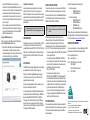
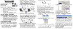
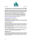
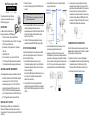
SPAN® Technology for OEMV QUICK START GUIDE GM-14915073 Rev 5 BOX CONTENTS In addition to this Quick Start Guide, the following is provided in your SPAN package: • 1 ProPak-V3 receiver and its Quick Start Guide • 1 IMU (see the IMU Type column in Table 1 of this guide) • 1 IMU to receiver interface cable • 2 serial cables (1 straight through and 1 null modem) • 1 I/O cable • 1 DB9 to USB cable • 2 12 V power cables (1 for receiver and 1 for IMU) • 1 CD containing PC Utilities and product documentation • 1 User Manual postcard for requesting printed manuals ADDITIONAL EQUIPMENT REQUIREMENTS The following additional equipment is needed for a basic setup: • 2. Insert the accompanying CD into the CD-ROM drive of the computer. May/2012 This guide provides the basic information you need to set up and begin using your SPAN Technology system. • • • • 1. Start up the computer. A Windows®-based PC with an RS-232 DB9 or USB port A power supply of +9 to +18 V DC (ProPak-V3) A separate power supply of +12 to +28 V DC for IMU A quality dual frequency GNSS antenna such as the GPS-702, or GPS-532 for airborne/high speed applications. For L-Band corrections use the GPS-702L antenna. A TNC to appropriate antenna connector RF cable INSTALLING THE PC UTILITIES Before setting up your SPAN system, install NovAtel’s PC Utilities on the Windows-based computer that you will use to communicate with it. This computer must have an RS-232 DB-9 or USB port. To access and download the most current version of our OEMV PC Utilities, go to the Support page of the NovAtel web site at www.novatel.com. 3. Connect COM1 of the receiver to a computer COM port using a null modem cable. UIMU-LN200 or UIMU-HG1700 IMU-FSAS 3. Select Install the OEMV PC Utilities from the window that is automatically displayed. If the window does not automatically open when the CD is inserted, select Run from the Start menu and select the Browse button to locate Setup.exe on the CD drive. 4. Install the PC Utilities by advancing through the steps provided in the NovAtel GPS PC Utilities setup program. SET UP YOUR SPAN HARDWARE Complete the following steps to set up and power your SPAN system. The example graphics show the connections on the back of the ProPak-V3 receiver. 1. Mount the IMU and antenna securely to a vehicle. For the simplest operation, align the Y-axis of the IMU with the forward axis (direction of travel) of the vehicle. Ensure the Z-axis is pointing up. Ensure that the GNSS antenna and IMU cannot move relative to each other. The distance and relative direction between them must be fixed. 2. Connect the IMU to the receiver using the IMU cable provided. The cable plugs into the ProPak-V3 port labelled AUX (for the IMU-FSAS, also plug its cable into the ProPak’s I/O port). 4. Connect the GNSS antenna to the antenna port on the receiver using an appropriate antenna cable. 5. Apply power to the IMU and then to the receiver. It is recommended that you place a back-up battery between the receiver and its voltage supply as a power buffer if installed in a vehicle. When a vehicle engine is started, power can dip to 9.6 V DC or cut-out to ancillary equipment causing the receiver and/or IMU to lose lock and calibration settings. 6. You may also have a user point device such as video equipment. Connect the device to the receiver’s I/O port using a cable that is compatible with both the receiver and the device. Refer to your device’s documentation for information on its connectors and cables. The arrow along the cable in the figure indicates a MARKIN pulse from the user device on the right to the ProPak-V3 I/O port (refer to the OEMV Family Firmware Reference Manual). COMMUNICATE WITH THE SPAN SYSTEM Serial or USB communication can be done using the NovAtel Connect software (installed with the PC Utilities) or a standard terminal program, such as Hyperterminal. To establish a connection to the receiver using Connect: 1. Launch Connect from the Start menu folder specified during the installation process. The default location is Start | All Programs | NovAtel PC Software | NovAtel Connect. 2. Select New Connection from the Device menu. 3. Enter a name for the Connection setup. 10. Select the new configuration from the Available Device Connections area of the Open Connection window. 11. Select the Open button to open SPAN receiver communications. Connect establishes a communication session with the receiver and displays the progress. Once connected, the progress box disappears and several windows open, including the Console window. Connect is now ready for use to view status information, enter commands or log data. USING NOVATEL CONNECT 4. Select Serial or USB from the Type list. 5. Select the computer port the SPAN receiver is connected to from the Port list. 6. If you selected Serial, select 115200 from the Baud Rate list. 7. If you selected Serial, ensure the Hardware Handshaking check box is cleared. Connect provides access to key information about your receiver and its position. The information is displayed in windows accessed from the View menu. For example, select Position Window from the View menu to display the position solution of the receiver. To show details of the GNSS and geostationary (SBAS) satellites being tracked, select the Tracking Status Window from the View menu. Select Help from the main menu for more details on Connect, its windows and features. 8. Click the OK button to save the new device settings. ENTERING COMMANDS The SPAN system uses a comprehensive command interface. Commands can be sent to the receiver using the Console window in Connect, which is opened from the View menu. Enter commands in the text box at the bottom of the Console window. The OEMV Family Quick Reference Guide, provided on the CD and available on the NovAtel website, provides comprehensive information about available commands. The SPAN Technology for OEMV User Manual provides information on a subset of these commands; in particular, the ones commonly used with SPAN. SAVECONFIG COMMAND If you change the configuration of a function and want to save the new settings for your next session, use the SAVECONFIG command. 9. From the Device menu select Open Connection. When using Connect to configure your receiver, ensure all of the graphical windows are closed before you issue the SAVECONFIG command. CONFIGURE THE SPAN SYSTEM DETERMINING WHEN THE POSITION IS VALID When the receiver has a valid position, the Solution Status field in the Connect Position window shows Computed: There are two methods to configure the SPAN system: • Configure SPAN Manually • Configure SPAN Using Connect Configure SPAN Manually Follow these steps to enable INS as part of the SPAN system using software commands: 1. Issue the INTERFACEMODE command to specify the receiver port connected to the IMU (see Table 1). 2. Issue the SETIMUTYPE command to specify the type of IMU (see Table 1). Table 1: Enable INS Commands IMU Type INTERFACEMODE SETIMUTYPE LN-200 comXa imu imu off imu_ln200 iIMU-FSAS comXa imarimu imarimu off imu_imar_fsasb HG1700 comX imu imu off imu_hg1700_ag11, or imu_hg1700_ag17, or imu_hg1700_ag58, or imu_hg1700_ag62 HG1900 comXa imu imu off imu_hg1900_ca29, or imu_hg1900_ca50 HG1930 comXa imu imu off imu_hg1930_aa99, or imu_hg1930_ca50 Landmark IMU comXa imu imu off imu_gladiator_landmark20 a a. Use the COM port number that the IMU is connected to. For example, OEMV-1DF requires COM1 but an OEMV-3 ProPak can use COM1 or COM3 for IMU communication. b. The iIMU-FSAS IMU uses RS-422 as its communication protocol. The OEMV-3 COM3 (can be labelled AUX on a ProPak-V3) supports either RS-232 or RS-422 as a factory configurable option. Basic configuration of the SPAN system is now complete. The inertial filter starts once the GNSS solution is solved and the IMU is connected. A GNSS antenna must be connected and tracking satellites for operation. 3. Enter the distance from the IMU to the GNSS antenna using the SETIMUTOANTOFFSET command. The offset between the antenna phase centre and the IMU axes must remain constant and be known accurately. The X (pitch), Y (roll) and Z (azimuth) directions are clearly marked on the IMU enclosure. The SETIMUTOANTOFFSET parameters are (where the standard deviation fields are optional): x_offset y_offset z_offset [x_stdev] [y_stdev] [z_stdev] A typical RTK GNSS solution is accurate to a few centimetres. For the integrated INS/GNSS system to have this level of accuracy, the offset must be measured to within a centimetre. Any offset error between the two systems shows up directly in the output position. For example, a 10 cm error in recording this offset will result in at least a 10 cm error in the output. If it is impossible to measure the IMU to GNSS antenna offset precisely, the offset can be estimated by carrying out the Lever Arm Calibration Routine. Refer to the SPAN for OEMV User Manual for details. Configure SPAN Using Connect Follow these steps to enable INS as part of the SPAN system using the NovAtel Connect software utility: 1. Select Wizards | SPAN Alignment from the Connect toolbar. This wizard takes you through the steps to complete a coarse or fast alignment, select the type of IMU and configure the receiver to IMU port to accept IMU data. Configuration for Alignment OPERATE THE SPAN SYSTEM A coarse alignment routine requires the vehicle to remain stationary for at least 1 minute. If that is not possible, an alternate, fast alignment routine is available. The fast or moving alignment is performed by estimating the attitude from the GPS velocity vector and injecting it into the SPAN filter as the initial system attitude. The system is ready to go once it is powered and the INS and GNSS are configured using the previously shown commands. Static coarse alignment is not available for the HG1930 or Landmark IMUs. Use the fast or moving alignment instead. CONFIGURE GNSS Depending on the accuracy of the solution required, the GNSS can be augmented with a number of correction sources including SBAS, L-Band and RTK (RTCA, RTCM, RTCM V3 and CMR). Refer to the OEMV Installation and Operation Manual / ProPak-V3 Quick Start, for SBAS, L-Band or RTK setup and operation. LOG SPAN DATA Raw GNSS, IMU and navigation data (position, velocity, attitude) are available from the system as ASCII or binary logs. Data can be collected through Connect using the Logging Control Window, or sent out the receiver COM port to usersupplied data collection software. For post-processing applications, collect the data shown in the Post-Process Data section of this guide. For real-time applications, the GNSS/INS solution is available through the logs listed in the SPAN Technology for OEMV User Manual including INSPOS, INSVEL, INSATT and INSPVA. These logs can be collected at rates up to the IMU data rate; however, there are some rate restrictions. Refer to the Data Collection section in the SPAN Operation chapter of the SPAN Technology for OEMV User Manual. Observe the status of the system in the Connect INS Window or in the status field of any of the INS solution logs (for example INSPOS, INSVEL, INSATT and INSPVA). INS data is available once there is a good GNSS solution. Therefore, an antenna must be connected for the system to function. If performing a static alignment, allow the system to be stationary for at least 1 minute after the GNSS solution is computed for its initial system alignment. If performing a kinematic alignment, move the vehicle forward at a speed faster than 1.15 m/s. The following status stages may be observed: • The status changes from INS_INACTIVE to INS_ALIGNING once the alignment starts. • The status changes to INS_ALIGNMENT_COMPLETE. when the alignment is complete. After some motion (stops, starts and turns), the attitude solution converges to within specifications, and the status changes to INS_SOLUTION_GOOD. • The status may occasionally change to INS_BAD_GPS_AGREEMENT. This status indicates that the inertial solution has detected poor quality GNSS positions from the receiver due to limited satellite visibility or high multipath conditions. The inertial filter may choose to disregard this information and wait for the GNSS quality to improve. The solution is still valid during these times, it is simply a warning flag that the GNSS/INS solution is more reliable than the GNSS-only solution. POST-PROCESS DATA Post-processing requires collection of simultaneous data from the base and rover stations. This includes accurate coordinates of the base station and accurate measurement of the IMU to antenna separation. Collect the following data for post-processing: • From the base station • RANGECMPB ontime 1 • RAWEPHEMB onnew • From the rover station(s) • RANGECMPB ontime 1 • RAWEPHEMB onnew • RAWIMUSB onnew • BESTLEVERARMB onnew SPAN system output is compatible with Inertial Explorer postprocessing software from the Waypoint Products Group, NovAtel Inc. Visit our website at www.novatel.com for details. QUESTIONS OR COMMENTS If you have any questions or comments regarding your SPAN system, please contact NovAtel Customer Service by: Email: [email protected] Web: www.novatel.com Phone: 1-800-NOVATEL (U.S. & Canada) 1-800-668-2835 1-403-295-4900 (International) Fax: 1-403-295-4901 NovAtel, SPAN, Inertial Explorer, Waypoint, ProPak and OEMV are registered trademarks of NovAtel Inc. Windows is a registered trademark of Microsoft Corporation. © Copyright 2012 NovAtel Inc. All rights reserved. Printed in Canada on recycled paper. Recyclable. Unpublished rights reserved under international copyright laws.