1
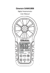
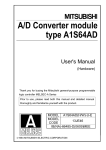
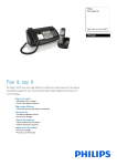
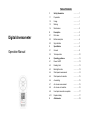
Table of Contents Digital Anemometer Operation Manual 1. Safety information ……………1 1.1 Preparation ……………1 1.2 Usage ……………1 1.3 Marking ……………1 1.4 Maintenance ……………2 2. Description ……………3 2.1 Part name ……………3 2.2 Button description ……………6 2.3 Sign definition ……………7 3. Specification ……………9 3.1 General ……………9 3.2 Technique data ……………10 4. Operating guidance ……………13 4.1 Power On/Off ……………13 4.2 Reading hold ……………13 4.3 Backlight function ……………13 4.4 Wind speed measurement ……………14 4.5 Wind speed unit selection ……………15 4.6 Area setting ……………15 4.7 Air volume measurement ……………15 4.8 Air volume unit selection ……………16 4.9 Use tripod connection receptacle ……………17 4.10 Replace battery ……………17 5. Attachments ……………18 Digital Anemometer Operation Manual Digital Anemometer Safety Information 1. Safety Information Please read carefully the following safety information before usage and maintain this anemometer while using it according to operating guidance, otherwise, the anemometer may be damaged. The anemometer will provide satisfactory services to you if you use and protect it appropriately. 1.1 Preparation 1.1.1 Please check for damage during transportation after receiving the anemometer. 1.1.2 If it should be stored and shipped under hard conditions, please confirm that whether the meter is damaged. 1.2 Usage 1.2.1 The meter should be used in the range of specified ambient temperature and humidity. 1.2.2 If you notice any abnormality or failure, it should stop using. 1.2.3 Don’t store or use the meter under the conditions of direct sunlight, high temperature and high humidity. 1.2.4 Don’t touch the fan blades with excessive force. 1.2.5 Don’t directly expose the blades in the hard light to avoid reading error. 1.3 Marking The mark indicates compliance with EMC requirements. -1- Operation Manual Safety Information Important Safety Information 1.4 Maintenance 1.4.1 Repair or maintenance should implemented by trained personnel. be 1.4.2 If there is dust on the fan blade, please blow it with clean air or scrub gently with a damp cloth and mild detergent. 1.4.3 Clean the meter with a damp cloth and mild detergent. Don’t use abrasive material or solvent. 1.4.4 The meter should be powered off when it is not in use. 1.4.5 The meter will consume small current, about ≤ 5μA, after shutdown. If the meter is not to be used for a long period, batteries should be removed to prevent damaging the meter. -2- Digital Anemometer Operation Manual Digital Anemometer Description Operation Manual Description 2. Description - This meter is a digital anemometer for measuring the ambient temperature, humidity, dew point temperature, wet bulb temperature, wind speed, and air volume. - This meter is a portable, professional measuring instrument with large-screen LCD and backlight, multi-unit switching functions. ⑻“ ”→ Backlight Button ⑼ Fan retaining bolt hole ⑽ Connection hole for fixing measurement bracket ⑾ Battery housing cover retaining bolt hole ⑿ Battery cover - This meter can be used for hand-held or fixed measurement. - This meter has the functions of reading hold, maximum, minimum, etc. - It has a low battery indicator and USB real time data uploading functions. 2.1 Part name ⑴ Fan ⑵ LCD ⑶“FUN” → Function switching button ⑷“ ”→ Power switch ⑸“UNIT” → Unit switching button ⑹ Maximum/Minimum button ⑺“HOLD” hold display -3- -4- Digital Anemometer Operation Manual Digital Anemometer Description Operation Manual Description 2.2 Button description Button: Switch for meter powering on/off. button Switch for turning on/off the backlight. HOLD button Hold display of LCD. FUN button It is used for switching among the functions of wind speed measurement, area setting and air volume measurement. Long press for three seconds to enable or disable "Auto Power-Off" function. MAX/MIN button Switch maximum/minimum/normal mode, long press to exit. UNIT button Switch unit, area (m², ft²), long press to switch (°C, °F) Wind speed (m/s, km/h, mil/h, ft/m, ft/s, knots), Air volume (CMS, CMM, CFM). -5- -6- Digital Anemometer Operation Manual Digital Anemometer Description 2.3 Sign definition HOLD Indicates Auto Power-Off status Reading hold state VEL Wind speed measurement state FLOW Air volume measurement state Operation Manual m/s Meters per second Km/h mil/h Kilometers per hour Nautical miles per hour Description Low battery indicator AREA Area setting required by air volume SLOW Indicates current wind-speed <5m/s FAST Indicates current wind-speed >5m/s MAX Displays maximum maximum/minimum mode after entering MIN Displays minimum after entering maximum/minimum mode m² Indicates that the current area setting unit is square meter ft² Indicates that the current area setting unit is square foot CMM Cubic meters per minute CMS CFM Cubic meters per second Cubic meters per minute knots ft/s ft/m -7- Nautical miles per hour, 1850 meters per hour Feet per second Feet per minute - 8 - Digital Anemometer Operation Manual Specification Temperature→ -20°C~80°C, no moisture condensation. 3.1.10 Storage environment: 3. Specification The meter should be recalibrated under the condition of 18°C~28°C, relative humidity <75% every year. Relative humidity→ 0~80%RH, no moisture condensation Temperature→ -10°C~50°C, no moisture condensation 3.1.11 Dimension: Meter →165LX85 WX38Hmm. 3.1.12 Weight: About 200g 3.1 General 3.1.1 Work height: Maximum 2000m 3.1.2 Work mode: Frequency of wind speed conversion 3.2 Technique data 3.1.3 Display: LCD Ambient temperature: 235°C, Relative humidity: <75% 3.1.4 Maximum show value: 9999 3.2.1 m/s Measuring range 3.1.5 Sampling time: About 0.4s/time. 3.1.6 Low battery indicator: LCD. 3.1.7 Work power: 1×9V 0.80 ~ 30.00 m/s 0.01 m/s 30.00 ~ 40.00 m/s Relative humidity→ 0~85%RH, no moisture condensation no ±(2.0% reading + 50 characters) 6F22 battery. 0°C~40°C, Accuracy on sign displays on 3.1.8 Operation environment: Temperature→ condensation Resoluti For reference only 3.2.2 km/h 1.40~108.00 km/h 0.01km/h ±(2.0% reading + 50 characters) moisture 108.0 ~ 144.0 km/h For reference only 3.1.9 Detector (fan) operation environment: Relative humidity→ 0~95%RH, no moisture condensation. -9- - 10 - 3.2.3 ft/s 1.30 ~ 98.50 ft/s 3.2.7 Air volume unit 0.01 ft/s 98.50 ~ 131.20 ft/s ±(2.0% reading + 50 CFM 0- 99990 (Area) 0 - 9.999 ft² characters) CMM 0- 99990 (Area) 0 - 9.999 m² For reference only CMS 0 - 9999 (Area) 0 - 9.999 m² 3.2.4 knots Measuring range Resoluti Accuracy on 0.80 ~ 58.30 knots 0.01 ±(2.0% reading + 50 knots characters) 58.30~77.70 knots For reference only 3.2.5 mile/h Measuring range Resoluti 0.90 ~ 67.20 0.01mile/ Accuracy on mile/h h ±(2.0% reading + 5 characters) 67.20~90.00 For reference only mile/h 3.2.6 ft/m Measuring range Resoluti Accuracy on 78 ~ 5900 ft/m 1ft/m ±(2.0% reading + 5 characters) 5900 ~ 7874 ft/m For reference only - 11 - 12 - Digital Anemometer Operation Manual Digital Anemometer Operating guidance 4. Operating guidance 4.1 Power On/Off Press the “ ” key to turn on or off the anemometer power. 4.2 Reading hold In the measurement process, if the reading should be kept, press "HOLD" key to lock the reading, and display the HOLD symbol; press it again to unlock. Note: In the reading hold state, “FUN”, “MAX/MIN” and “UNIT” keys are invalid. 4.3 Backlight In the measurement process, if the ambient light is too dark to read, you can press " " key to open the backlight. Backlight timer is set to 15 seconds. During this period, you can press " " key again to turn off backlight at any time. Note: The luminous body of backlight is LED with large operating current. Frequently using backlight will shorten battery life. Do not use backlight when unnecessary. - 13 - Operation Manual Operating guidance When the battery voltage ≤ 7V, the " " (low battery) symbol will show on the display. However, in the case of using the backlight, if the battery voltage ≥ 7V, the battery voltage drops because of its larger operating current, " " symbol may show (when " " symbol is showing, the accuracy of the measurement can’t be guaranteed). At this moment, you needn’t replace battery until the " " symbol display again under normal use condition without using backlight. 4.4 Wind speed measurement Place the detector (fan) into the test environment, "VEL" symbol will display on the screen, measurement is done with the fan surface perpendicularly to the wind direction. Note: 1. If the detector (fan) is not aiming at the wind direction, which will bring the measurement error. 2. For steady wind, the detector (fan) will get maximum reading when it is aiming at the wind direction. - 14 - Digital Anemometer Operation Manual Digital Anemometer Operating guidance 4.5 Wind speed measurement When using the meter to measure air volume, you can press “UNIT” key to select the measurement unit you required (m/s, km/h, mill/h, ft/m, ft/s, knots). 4.6 Area setting To measure air volume, you should first determine the area of air flue to be, area input steps are shown as following: ①.Press “FUN” key to make “AREA” display on the screen. ②.Use the “MAX/MIN” and “UNIT” keys to adjust value and unit, after adjusting area unit (m², ft²), then press “MAX/MIN” key. There should be an audible buzz, indicating that area input is completed and settings are saved. Operation Manual Operating guidance Measurement is done with the fan surface perpendicular to the wind direction. Note: 1. If the detector (fan) is not aligned in the wind direction, the measurement can be skewed. 2. For steady wind, the detector (fan) will get maximum reading when it is aiming at the wind direction. 4.8 Air volume unit selection When using the meter to measure air volume, you can press the “UNIT” key to select the measurement unit your required (CMS, CMM, CFM). ③.To change the area setting, please repeat the step ②. 4.7 Air volume measurement Place the detector (fan) into the test environment. Use the “FUN” key to set the meter to the Air volume measurement mode; the "FLOW" symbol should display on the screen. - 15 - - 16 - Digital Anemometer Operation Manual Digital Anemometer Operating guidance Operation Manual Attachments 4.9 Using tripod connection receptacle 4.9.1 When necessary, the meter can be fixed on a tripod. 4.9.2 When necessary, the meter can be used by hang. 5. Attachments ⑴ Battery ⑵ Detector 9V, NEDA 1604, 6F22 1pc 1pc Bracket ⑶ 4.10 Replacing battery Packaging 1pc Bag 4.10.1 If the “ ” sign appears, this indicates that the battery should be replaced. ⑷ 4.10.2 Power off the meter and remove the battery cover. (5) Operation 1pc Manual CD 1pc 4.10.3 Replace the old battery. 4.10.4 Install the battery cover properly. - 17 - - 18 – HYS006429