1
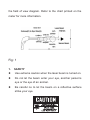
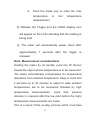
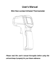
INFRARED THERMOMETER ATE-2523 User’s Manual www.tmatlantic.com OPERATION MANUAL INFRARED THERMOMETER Features: z Precise non-contact measurements z Built-in laser pointer z Automatic selection range and Resolution to 0.1|or 1| z ഒ/ഘ switchable button z Automatic Data Hold & Auto power off z The meter at 10 inches away measure 1 inch target z Backlit LCD display z MAX/MIN temperature measurement Function Wide range application: Food preparation, Safety and Fire inspectors, Plastic molding, Asphalt, Marine and screen printing, measure ink and dryer temperature, Diesel and Fleet maintenance. Field of View Meter’s field of view is 10:1, meaning that if the meter is 10 inches from the target, the diameter of the object under test must be at least 1 inch. Other distances are shown below in 1 the field of view diagram. Refer to the chart printed on the meter for more information. Fig: 1 1. SAFETY z Use extreme caution when the laser beam is turned on. z Do not let the beam enter your eye, another person’s eye or the eye of an animal. z Be careful no to let the beam on a reflective surface strike your eye. 2 2. z SPECIFICATIONS General specifications MEAS. RANGES -50.0ഒ to 760.0ഒ/-58.0ഘto 1400ഘ SAMPLE RATE Less than 1 second OVER LCD will show “OL”and”-OL” RANGE INDICATION POLARITY Automatic (no indication for positive polarity); Minus (-) sign for negative polarity. EMISSIVITY 0.95 fixed value FIELD OF VIEW D/S = Approx. 10:1 ratio (D = distance, S = spot) (Has 80% encircled energy at the focal point) DIODE LASER Output <1mW, Wavelength 630~670nm,class 2 (II) Laser product SPECTRAL 6~14um RESPONSE POWER OFF Automatic shut off after 7 seconds, approx. OPERATING 0ഒ to 50ഒ (32ഘto 122ഘ) TEMP. 3 STORAGE TEMP. -20oC to 60oC(-4oF to 140oF) RELATIVE 10%~90%RH operating, <80%RH storage HUMIDITY POWER SUPPLY 9V battery, NEDA 1604A or IEC 6LR61, or equivalent WEIGHT 180g. SIZE 82 x 41.5 x 160mm z Infrared thermometer specifications Range Resoluti Accuracy on o -50.0 C o 760.0 C to o -50.0 C o + 5 C; to o 0.1 C o -20.0 C o -20.0 C ± 2% of reading or ± to o 200.0 C 200.0 760 o .0o 2ºC; ± 2.5% of reading ± C to 2ºC C 4 Range Resoluti (Automatic selection 0.1 ഘ/ 1 on Accuracy ഘ) ഘ -58.0 to1400 ഘ -58.0 ഘ + 9 ഘ; to o -4.0 C ഘ 0.1ഘ -4.0ഘto 200.0 ± 2% of reading or + ഘ 4 ഘ; 200.0 ഘ to ± 2.5% of reading +4 999.9ഘ ഘ 1000 ഘ WR 1ഘ ഘ Note: Accuracy is given at 18 oC to 28 oC (64 oF to 82 oF), less than 80%RH. Field of View: Make sure that the target is larger than the unit’s spot size. The smaller the target, the closer you should be to it. When accuracy is critical, make sure the target is at least twice as large as the spot size. Emissivity: 5 0.95 fixed value 2 3. FRONTPANEL 1 ? 52 3 ¡ã C 200 400 800 ¡ãF DESCRIPTION + - 5 4 6 7 8 IR sensor 9 ཱ Laser pointer beam ི LCD Display ཱི Laser select key ུ Backlight select key ཱུ MODE select key ྲྀ C/F select key ཷ Measurement Trigger ླྀ Battery Cover ཹ Handle Grip 4. INDICATOR 6 Digital readout ཱ Temperature ഒ (Celsius) ིTemperatureഘ (Fahrenheit) ཱི Measuring indication ུ Data Hold ཱུ LOW battery indicator ྲྀ Laser Point ཷ Fixed emissivity (0.95) ླྀ MAX temperature measurement ཹ MIN temperature measurement ེ 5. MEASURMENT OPERATION 6. Hold the meter by its Handle Grip and point it 7 toward the surface to be measured. ཱ Pull and hold the Trigger to turn the meter on and begin testing. The display will light if the battery is good. Replace the battery if the display does not light. ི While measuring, the SCAN display icon will flicker in the upper left hand corner of the LCD. ཱི While continuing to pull the Trigger: a. Push the Laser button to turn on the laser pointer. When the laser is on the laser icon will appear on the LCD over the temperature. Aim the red beam approximately a half inch above the point of test (pressing the Laser button again turns the laser off). b. Select the temperature units (oC or oF) using the C/F buttons. c. Push the Backlight key to turn on the LCD backlighting function. 8 d. Push the mode key to enter the max temperature or min temperature measurement ུ Release the Trigger and the HOLD display icon will appear on the LCD indicating that the reading is being held. ཱུ The meter will automatically power down after approximately 7 seconds after the trigger is released. Note: Measurement considerations Holding the meter by its handle, point the IR Sensor toward the object whose temperature is to be measured. The meter automatically compensates for temperature deviations from ambient temperature. Keep in mind that it will take up to 30 minutes to adjust to wide ambient temperatures are to be measured followed by high temperature measurements, some time (several minutes) is required after the low (and before the high) temperature measurements are made. This is a result of the cooling process which must take 9 place for the IR sensor. 7. BATTERY REPLACEMENT As battery power is not sufficient, LCD will display “ ” replacement with one new battery type 9V is required. ཱ Open battery cover, then take out the battery from instrument and replace with a new 9-Volt battery and place the battery cover back. 10 7. NOTES: z How it Works Infrared thermometers measure the surface temperature of an object. The unit’s optics sense emitted , reflected, and transmitted energy, which is collected and focused onto a detector. The unit’s electronics translate the information into a temperature reading which is display on the unit. In units with a laser, the laser is used for aiming purposes only. z Field of View Make sure that the target is larger than the unit’s spot size. The smaller the target, the closer you should be to it. When accuracy is critical, make sure the target is at least twice as large as the spot size. z Distance & Spot Size As the distance (D) from the object increases, the spot size (S) of the area measured by the unit becomes larger. See: Fig: 1. z Locating a hot Spot To find a hot spot aim the thermometer outside the area of interest, then scan across with an up and down 11 motion until you locate hot spot. z Reminders Not recommended for use in measuring shiny or polished metal surfaces ( stainless steel, aluminum, etc.).See Emissivity ཱ The unit cannot measure through transparent surfaces such as glass. It will measure the surface temperature of the glass instead. ི Steam, dust, smoke, etc., can prevent accurate measurement by obstructing the unit’s optics. z Emissivity Most (90% of typical applications) organic materials and painted or oxidized surfaces have an emissivity of 0.95 (pre-set in the unit). Inaccurate readings will result from measuring shiny or polished metal surfaces. To compensate, cove the surface to be measured with masking tape or flat black paint. Allow time for the tape to reach the same temperature as the material 12 underneath it. Measure the temperature of the tape or painted surface. Emissivity Values Substance Thermal Substance emissivity Thermal emissivity Asphalt 0.90 to 0.98 Cloth (black) 0.98 Concrete 0.94 Human skin 0.98 Cement 0.96 Lather 0.75 to 0.80 Sand 0.90 Charcoal 0.96 (powder) Earth 0.92 to 0.96 Lacquer 0.80 to 0.95 Water 0.92 to 0.96 Lacquer (matt) 0.97 Ice 0.96 to 0.98 Rubber (black) 0.94 Snow 0.83 Plastic 0.85 to 0.95 Glass 0.90 to 0.95 Timber 0.90 Paper 0.70 to 0.94 Chromium 0.81 Ceramic Marble 0.90 to 0.94 0.94 oxides 13 Plaster 0.80 to 0.90 Copper oxides 0.78 Mortar 0.89 to 0.91 Iron oxides 0.78 to 0.82 Brick 0.93 to 0.96 Textiles 0.90 14