1
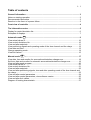
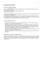
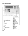
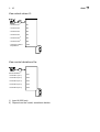
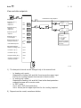
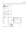
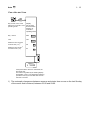
Flow-temperature controller
for heating / cooling
User's Manual, part 1
RDT 300 F001
7000927003 R4
About these operating instructions
Together with the RDT 300 controller for ventilation and air-conditioning, you receive two
documents:
Part 1 (7000927) of the Operating Instructions, which contains all the necessary information
on manual and automatic modes. This part is intended for the user.
Part 2 (7000928) of the Operating Instructions, which describes how to put the controller
into operation for the first time for specialists. This Part also contains further information for
project engineers and interested users.
The operating procedures have been described in this manual with the aid of illustrations.
When entering numerical values, all positions must be filled, including preceding noughts.
Example: 20.5 °C
Enter: 0205
In manual and automatic modes, incomplete entries are aborted automatically after two
minutes. The value that you have already entered will remain unchanged. Entries are accepted only if they are in the permissible range, or if they are restricted to that range.
The position requiring an input flashes in the display (user prompting) and it is marked by
an arrow in this manual .
Follow the various input stations, press the corresponding keys and observe the result on
the display.
1-1
Table of contents
General information .......................................................................................................... 3
Notes on starting operation ................................................................................................. 3
Recommended procedure................................................................................................... 3
Reaction in the event of a power failure.............................................................................. 3
Front view of controller .................................................................................................... 4
The information centre ..................................................................................................... 5
Display for control deviation Xw .......................................................................................... 6
Examples of displays .......................................................................................................... 7
Automatic mode
......................................................................................................... 9
View actual values Xi ........................................................................................................ 10
View control deviations Xw................................................................................................ 10
View and alter setpoints .................................................................................................... 11
View positioning signals and operating mode of the time channel and the relays ............ 12
View date and time............................................................................................................ 13
Change operating mode.................................................................................................... 14
View limit values................................................................................................................ 15
Manual mode
........................................................................................................ 17
View date, time and months for summertime/wintertime change-over.............................. 18
Set time, date and months for automatic summertime/wintertime change-over ............... 19
View and alter week program............................................................................................ 20
View actual values Xi ........................................................................................................ 21
View control deviations Xw................................................................................................ 21
View and alter setpoints .................................................................................................... 22
View and alter positioning signals; view and alter operating mode of the time channel and
the relays........................................................................................................................... 23
View and alter control parameters .................................................................................... 24
View and alter control parameters; view software version ................................................ 25
View and alter limit values................................................................................................. 26
Diagram of heating characteristic...................................................................................... 27
1-2
1-3
General information
Notes on starting operation
As soon as the RDT 300 controller for ventilation and air-conditioning has been switched
on, it is ready for operation.
Please make sure that the voltage supply is correct:
version F001 = 230 VAC
The stored factory settings (default settings) for the parameters on the control model permit
immediate control operations.
In order to make these instructions easier to understand, they are specially identified by a
grey background at the relevant points; these should be understood as examples, and they
are applicable to the normal operating mode of control model 0.
Recommended procedure
− Familiarise yourself with the controller's operating methods. Refer to the description of
the front view and the ‘information centre’.
− Depending on the technical remit (such as the flow diagram), enter the appropriate configuration values in the service level. The measured value inputs must also be coded
with the help of jumpers. All the other entries can be made from the keypad. In the service level, it is advisable to make the entries in the right order.
− Set the mode switch to ‘Automatic’. The controller will start with the default values for the
setpoints, P-band (proportional band) etc.
− Watch the installation; if necessary, match the parameters to the specific values for the
installation.
Reaction in the event of a power failure
All data and parameters are captive. In the event of a power failure, the continuous outputs
drop to 0 Volt, the relay outputs cut out and the display goes blank. When power has been
restored, the controller re-starts with the stored parameters. This also applies for lengthy
power failures.
1-4
Front view of controller
Flap holds instructions Memory (option) Mode switch
Manual mode
Automatic mode
Service level
Service and adjustment keys
0 ... 9
Numerical keys
PAR
Control parameters
SERV
Service
Cl Clear
User keys with
function keys
Xs Setpoint
Xi Actual value
XW Control deviation
Y Positioning signal
I
Input
L
Limit
Date and time
PRO
Weekly programme
SET
Time, date...
Information centre
Forwards
Backwards and
minus sign
B09791
1-5
The information centre
Day code
Enter value with preceding mathematical sign and unit, and time
Parameters
View control offset Xw
Control action, min. or max. limitation,
open/close/on command
for switching outputs
Operating modes:- Control (Automatic)
- Manual
Service level
Enter control parameters
B09792a
1-6
Display for control deviation Xw
Definition:
Control deviation = actual value – setpoint
Xw = Xi – Xs
B06970
Positive control deviation
<
1,5
1,0
0,2
50
1)
Control deviation Xw
>
1,5
1,0
0,2
50
3,0
2,0
0,4
100
7,5 15,0
5,0 10,0
1,0 2,0
250 500
Negative control deviation
Unit of meas.
°C
%, % r.H., kJ/kg
g/kg
- 1)
Control deviation Xw
<
<
-1,5
-1,0
-0,2
-50
-1,5
-1,0
-0,2
-50
-3,0
-2,0
-0,4
-100
Free unit of measurement: with respect to displayed range 0...4999.
-7,5 -15,0
-5,0 -10,0
-1,0 -2,0
-250 -500
B06971a
1-7
Examples of displays
− automatic mode
− actual value Xi3 with unit of
measurement
− Xw display
B06975
−
−
−
−
Manual mode
Input for control parameters
Reset time for controller 1
View Xw
B06976
− Service level
− Upper setpoint limit 50.0 °C
SERV
B06977a
− Service level
− Minimum limitation Y2
ready for the input of the first
position
SERV
B06978a
1-8
Auto
Automatic mode
Control based on the setpoint
1-9
1 - 10
Auto
View actual values Xi
Xi
- Actual value 1
Xi1
- Actual value 2
Xi2
- Actual value 3
Xi3
- Actual value 4
Xi4
- Actual value 5
1)
1)
Xi5
- Actual value 6
Xi6
- Averaged outdoor
temperature
nXi3
B09354
View control deviations Xw
Xw
2)
Control deviation
- Controller 1 (PI 1)
Xw1
- Controller 2 (PI 2)
Xw2
- Controller 3 (PI 3)
Xw3
- Controller 4 (PI 4)
Xw4
- Controller 5 (PI 5)
Xw5
B09355a
1) Input Ni1000 only.
2) Depends on the model, sometimes hidden.
Auto
1 - 11
View and alter setpoints
Xs
Press button to alter setpoint
Setpoint for:
I
Controller 1 (PI 1)
- Setpoint 1
- Setpoint 2
Xs1
Xs2
Controller 2 (PI 2)
- Setpoint 1
- Setpoint 2
Xs3
Xs4
16,0°C
19,0°C
Controller 5 (PI 5)
- Setpoint
Xs5
0,0°C
Controller 1 (PI 1)
- Frost setpoint
XsF
5,0°C
Input
Xs. +... 1)
20,0°C
16,0°C
I
Xs
Input
Xs. - ... 1)
2)
Dewpoint limiter (PI 4)
- Dewpoint interval 1)
TP1
- Calculated dewpoint
TP1
Calculated setpoints
- Based on heating curve
SoLL
- Controller 1 (PI 1)
cXs1
- Controller 2 (PI 2)
cXs3
- Dewpoint limiter (PI 4)
cXs4
- Auxiliary controller for
cascade controller
cXs
0,0°C
1)
+/ - 0,1°C
+/ - 1 %, %r.H.
+/ - 0,1 g/kg
+/- 1 kJ/kg
Free unit of measurement, dependent
on range
B09356b
1) The dew-point interval can be changed only in the manual level.
–
–
–
In ‘heating only’ mode:
Setpoints for cooling, Xs3 and Xs4, fixed as per the upper input
limit for the ‘cooling’ setpoint that was set in service mode.
In ‘cooling only’ mode:
Setpoints for heating, Xs1 and Xs2, fixed at the frost-protection
setpoint that was set in service mode.
In ‘OFF’ mode:
Xs1 = Xs2 = XsF (frost protection)
Xs3 = Xs4 as per the upper input limit for the ‘cooling’ setpoint.
2) Depends on the model, sometimes hidden.
1 - 12
Auto
View positioning signals and operating mode of the time channel and the relays
Y
Positioning signal Y1
Y1
Positioning signal Y2
Y2
Output variable Y3
Y3
Calcul. positioning signals
- Controller 1 (PI 1)
1)
Yc1
- Controller 2 (PI 2)
Yc2
- Controller 3 (PI 3, auxiliary
controller for cascade)
Yc3
- Controller 4, limiter (PI 4)
Yc4
- Controller 5 (PI 5)
Yc5
Operating mode
- Time channel To
T0
- Relay 1
rEL1
- Relay 2
rEL 2
- Relay 3
rEL 3
- Relay 4
rEL 4
- Relay 5
rEL 5
- Relay 6
rEL 6
Display:
= Manual, continuously On
for T0
= Manual, continuously Off
= Automatic (weekly program)
= On
Rel. 1...6
= Off
B09357b
1) Depends on the model, sometimes hidden.
Auto
1 - 13
View date and time
Day of week, time, active
setpoint for controller 1 and
operating mode
Display:
Day of week,
time and active
setpoint for
controller 1,
operating mode
Day + month
date
Year
Yea
Switchover from summer
to winter time (-1h) 1)
Wi
10
Switchover from winter 1)
to summer time (+1h)
So
3
Flashing:
3
12:00
B09359a
If the power failure reserve is exhausted, the
time will be lost.
This status is signalled by the flashing display:
"Wednesday 12:00". Time-dependent switching
operations will only be executed after the time
has been corrected.
1) The automatic changeover between summer and winter time occurs on the last Sunday
of the month that is entered, between 02:00 and 03:00.
1 - 14
Auto
Change operating mode
Display:
Day of week,
time and active
setpoint for
controller 1
Alter operating mode
---
l
Input
l
- Heating and cooling
- Heating only
- Cooling only
- Off mode with frost
monitoring
B09360
Auto
1 - 15
View limit values
L
Limit value 1
- Switching point
L1
- Delay
Lv1
- Follow-up
Ln1
Limit value 2
- Switching point
L2
- Delay
Lv2
- Follow-up
Ln2
Limit value 3
- Switching point
L3
- Delay
Lv3
- Follow-up
Ln3
Limit value 4
- Switching point
L4
- Delay
Lv4
- Follow-up
Ln4
Changeover
- Switching point
Co
- Delay
Cov
- Follow-up
Con
B09361a
Functions and values vary according to the model, so some might not be shown.
1 - 16
Auto
Manual
Manual mode
In this mode, you can:– set the positioning signals between 0...100 %
– alter the setpoints, and
– set the control parameters
1 - 17
1 - 18
Manual
View date, time and months for summertime/wintertime change-over
Day of week, time, active
setpoint for controller 1
and operating mode
Display:
Day of week,
time and active
setpoint for
controller 1,
operating mode
Day + month
date
Year
Yea
Switchover from summer
to winter time (-1h) 1)
Wi
10
Switchover from winter
to summer time (+1h) 1)
So
3
Flashing:
3
12:00
B09363a
If the power failure reserve is exhausted, the time will be lost.
This status is signalled by the flashing display:
"Wednesday 12:00". Time-dependent switching operations
will only be executed after the time has been corrected.
1) The automatic changeover between summer and winter time occurs on the last Sunday
of the month that is entered, between 02:00 and 03:00.
Manual
1 - 19
Set time, date and months for automatic summertime/wintertime change-over
SET
8
Enter time
Input
:
Cl
Day of week, time, active
setpoint for controller 1 and
operating mode
00:00...23:59
Enter time and month
Day + month
date
Year
Yea
Cl
:
Input
Date
Day: 01...31
Month: 01...12
Enter year
Cl
:
Input
Year
1999...
Switchover from summer to
Wi
winter time (-1h) 1)
10
Switchover from winter to
summer time (+1h) 1)
3
So
l
Flashing:
3 12:00
If the power failure reserve is exhausted,
the time will be lost.
This status is signalled by the flashing
display: "Wednesday 12:00".
Time-dependent switching operations
will only be executed after the time has
been corrected.
Input
1, 2
3, 4
5, 6
7, 8
9, 10
11, 12
l
January, February
March, April
May, June
July, August
September, October
November, December
B09362a
1) The automatic changeover between summer and winter time occurs on the last Sunday
of the month that is entered, between 02:00 and 03:00.
To deactivate the changeover from summer to winter time, enter identical months such
as WiSo = 3 and SoWi = 3.
1 - 20
Manual
View and alter week program
PRO
2)
32 Memory Addresses
Setpoint switchover for:
- Controller 1 (PI 1)
- Controller 2 (PI 2)
Xs1
Xs3
0 06:00
0 06:00
- Controller 1 (PI 1)
- Controller 2 (PI 2)
Xs2
Xs4
0 22:00
0 22:00
T0
0 06:00
T0
0 22:00
- Time channel T0
1)
Delete displayed
switching time
Cl
- --:--
!
l
Input
- --:--
- --:--
Note sequence!
Xs1...4 Setpoints 1...4
Time channel
- On
T0
- Off
T0
Day of week an time
B09364a
Day of the week:
1 = Monday
2 = Tuesday
3 = Wednesday
4 = Thursday
5 = Friday
6 = Saturday
7 = Sunday
0 = daily
The daily switching commands (0__:__) are not executed on special days, e.g. 7__:__).
If all the switching times are deleted, or if the time is lost (power failure reserve is
exhausted) control operation will use setpoints Xs1 and Xs3.
1) Is shown only if at least one additional switching command is entered.
2) The fill level of the tank is indicated on the bar chart for the control offset.
Manual
1 - 21
View actual values Xi
Xi
- Actual value 1
Xi1
- Actual value 2
Xi2
- Actual value 3
Xi3
- Actual value 4
Xi4
- Actual value 5 1)
Xi5
- Actual value 6 1)
Xi6
- Averaged outdoor
temperature
nXi3
B09365
View control deviations Xw
Xw
Control deviation 2)
- Controller 1 (PI 1)
Xw1
- Controller 2 (PI 2)
Xw2
- Controller 3 (PI 3)
Xw3
- Controller 4 (PI 4)
Xw4
- Controller 5 (PI 5)
Xw5
B09366a
1) Inputs for Ni1000 only; display ...°C.
2) Depends on the model, sometimes hidden.
1 - 22
Manual
View and alter setpoints
Xs
Setpoint for
Input
Cl
Controller 1 (PI 1)
- Setpoint 1
- Setpoint 2
Xs1
Xs2
20,0°C
16,0°C
Controller 2 (PI 2)
- Setpoint 1
- Setpoint 2
Xs3
Xs4
16,0°C
19,0°C
Controller 5 (PI 5)
- Setpoint
Xs5
0,0°C
Controller 1 (PI 1)
- Frost setpoint
XsF
5,0°C
Dewpoint limiter (PI 4)
- Dewpoint interval
TP1
- Calculated dewpoint
TP1
Calculated setpoints
- Based on heating curve
SoLL
- Controller 1 (PI 1)
cXs1
- Controller 2 (PI 2)
cXs3
- Dewpoint limiter (PI 4)
cXs4
- Auxiliary controller for
cascade controller
cXs
_ Xs_
Values apply for heating
and cooling modes
-30,0...150,0°C
0,0...100,0 %,%r.H.
0,0...20,0g/kg
0,0...100kJ/kg
-4999...+4999
0,0°C
B09367b
–
–
–
In ‘heating only’ mode:
Setpoints for cooling, Xs3 and Xs4, fixed as per the upper input
limit for the ‘cooling’ setpoint that was set in service mode.
In ‘cooling only’ mode:
Setpoints for heating, Xs1 and Xs2, fixed at the frost-protection
setpoint that was set in service mode.
In ‘OFF’ mode:
Xs1 = Xs2 = XsF (frost protection)
Xs3 = Xs4 as per the upper input limit for the ‘cooling’ setpoint.
Manual
1 - 23
View and alter positioning signals; view and alter operating mode
of the time channel and the relays
Y
Positioning signal Y1
Y1
Positioning signal Y2
Y2
Output variable Y3
Y3
I
Input
_ Y_
0...100%
1)
Calcul. positioning signals
- Controller 1 (PI 1)
Yc1
- Controller 2 (PI 2)
Yc2
- Controller 3 (PI 3, auxil.
controller for cascade)
Yc3
- Controller 4,
limiter (PI 4)
Yc4
- Controller 5 (PI 5)
Yc5
Operating mode
- Time channel To
T0
- Relay 1
rEL1
Input
l
l
- Relay 2
rEL 2
- Relay 3
rEL 3
Operating mode:
- Relay 4
rEL 4
Automatic (weekly program)
- Relay 5
rEL 5
- Relay 6
rEL 6
2)
T0
Manual, continuously On
Manual, continuously Off
B09368a
1) Depends on the model, sometimes hidden.
2) Setting for T0 is adopted in automatic mode.
Relay
1 - 24
Manual
View and alter control parameters
PAR
6
Input
Controller 1 (PI 1)
- Proportional band
Xp1
10,0°C
- Reset time
Tn1
180 s
Controller 2 (PI 2)
- Proportional band
Xp2
10,0°C
- Reset time
Tn2
180 s
Auxil. contr. 3 (PI 3, cascade)
- Proportional band
Xp3
10,0°C
- Reset time
Tn3
180 s
Controller 4 (PI 4)
- Proportional band
Xp4
10,0°C
- Reset time
Tn4
180 s
Controller 5 (PI 5)
- Proportional band
Xp5
10,0°C
- Reset time
Tn5
0s
Auxil. contr. 3 (PI3, cascade)
- Lower setpoint limit
rXsc
14,0°C
- Upper setpoint limit
rXsc
20,0°C
Command module 1
- Start of shift
1FP
32,0°C
- End of shift
1F1
22,0°C
- Amount of shift
1 Ws
3,0°C
Command module 2
- Start of shift
2FP
20,0°C
- End of shift
2F1
-15,0°C
- Amount of shift
2 Ws
Heating curve 1)
SL
0,6
Period of time for averaged
outdoor temperature
Tl
12
Cl
Xp.:
0,1...250,0°C
0,1...200,0 %
0,1...100,0%r.H.
0,1...20,0g/kg
0,1...100kJ/kg
1...4999
Tn:
0...9990s
Cl
Input
.FP, .F1:
-30,0...150,0°C
0,0...200,0 %
0,0...100,0%r.H.
0,0...20,0g/kg
0,0...100kJ/kg
-4999...+4999
Ws.:
0,0...150,0°C
0,0...200,0°C
0,0...100,0%r.H.
0,0...g/kg
0,0...100,0kJ/kg
SL: 0,1...5,0
20,0°C
Input
Cl
0...72 h
B09369b
Value depend depends on the model, sometimes hidden.
1) Diagram of heating characteristic: see page 27.
Manual
1 - 25
View and alter control parameters; view software version
Dry flooring function
- Starting temperature
ST
15,0
- Final temperature
End
25,0
- Increase per day
Er
5,0
Cl
Input
ST:
10,0...40,0°C
Final:
25,0...60,0°C
Changeover mode 2:
- Release value for heating
- Differential value
(hysteresis) for cooling
FH
22,0
HK
1,0
Increase:
1,0... 10,0°C
Input
Cl
-30,0...150,0°C
0,0...200,0 %
0,0...100,0%r.H.
0,0...20,0g/kg
0,0...100kJ/kg
-4999...+4999
- Mininum operating period
(in days)
MT
3
- Time of interrogation
CT
02:00
Cl
Input
MT: 0...9 days
CT:
00:00...23:59
Software version
VER
Device type
R-
300
B09370a
Floor-drying function:
When this function has been activated in service mode, heating begins with the setpoint
entered at ST (starting temperature).
In the following night at 02.00 hrs, the setpoint is raised by the value set using Er.
This daily increase is carried out as long as the end temperature that was set using End
has been reached. The floor-drying function is then concluded.
1 - 26
Manual
View and alter limit values
L
Enter switching point
Limit value 1
- Switching point
L1
5,0 %
- Delay
Lv1
0s
- Follow-up
Ln1
180 s
Limit value 2
- Switching point
L2
5,0 %
- Delay
Lv2
0s
- Follow-up
Ln2
180 s
Limit value 3
- Switching point
L3
22 °C
- Delay
Lv3
2s
- Follow-up
Ln3
0s
Limit value 4
- Switching point
L4
- Delay
Lv4
- Follow-up
Ln4
Changeover
- Switching point
Co
23,0°C
- Delay
Cov
2s
- Follow-up
Con
0s
Cl
Input
L_
-30,0...150,0°C
Xw: 0,0...180,0 °C
0,0...100,0 %,%r.H.
0,0...20,0g/kg
0,0...100kJ/kg
-4999...+4999
Enter time
Cl
Input
L_
0...9999s
By default inactive = OFF
Mode 1
B09371c
Manual
1 - 27
Diagram of heating characteristic
The heating characteristic determines the setpoint of the secondary supply temperature as
a function of the outside temperature. The heating characteristic is determined in the main
by the base point TI
(= XS1) and the slope.
Slope
2,5
3,0
3,5 4,0
2,0
100
1,8
90
1,6
70
1,2
1,0
60
0,8
50
0,6
Flow temp.
80
1,4
Slope
[°C]
40
0,4
30
-20
-15
-10
[°C]
-5
0
Outside temp.
5
10
-10
15
-5
]
°C
TI [
5
B01916
Spread of heating characteristics for TI = 20 °C and curvature factor = 0.5
The following applies: small heating surfaces require higher supply temperatures and large
heating surfaces require lower supply temperatures in order to be able to provide a certain
heating output.
Recommended values for slopes:
Hot-water radiator heating
Low-temperature heating
Underfloor heating
1.4
1.0
0.6
After the base point or the slope has been amended, the building (and possibly the heating
system) needs time to adapt itself to the new value. For this reason, no more than one adjustment per day should be made.
1 - 28
Manual