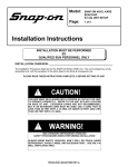
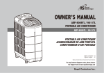
1
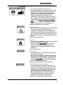
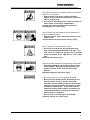
USERS MANUAL Kool Kare Snap-on Tools Company Limited One (1) Year Warranty Snap-on Tools Company (the “Seller”) warrants only to the original purchaser that under normal use, care and service, the Equipment (except as otherwise provided herein) shall be free from defects in material and workmanship for one year from the date of original invoice. Items such as leads, probes, external hoses, adapters and all other attachments, supplies and consumables (except as otherwise provided herein) are warranted for 90 calendar days from the date of original invoice. Filter elements are not warranted. SELLER’S OBLIGATIONS UNDER THIS WARRANTY ARE LIMITED SOLELY TO THE REPAIR OR, AT SELLER’S OPTION, REPLACEMENT OF EQUIPMENT OR PARTS WHICH TO SELLER’S SATISFACTION ARE DETERMINED TO BE DEFECTIVE AND WHICH ARE NECESSARY, IN SELLER’S JUDGMENT, TO RETURN THIS EQUIPMENT TO GOOD OPERATING CONDITION. NO OTHER WARRANTIES, EXPRESS OR IMPLIED OR STATUTORY, INCLUDING WITHOUT LIMITATION ANY IMPLIED WARRANTY OF MERCHANTABILITY OR FITNESS FOR A PARTICULAR PURPOSE, SHALL APPLY AND ALL SUCH WARRANTIES ARE HEREBY EXPRESSLY DISCLAIMED. This warranty does not cover (and separate charges for parts, labor and related expenses shall apply to) any damage to, malfunctioning, inoperability or improper operation of the Equipment caused by, resulting from or attributable to (A) abuse, misuse or tampering; (B) alteration, modification or adjustment of the Equipment by other than Seller’s authorized representatives; (C) installation, repair or maintenance (other than specified operator maintenance) of the Equipment or related equipment, attachments, peripherals or optional features by other than Seller’s authorized representatives; (D) improper or negligent use, application, operation, care, cleaning, storage or handling; (E) fire, water, wind, lightning or other natural causes; (F) adverse environmental conditions, including, without limitation, excessive heat, moisture, corrosive elements, or dust or other air contaminants, radio frequency interference, electric power failure power line voltages beyond those specified for the Equipment, unusual physical, electrical or electromagnetic stress and/or any other condition outside of Seller’s environmental specifications; (G) use of the Equipment in combination or connection with other equipment, attachments, supplies or consumables not manufactured or supplied by Seller; or (H) failure to comply with any applicable federal, state or local regulation, requirement or specification governing emission analyzers and related supplies or consumables. Repairs or replacements qualifying under this Warranty will be performed on regular business days during Seller's normal working hours within a reasonable time following purchaser's request. All requests for Warranty service must be made during the stated warranty period. This Warranty is nontransferable. Snap-on Tools Company Kenosha, Wisconsin 53141-1410 Part Number ZEEAC304D Revision A ©1999 SNAP-ON INCORPORATED Printed in U.S.A. Safety Information Safety Notice For your safety, read this manual thoroughly before operating your KOOL KARE unit. Your KOOL KARE unit is intended for use by properly trained, skilled professional automotive technicians. The safety messages presented below and throughout this user's manual are reminders to the operator to exercise care when using this unit. There are many variations in procedures, techniques, tools, and parts for servicing vehicles, as well as in the skill of the individual doing the work. Because of the vast number of test applications and variations in the products that can be tested with this instrument, Snap-on cannot possibly anticipate or provide advice or safety messages to cover every situation. It is the automotive technicians responsibility to be knowledgeable of the system that is to be tested. It is essential to use proper service methods and test procedures and to perform tests in an appropriate and acceptable manner that does not endanger your safety, the safety of others in the work area, or the vehicle or equipment being tested. It is assumed that the operator has a thorough understanding of vehicle air conditioning systems before using this KOOL KARE unit. This understanding of principles and operating theories is necessary for competent, safe and accurate use of this instrument. Before using your KOOL KARE unit, always refer to and follow the safety messages and applicable test procedures provided by the manufacturer of the vehicle or equipment being tested. Read All Instructions Read, understand and follow all safety messages and instructions in this manual and on the test equipment. Safety messages in this section of the manual contain a signal word with a three-part message and, in some instances, an icon. I Safety Information The signal word indicates the level of the hazard in a situation. • DANGER indicates an imminently hazardous situation which, if not avoided, will result in death or serious injury to the operator or bystanders. • WARNING indicates a potentially hazardous situation which, if not avoided, could result in death or serious injury to the operator or bystanders. • CAUTION indicates a potentially hazardous situation which, if not avoided, may result in moderate or minor injury to the operator or bystanders. • IMPORTANT indicates a situation which, if not avoided, may result in damage to the test equipment or vehicle. Safety messages in this section contain three different type styles. • Normal type states the hazard. • Bold type states how to avoid the hazard. • Italic type states the possible consequences of not avoiding the hazard. An icon, when present, gives a graphical description of the potential hazard. IMPORTANT SAFETY INSTRUCTIONS Power Risk of a lack of oxygen. — Vehicle exhaust gases contain carbon monoxide. — Refrigerant gas can displace air in work area. Use your KOOL KARE unit in locations with mechanical ventilation providing at least four air changes per hour. Impairment of breathing can cause injury. Risk of electric shock and fire. To avoid electric shock the power cord must be connected to a properly grounded A.C. outlet. Do not remove or bypass the grounding pin. Use the proper A.C. outlet for the unit to operate correctly. See the ID plate on the back of the unit. Extension cords are not recommended. If an extension cord must be used, use: 16 AWG for cords up to 50', and 14 AWG for cords greater than 50' but less than 100'. Do not use on wet surfaces or expose to rain Use only fuses with the rating specified near the fuse holder. Electric shock and fire can cause injury. II Safety Information Refrigerant Risk of expelling refrigerant under pressure. Wear safety goggles and protective gloves, user and bystander. Everyday eyeglasses only have impact resistant lenses, they are NOT safety glasses. If any refrigerant gets into the eyes, flush with water and seek a doctor's aid immediately, even though irritation may cease. Do not remove master filter while under pressure. Perform maintenance procedure for removing master filter in Chapter 3Changing the Master Filter . Prevent refrigerant from contacting the skin. Expelled refrigerate can cause injury. Risk of explosion. Do not use compressed shop air for leak detection or to pressure test a system containing refrigerant. Refrigerant can form combustible mixtures at pressures above atmospheric and with air concentrations greater than 60% by volume. Do not heat a container of refrigerant above 125°F (52°C). Explosion can cause injury. Risk of fire. Do not use this equipment in the vicinity of spilled or opened containers of gasoline. Do not use your KOOL KARE unit or any leak detector equipment if R-12 substitutes are suspected. R-12 refrigerant substitutes may be flammable. Fire can cause injury. Risk of poison. Avoid breathing air conditioning refrigerant and lubricant vapor or mist. Do not allow refrigerant to contact open flame or be drawn into a running engine. This can cause refrigerant to become poisonous phosgene gas. Use your KOOL KARE unit to remove refrigerant from air conditioning systems. Exposure can irritate eyes, nose and throat. Risk of irritation to mucous membranes. Avoid breathing A/C refrigerant and lubricant vapor or mist. Exposure may irritate eyes, nose and throat. To remove HFC-134a from the A/C system, use service equipment certified to meet the requirements of SAE J2210 (HFC-134a Recycling Equipment). Additional health and safety information may be obtained from the refrigerant and lubricant manufacturers. Exposure can irritate eyes, nose and throat. III Safety Information Oil (Lubricant) Risk of expelling oil under pressure. Wear safety goggles and protective gloves, user and bystander. Everyday eyeglasses only have impact resistant lenses, they are NOT safety glasses. If any oil gets into the eyes, flush with water and seek a doctor's aid immediately, even though irritation may cease. Expelled oil can cause injury. Oil Separator Bowl Risk of expelling refrigerant under pressure. Wear safety goggles, user and bystander. Everyday eyeglasses only have impact resistant lenses, they are NOT safety glasses. Never open the metal oil separator bowl when it is under pressure. Service should be performed by a certified A/C service technician. Remove bowl by performing maintenance procedure in Chapter 3Metal Oil Separator Bowl in this manual. Remove bowl only when the light is on continuously and no refrigerant is present. Loosen the metal oil separator bowl vacuum release thumbscrew only when the light is on continuously and no refrigerant is present. Expelled refrigerant can cause injury. General Engine systems can malfunction expelling fuel, oil vapors, hot steam, hot toxic exhaust gases, acid, refrigerant and other debris. Wear safety goggles and protective gloves, user and bystander. Everyday eyeglasses only have impact resistant lenses, they are NOT safety glasses. Service should be performed by a certified A/C service technician. Engine systems that malfunction can cause injury. IV Safety Information The engine compartment contains electrical connections and hot or moving parts. Keep yourself, test leads, clothing and other objects clear of electrical connections and hot or moving engine parts. Do not place test equipment or tools on fenders or other places in the engine compartment. Contact with electrical connections and hot or moving parts can cause injury. Service hoses can not withstand high temperatures or severe mechanical stress. Keep the service hoses away from moving or hot engine parts. Service hoses can split or burst causing injury. Risk of explosion if improper tank is used. Do not use any tank with this equipment other than part number EAA0158C00A for R-134a. This tank is D.O.T. certified for refilling. D.O.T certified tanks are marked "D.O.T. 4BA 350" or "D.O.T. 4BA 400". Explosion can cause injury. Removing tubing assemblies may discharge refrigerant. Wear safety goggles and protective gloves, user and bystander. Everyday eyeglasses only have impact resistant lenses, they are NOT safety glasses. Expelled refrigerant may cause injury. A test vehicle may move if not properly prepared. Block the drive wheels before performing a test with the engine running. Unless instructed otherwise, set the parking brake and put the gear selector in neutral (manual transmission) or park (automatic transmission). If the vehicle has an automatic parking brake release, disconnect the release mechanism for testing and reconnect it when testing is completed. Do not leave a running engine unattended. A moving vehicle can cause injury. V Safety Information Risk of injury. This equipment should be operated by qualified personnel only. Use this equipment only as described in this manual. Use only the manufacturers recommended attachments. Do not operate equipment with a damaged cord or if the equipment has been dropped or damaged, until it has been examined by a qualified service representative. Care should be taken to arrange the power cord so that it will not be tripped over or pulled. Always unplug equipment from electrical outlet when not in use. Never use the cord to pull the plug from the outlet. Grasp the plug and pull to disconnect. Let the equipment cool completely before putting it away. Loop the power cord loosely in proper location when storing. Operation of your KOOL KARE unit by anyone other than qualified personnel may result in injury. Risk of refrigerant leakage. Hose couplings are not self closing. Always close the valves on the gauge set before disconnecting a hose. Loosened hose couplings can leak refrigerant into the atmosphere. Misdiagnosis may lead to incorrect or improper repair and/or adjustment. Do not rely on erratic, questionable, or obviously erroneous test information or results. If test information or results are erratic, questionable, or obviously erroneous, make sure that all connections are correct and that the test procedure was performed correctly. Refer also to the Maintenance/Troubleshooting section and perform tests and make repairs as required. If test information or results are still suspicious, do not use them for diagnosis. Contact your Snap-on Representative. Improper repair and/or adjustment may cause vehicle or equipment damage or unsafe operation. SAVE THESE INSTRUCTIONS VI Table of Contents Safety ........................................................................................................................................................ I Introduction ........................................................................................................................................ 1-1 Refrigerant Gases .................................................................................................................... 1-2 Refrigerant Handling .................................................................................................... 1-3 Refrigerant Safety ...................................................................................................... 1-3 Refrigerant Substitute Warning .................................................................................... 1-4 Refrigerant Oils .......................................................................................................... 1-5 Refrigerant Oil Safety .................................................................................................. 1-5 Functional Description .............................................................................................................. 1-6 Front View .................................................................................................................. 1-6 Back View .................................................................................................................. 1-8 R-134a Accessories .................................................................................................... 1-9 Particle Filter Assembly ............................................................................................ 1-10 Specifications .......................................................................................................................... 1-10 General .................................................................................................................... 1-10 Operating .................................................................................................................. 1-10 Storage .................................................................................................................... 1-11 Capacities ................................................................................................................ 1-11 Language Selection ................................................................................................................ 1-12 Installation and Operation .......................................................................................................... 2-1 Component Identification ............................................................................................ 2-1 Installation ................................................................................................................................ 2-1 Preparing and Installing Recovery Tank ...................................................................... 2-1 Adding Refrigerant to Kool Kare ................................................................................ 2-4 Operation .................................................................................................................................. 2-6 Preliminary Checks ...................................................................................................... 2-7 Connecting Service Hoses To Vehicle ........................................................................ 2-8 Full Sequence Program .............................................................................................. 2-9 Recycle Only Program ........................................................................................ 2-10 Vacuum Only Program ........................................................................................ 2-11 Charge Only Program .......................................................................................... 2-12 Displaying Refrigerant Amount .................................................................................. 2-13 Removing Recovery Tank .......................................................................................... 2-14 Evacuating Service Hoses ........................................................................................ 2-14 Maintenance ................................................................................................................................ 3-1 Equipment Tips .......................................................................................................... 3-1 Maintaining the Oil Separator Bowl .......................................................................................... 3-2 Metal Oil Separator Bowl ............................................................................................ 3-2 Master Filter .............................................................................................................................. 3-4 Moisture Indicator ........................................................................................................ 3-4 Oil Separator Bowl Maintenance Schedule .................................................................. 3-5 Changing the Master Filter/Dryer ................................................................................ 3-6 Compressor .............................................................................................................................. 3-7 Maintaining the Compressor ........................................................................................ 3-7 High Performance Vacuum Pump ............................................................................................ 3-8 Maintaining the High Performance Vacuum Pump ...................................................... 3-9 Particle Filter Maintenance ...................................................................................................... 3-9 Tank Particle Filter .................................................................................................... 3-10 Prolonged Storage of Kool Kare ............................................................................................ 3-10 Troubleshooting ...................................................................................................................... 3-11 Replacement Parts .................................................................................................... 3-13 Optional Accessories ................................................................................................ 3-13 i Table of Contents ii Table of Illustrations Introduction Figure Figure Figure Figure 1-1: 1-2: 1-3: 1-4: Front View ............................................................................................................ 1-6 Back View ............................................................................................................ 1-8 R-134a Accessories ............................................................................................ 1-9 Particle Filter Assembly ...................................................................................... 1-10 Installation and Operation Figure 2-1: Recovery Tank and Particle Filter ........................................................................ 2-3 Figure 2-2: Service Hose Connections to Vehicle .................................................................. 2-8 Maintenance Figure Figure Figure Figure 3-1: 3-2: 3-3: 3-4: Metal Oil Separator Bowl ...................................................................................... 3-3 Master Filter ........................................................................................................ 3-6 Compressor .......................................................................................................... 3-7 Particle Filter ...................................................................................................... 3-10 iii Trademark and Copyright Information Trademark Acknowledgements Snap-on ® is a registered trademark of Snap-on Technologies, Inc.. (USA and Canada) Sun ® is a registered trademark of Snap-on Tools Company. (USA and Canada) Equiserv ® is a registered trademark of Snap-on Tools Company. (USA) Equiserv ® is a registered trademark of Snap-on Technologies, Inc. (Canada) Kool Kare is a trademark of Snap-on Tools Company. (USA and Canada) Copyright Information Kool Kare Users Manual ©1999 Snap-on Incorporated. The information, specifications and illustrations in this manual are based on the latest information available at the time of printing. Snap-on reserves the right to make changes at any time without notice. iv Using This Manual This manual contains instructions for use and setup of the unit. A table of contents and table of illustrations are provided to make this manual easy to use. Some of the information shown in text or illustrations is obtained using optional equipment. A Snap-on Sales Representative can determine option availability. Conventions This section contains a list of conventions used in text. Check Note A check note provides additional information about the subject in the preceding paragraph. Example: 3 For additional information refer to Chapter 2Connecting Service Hoses to Vehicle. Equipment Tips Equipment tips provide information that applies to specific equipment. Each tip is introduced by this icon p for easy identification. Example: pNever attempt to change the recovery tank during unit operation. For additional information refer to Chapter 2Removing Recovery Tank. Equipment Damage Situations arise during testing that could damage the vehicle or the test equipment. The word IMPORTANT signals these situations. Example: Failure to follow these instructions could damage compressor. v Using This Manual Safety Messages Safety messages are provided to help prevent personal injury and equipment damage. All safety messages are introduced by a signal word indicating the hazard level. The types of safety messages are: Indicates an immanently hazardous situation which, if not avoided, will result in death or serious injury to the operator or to bystanders. Indicates a potentially hazardous situation which, if not avoided, could result in death or serious injury to the operator or to bystanders. Indicates a potentially hazardous situation which, if not avoided, may result in minor or moderate injury to the operator or to bystanders. Some safety messages contain visual symbols with signal words. Example: Engine systems can malfunction expelling fuel, oil vapors, hot steam, hot toxic exhaust gases, acid, refrigerant and other debris. Wear safety goggles and protective gloves, user and bystander. Everyday eyeglasses only have impact resistant lenses, they are NOT safety glasses. Engine systems that malfunction can cause injury.. Terms Use the following definitions as a foundation to help understand your Kool Kare units processes and/or components. Virgin Tank A refrigerant tank, disposable or refillable, that contains new refrigerant. When empty, a disposable virgin tank must be evacuated and cannot be refilled. Dispose of evacuated tank in accordance with local, state and federal regulations that apply in your area. A refillable virgin tank should be returned to your supplier. Recovery Tank A refrigerant tank designed to store refrigerant removed from a virgin tank or recovered from a vehicle. On your Kool Kare unit, refrigerant is filtered and dried before reaching the recovery tank. Once in the recovery tank, it is ready for reuse. vi Using This Manual Recycle The process of removing refrigerant from a system, filtering, drying and storing it in the recovery tank. 3 Recycle is the only process that removes refrigerant. There is not a separate recovery process. Recover The process of removing refrigerant from a system to prevent release of refrigerant into the atmosphere. On your Kool Kare unit, this process is part of recycle. Evacuate The process of drawing a vacuum on a refrigerant system to remove air and moisture. On your Kool Kare unit, this process is known as vacuum. Charge The process of filling an air conditioning system with refrigerant. Chargeable Referred to as Chargeable Amount on your Kool Kare unit screens. Chargeable Amount is the weight of refrigerant programmed into the unit for dispensing into the air conditioning system. Purging The process of bleeding off air, other non-condensable gases and moisture from the recovery tank. Stable Scale The situation where the refrigerant weight measuring device reading becomes steady. Moving the unit may cause the scale reading to become unsteady. vii Using This Manual viii 1 Introduction Your Kool Kare unit recovers, recycles, evacuates and charges refrigerant for automotive air conditioning systems. Functions may be performed automatically or manually. When powered up, your Kool Kare unit performs a self-test and displays the micro-controller software version. Your Kool Kare unit monitors error conditions, and when an error is encountered, displays an error message during all operating cycles. Your Kool Kare unit includes: • A Liquid Crystal Display (LCD) and five buttons to control operation, • An integral gauge set and manifold valves with service hoses, fittings, and adapters, • A 50 pound capacity recovery tank and electronic scale to ensure maximum refrigerant storage and accurate charging capabilities, and — The recovery tank is temperature-monitored to maintain accurate purging of non-condensible gases under all conditions. 3 A pulsed gas escaping sound emits while purging noncondensible gases and moisture from the system. Do not be alarmed by this noise or defeat this process. • A master filter. This manual applies to the following Kool Kare models: Model Number *EEAC304B EEAC304C EEAC304D Refrigerant Type R-134a R-134a R-134a Voltage 120 VAC 120 VAC 120 VAC * - With 3.00 or Higher Software Upgrade Installed. 1-1 Introduction Refrigerant Gases Halogens are any of the five elements (fluorine, chlorine, bromine, iodine and astatine) that form part of group 7a of the Periodic Table of Elements. The fluorine and chlorine elements of this family are used to create a methane organic compound used to form dichlorodifluoromethane (CCL2F2 ), a halogenated hydrocarbon called CFC-12 (chlorofluorocarbon 12). This refrigerant gas is commonly known as Refrigerant-12, or R-12, and has been used as a refrigerant in mobile air conditioning systems for many years. The new refrigerant in the halogenated hydrocarbon family, HFC-134a (CH2FCF3 ), or R-134a, is now being incorporated in mobile air conditioning systems. HFC stands for hydrofluorocarbon. The environmental impact of mobile air conditioning refrigerant containing chlorine (R-12) has caused regulatory action that will eventually eliminate the use of such products. Regulatory action is necessary because when the chlorine content in R-12 is exposed to the atmosphere: • It depletes the protective ozone layer in the atmosphere, • It has relatively high global warming potential, and • Its long atmospheric lifetime is approximately 120 years. R-134a has been developed for new vehicle production but does not replace or directly substitute for R-12 in existing vehicles. R-134a does not contain chlorine, does not deplete the ozone layer in the atmosphere and has an atmospheric lifetime of about 15.5 years. Environmental Protection Agency (EPA) and state regulations specify that: • Provisions be made to certify all air conditioning service, installation and repair personnel, • Refrigerant be recovered, recycled or reclaimed from automotive air conditioning systems, instead of allowing vapors to be expelled, or vented, into the atmosphere, and • Refrigerant be recycled and reused, or properly disposed of, instead of allowing vapors to be expelled, or vented, into the atmosphere. Mobile air conditioning service, installation and repair technicians must be qualified and certified. 1-2 Introduction Refrigerant Handling Mobile air conditioning systems contain chemical mixtures that require special handling to avoid injury and to avoid venting refrigerant into the atmosphere. Do not discharge any refrigerant gas, vapor or liquid from a refrigeration system into the atmosphere. If service is required that involves opening the refrigerant system, use a certified recovery system. Refrigerant Safety Wear safety goggles and protective gloves, user and bystander. Everyday eyeglasses only have impact resistant lenses, they are NOT safety glasses. the If any refrigerant gets into eyes, flush with water and seek a doctor's aid immediately, even though irritation may cease. Do not remove master filter while under pressure. Follow instructions for removing master filter. For additional information refer to Chapter 3Changing the Master Filter . Prevent refrigerant from contacting the skin. Read, understand and follow Safety Information in the front of this manual. Use your Kool Kare unit in locations with mechanical ventilation providing at least four air changes per hour. Avoid breathing air conditioning refrigerant and lubricant vapor or mist. Do not allow refrigerant to contact open flame or be drawn into a running engine. This can cause refrigerant to become poisonous phosgene gas. Use your Kool Kare unit to remove refrigerant from air conditioning systems. Read, understand and follow Safety Information in the front of this manual. Tighten all tubing and hose connections properly. Insufficient or excessive torque can result in loose joints or deformed parts. Either condition can result in refrigerant leakage. 1-3 Introduction Refrigerant Substitute Warning Do not use your Kool Kare unit or any leak detector equipment if R-12 substitutes are suspected. R-12 refrigerant substitutes may be flammable. Read, understand and follow Safety Information in the front of this manual. Aftermarket R-12 refrigerant substitutes are being sold that are dangerous or potentially flammable gases. These products contain a blend of butane, isobutane and propane and have the potential for explosion. Some of these products are: • OZ-12, • Refrigerant-176, • Arctic Chill R-176, and • GHG Refrigerant 12. Some vehicles using OZ-12 can be identified by a label that may be placed in the engine compartment, but many cannot be identified. Studies are currently being conducted to develop a procedure to identify the type of refrigerant in a refrigerant system. State agencies and the Environmental Protection Agency (EPA) are moving to ban flammable substitutes. If it is suspected that a refrigerant system contains a product of this type: • Question the customer about previous service, • Be aware of any unfamiliar odor from the system, • Do not use any leak detector equipment, • Do not use recycling equipment, and • Contact your state fire marshall or local EPA office. 1-4 Introduction Refrigerant Oils In mobile air conditioning units, the lubricant needed for the compressor is blended with the refrigerant. Mineral (petroleum) oils were used with R-12 systems. Mineral oils are not soluble in R-134a and the industry had to substitute synthetic lubricating fluids for the mineral oils. Polyalkylene glycol oils (PAGs) were the first synthetics to meet the auto a/c compressor manufacturers performance criteria, and most automakers and compressor manufacturers devised their retrofit specifications with PAGs in mind. Since then, polyol ester oils (ESTERS or POEs) have been tested and also have been found to meet the performance criteria. Although POEs have not been approved by the automakers or a/c compressor manufacturers, POEs are frequently used in a/c retrofits in the automotive aftermarket. Refrigerant Oil Safety Risk of irritation of mucous membranes. Wear safety goggles and protective gloves, user and bystander. Everyday eyeglasses only have impact resistant lenses, they are NOT safety glasses. If any refrigerant gets into the eyes, flush with water and seek a doctor's aid immediately, even though irritation may cease. Avoid breathing A/C refrigerant and lubricant vapor or mist. Exposure may irritate eyes, nose and throat. To remove HFC-134a from the A/C system, use service equipment certified to meet the requirements of SAE J2210 (HFC-134a Recycling Equipment). Additional health and safety information may be obtained from refrigerant and lubricant manufacturers. Exposure can irritate eyes, nose and throat. 1-5 Introduction Functional Description Front View Figure 1-1: Front View A Integral Gauge Set and Manifold Valves High and low pressure panel mounted gauges are for monitoring vehicle air conditioning system pressures. Right hand panel valve opens and closes the high-side service hose passage to your Kool Kare unit. Left hand panel valve opens and closes the low-side service hose passage to your Kool Kare unit. B Control Panel Houses display screen, control buttons, gauges and manifold valves. C Liquid Crystal Display (LCD) Screen Displays alpha-numeric information. 1-6 Introduction D Control Buttons Five buttons are used to enter information and control your Kool Kare units operation: • RESTART cancels any information entered and begins the program selection sequence as if the tester were just powered up. • AMOUNT displays refrigerant quantity in recovery tank and amount chargeable. • Three buttons with variable functions depending on the screen display. E Main Power Switch Turns power on and off. Must be on (I) for unit operation. F Oil Charge Hand Valve For controlling the amount of new oil put into vehicle A/C system. G Oil Charge Bottle Container for holding new oil. H Moisture Indicator Shows the amount of moisture in the recycled refrigerant. I Oil Separator Light/Switch Used to manually enter the maintenance mode for oil separator bowl maintenance. For additional information refer to Chapter 3Maintaining the Oil Separator Bowl. J Oil Separator Removes oil and other contaminant’s from the refrigerant being recycled. K Beeper Beeps to indicate successful completion of programmed sequence and other conditions. L Tray Use for tool and adapter storage. 1-7 Introduction Back View A Master Filter Figure 1-2: Back View Consists of a 10 micron particulate filter and desiccant to remove moisture. For additional information refer to Chapter 3Changing the Master Filter. B Scale Electronically measures the amount of refrigerant dispensed, recycled, and remaining in the recovery tank. C Service Port, High Side To high pressure side of vehicle A/C system. D Service Port, Low Side To low pressure side of vehicle A/C system. E Vacuum Port For connecting to external vacuum pump. F High Performance Vacuum Pump (Optional) Consists of 5.0 cfm high performance vacuum pump. 1-8 Introduction R-134a Accessories Figure 1-3: R-134a Accessories A Service Hoses Red, and blue hoses for connecting your Kool Kare unit to the vehicle. For additional information refer to Chapter 2Connecting Service Hoses to Kool Kare and Chapter 2Connecting Service Hoses to Vehicle. B Auto Shut-off Adapters (Couplers) 1 - Connects to high-side and low-side service ports of the vehicle. 2 - Quick connect/disconnect valve actuation without refrigerant venting. Couplers contain manual shutoff hand valves to control flow of refrigerant while connected to service ports and prevent blow back while connecting/disconnecting hoses. 1-9 Introduction Particle Filter Assembly Figure 1-4: Particle Filter Assembly Particle Filter Assembly Removes particles from refrigerant. Use part number 7009-2418-01 for R-134a. Specifications General Power 120 VAC, 1 PH, 60 Hz @ 10 amps Shipping Weight 210 pounds (95.00 kg) Dimensions Depth Height Width 18" (45.72 cm) 41.25" (104.78 cm) 23" (58.42 cm) Operating Operating Temperature Range 50 to 120°F (10.0 to 48.8°C) ambient Pressure Range 30 inHg to 450 psi Refrigerant Charge Amount 0–46 pounds (20.87 kg) Recovery Amount 0–46 pounds (20.87 kg) Compressor 1/3 hp reciprocating compressor Recovery Rate 1 pound/minute, maximum 1-10 Introduction Storage Temperature -4 to 158°F (20 to 70°C) Relative Humidity Up to 80% non-condensing Capacities Charge Up to 46 lbs (20.87 kg) Recovery Up to 46 lbs (20.87 kg) total Compressor Displacement 1.12 cfm High Performance Vacuum Pump Displacement 5.0 cfm Vacuum 25 inHg minimum 28 inHg typical Oil Separator 7 oz (198.4 grams) in 1 oz (28.3 grams) graduations 1-11 Introduction Language Selection With version 3.00 or higher software installed this equipment is capable of displaying text in English, Spanish and French. This section explains methods of changing from one language to another and initiating or cancelling the language selection at start up. The flow chart on this and the following page shows various screens with all three, English, Spanish or French translations. Depending upon which language the unit is currently set up for, by answering “NO”, “NO” or “NON” to the “will you recycle”, “will you be pulling a vacuum” and “will you be charging” screens and “NEXT”, “PROX” or “SUIV” to the status screen, the unit will sequence to a screen that, in English, reads “Do you want to select Options?”. If it is desired to change languages, select “YES”, “SI” or “OUI”. At the “OPTIONS” screen, select 2 for “Select Language” and select the language of your choice. In some instances, such as in a multi-language facility, it may be desirable to have the language selection at start up. This is accomplished by selecting 1 for “Setup” in the “OPTIONS” screen and then selecting “YES” at the “Display language selections on startup” screen. If it is not desirable to select the language at start up, select “NO”. English Spanish French WELCOME TO Kool Kare (tm) BIENVENIDO A Kool Kare (tm) BIENVENUE À Kool Kare (tm) Software Version Versión de Programación Version logiciel Press ADJUST to make my display Darker or Lighter. ADJUST Oprima AJUSTE para oscurecer o aclarar la pantalla. AJUSTE Appuyez sur ADJUST pour foncer / palir mon affichage. RÉGLEZ ADJUST CONTRAST! DARKER LIGHTER Will you Recycle from Vehicle this sequence? YES 1-12 AJUSTE OK NO RÉGLEZ CONTRASTE! OSCURO CLARO BIEN PLUS CLAIR/FONCÉ OK Usted reciclara del vehículo en esta secuencia? SI Recyclerez-vous du véhicule á cette séquence? OUI NON NO Introduction English (cont.) Spanish (cont.) French (cont.) Will you be pulling a Vacuum this sequence? YES Aplicara usted vacío en esta secuencia? SI Effectuerez-vous un vide á cette séquence? OUI NO Will you be Charging this sequence? YES Lbs PSI oF Cargara usted en esta secuencia? NO Oz V V V NEXT Do you want to select Options? YES NO NO SI Lbs PSI oF Oz Desea usted seleccionar opciones? SI NON Remplirez-vous á cette séquence? NO OUI V V lb PSI oF V PROX NON oz V V V SUIV Voulez-vous choisir options? NO OUI NON SUIV OPTIONS 1) Setup 2) Select Language 1 2 NEXT OPCIONES 1) Setup (preparar) 2) Selec. Idioma 1 2 SIGUE OPTIONS 1) Config 2) Choix langues 1 2 SELECT LANGUAGE 1) English 2) Espanol 3) Francais 1 2 3 SELECCIONE IDIOMA 1) English 2) Español 3) Francais 1 2 3 CHOIX LANGUES 1) English 2) Español 3) Francais 1 2 3 Display language selections on startup. YES Mostrar selección de idiomas en el comienzo. SI Afficher choix de langues au démarrage. OUI NO SELECT LANGUAGE 1) English 2) Espanol 3) Francais 1 2 3 NO SELECCIONE IDIOMA 1) English 2) Español 3) Francais 1 2 3 NON CHOIX LANGUES 1) English 2) Español 3) Francais 1 2 3 1-13 Introduction 1-14 Installation and Operation 2 Use this chapter to prepare your Kool Kare unit for initial use and perform routine recycling, evacuation and charging procedures. Component Identification Unpack and locate all components shipped with your Kool Kare unit using the packing list. Installation Before using your Kool Kare unit for the first time: • Prepare and install the recovery tank, • Add refrigerant to your Kool Kare unit, and • Connect service hoses to your Kool Kare unit. Preparing and Installing Recovery Tank The recovery tank is shipped from the factory with a dry air charge and must be evacuated before use. Use the following procedure to evacuate the dry air from the recovery tank and install the tank in your Kool Kare unit. Do not use any tank with this equipment other than part number 7009-2447-01 for R-134a. This tank is D.O.T. certified for refilling. D.O.T certified tanks are marked "D.O.T. 4BA 350" or "D.O.T. 4BA 400". Read, understand and follow Safety Information in the front of this manual. Vent and evacuate the recovery tank before first use. An unprepared tank can cause compressor burnout. 1. With recovery tank out of your Kool Kare unit cabinet, carefully open both hand valves on tank to release dry air charge. 2. Connect tank adapter (part number: 1-15080) to liquid side of the recovery tank (port nearest blue hand valve). 2-1 Installation and Operation 3. Connect blue (low side) service hose between low port on unit and previously installed tank adapter. 4. Open blue (liquid) tank valve. Close red (vapor) tank valve, red (high side) service hose coupler, and high side panel valve. 5. Open blue service hose coupler, and low side valve on control panel. 6. Plug the power cord into a properly grounded supply line. Refer to the ID Plate on the back of your Kool Kare unit for proper supply voltage. 7. Turn on the power switch. The following screens display: — The Kool Kare Welcome screen, — The Software Version screen, — The Adjust Contrast screen–Adjust or Skip, and — The Recycle screen. 8. Select NO. The Vacuum screen displays. 9. Select YES. The Vacuum Time screen displays. 10. Press UP key twice until Minutes field displays 10. 11. Press ENTER. The Hold Vacuum screen displays. 12. Press ENTER. The Charging screen displays. 13. Select NO. The Connection Check screen displays. 14. Select CONTINUE. The following messages display: I'M CHECKING FOR PRESSURE IN VEHICLE BEFORE PULLING VACUUM! SETTING UP FOR VACUUM MODE PLEASE WAIT! PULLING VACUUM ON VEHICLE. 3 The last message also displays the number of minutes remaining for the vacuum cycle. 15. The evacuation procedure runs for ten minutes. Your Kool Kare unit beeps twice when the procedure is completed. The final screen in the cycle displays with the following message: COMPLETED! 2-2 Installation and Operation 3 The recovery tank must have a minimum of 25 inHg vacuum when evacuation is complete. If there is not 25 inHg vacuum, check connections and repeat the procedure. — After vacuum is pulled, close blue service hose coupler and blue tank hand valve. — Remove blue hose from tank. — Close low side valve on control panel. Figure 2-1: Recovery Tank and Particle Filter 16. The recovery tank is ready for installation. 17. Carefully place tank on scale inside back of your Kool Kare unit with valves up and ports facing towards the rear. 3 Use only the 50 pound capacity recovery tank supplied with Kool Kare or one indicated by the warning label on the back of the unit. Using any other type or capacity tank could create the danger of explosion and potential for personal injury. Inaccurate refrigerant amount may display if the correct tank is not used. 2-3 Installation and Operation 18. Connect short red and blue hoses (not hoses marked high and low) in rear of cabinet to respective ports on recovery tank. A particle filter is installed on the liquid port (nearest blue hand valve). 19. Turn both valves on recovery tank counter-clockwise until completely open. 20. Rotate tank so hoses are slack and do not interfere with scale movement. 21. Secure tank using hook and loop strap. Be sure strap is not twisted and temperature probe is against the side of the recovery tank. Adding Refrigerant to Kool Kare The recovery tank must contain enough refrigerant to charge the vehicle. Before complete charging operation can occur, the tank must contain enough refrigerant for the charge desired plus 3 pounds. For example, to charge 2 pounds there must be at least 5 pounds in the tank. If there is not enough refrigerant in the tank the charge operation does not function. Depending upon these requirements, the recovery tank may be filled with as much or as little refrigerant as desired. 1. Attach adapter (part number: 1-15080) to the virgin tank. 2. Attach blue (low) service hose coupler to adapter. 3. Open valve on the virgin tank. Open blue (low) service coupler and control panel valve. Keep the virgin tank in an upright position. 4. Plug the power cord into a properly grounded supply line. Refer to the ID plate on the back of your Kool Kare unit for proper supply voltage. 5. Turn on the power switch. Four screens display in the following order: — The Kool Kare Welcome screen, — The Software Version screen, — The Adjust Contrast screen–Adjust or Skip, and — The Recycle screen. 6. Select YES. The Vacuum screen displays. 7. Select NO. The Charging screen displays. 8. Select NO. The Connection Check screen displays. 2-4 Installation and Operation 9. Select CONTINUE. The following messages display: WAITING FOR STABLE SCALE! RECYCLING REFRIGERANT FROM VEHICLE! — The refrigerant continues to recycle until the virgin tank valve is closed, or the virgin tank is empty. — If there is air in the recovery tank when the recycling process is completed the following message displays: PURGING AIR FROM TANK! 3 A pulsed gas escaping sound emits while purging non- condensable gasses and moisture from the system at the end of the recycling process. Do not be alarmed by this noise or defeat this process. — When the process is complete the following message displays: COMPLETED! 10. Close the virgin tank valve, blue (low) service hose coupler and control panel hand valve. 11. Remove the hose from the virgin tank. 2-5 Installation and Operation Operation This section contains: • Procedures for connecting service hoses to the vehicle, and • A full sequence program to: — Recycle vehicle refrigerant, — Create a vacuum in the A/C system before recharging, and — Recharge the A/C system with recycled refrigerant. After performing all installation procedures, follow these recommended vehicle service procedures before using your Kool Kare unit for A/C work. Keep the service hoses away from moving or hot engine parts. Service hoses can not withstand high temperatures or severe mechanical stress. Close tank valves when not in use. Open tank valves may result in refrigerant loss from tank. Do not use your Kool Kare unit outside of the following limits: Warmer than 49°C (120°F), Colder than 10°C (50°F), and or Relative humidity greater than 80%. Stabilize your Kool Kare unit to a moderate temperature and inspect for abnormalities. Contact your Snap-on representative before operating if unsure of condition. Operating your Kool Kare unit with the following conditions may reduce its functionality: Visible evidence of damage, Has been subjected to prolonged storage under unfavorable conditions, or Has been subjected to severe transportation stresses. 2-6 Installation and Operation Preliminary Checks Successful use of your Kool Kare unit depends on several external factors. The following information explains these. Precondition Vehicle The refrigerant in the vehicle A/C system is recovered faster and more completely when the components are warm. 1. Connect the service hoses. To efficiently recover refrigerant, the vehicle should be at normal operating temperature. Run the engine until normal operating temperature is reached, with • The A/C system off, and • The hood lowered as much as possible without damaging or crimping the service hoses. 2. Turn off the engine when normal operating temperature is reached. The unit and vehicle are ready to recover and recycle refrigerant. Allow Adequate Evacuation Time Evacuate the vehicle system for a minimum of 30 minutes. This helps ensure vehicle A/C system is free of non-condensable gases (mostly air) and moisture. 3 Sometimes a small amount of refrigerant is left in the vehicle A/C system that is not practical to recover. If recovery time is too short or if vehicle components are cold, this parasitic refrigerant can expand during a vacuum hold cycle, a leak test, and falsely report a leak condition that does not really exist. Follow Vehicle Manufacturers A/C Service Procedures When charging, a slow charge condition may occur due to pressure equalization between your Kool Kare unit and the vehicle A/C system. Finish charging by: • Closing the high-side manifold valve, • Starting the engine, and • Turning the A/C system ON. 3 Never operate the vehicle A/C system with the highside manifold valve open. 3 It is the technicians responsibility to be familiar with vehicle manufacturer recommended service procedures. 2-7 Installation and Operation Connecting Service Hoses To Vehicle Figure 2-2: Service Hose Connections to Vehicle A B C D Blue Hose Low-Side (Blue) Hose Coupler High-Side (Red) Hose Coupler Red Hose Follow this procedure to connect the service hoses to the vehicle. 1. Connect red high-side hose with service hose coupler from unit to high-side service port on vehicle. 2. Connect blue low-side hose with service hose coupler from unit to low-side service port on vehicle. 3 If the vehicle has more than one low-side service port, use the service port closest to the evaporator. 3. Open service couplers. — Refer to the vehicle manufacturer’s service manual for proper diagnostic procedures and specifications. 2-8 Installation and Operation Full Sequence Program Use this program to perform the following procedures: • Recycle vehicle refrigerant, • Create a vacuum before recharging, and • Recharge with recycled refrigerant. 1. Plug the power cord into a properly grounded supply line. See the ID plate for proper supply voltage. 2. Turn on the power switch. Four screens display in the following order: — The Kool Kare Welcome screen, — The Software Version screen, — The Adjust Contrast screen–Adjust or Skip, and — The Recycle screen. 3. Select YES. The Vacuum screen displays. 4. Select YES. The Vacuum Time screen displays. 5. Press UP key until Minutes field displays at least 30. Press DOWN key to reduce vacuum time. Both are in 5 minute increments unless version 3.00 or higher software is installed, in which case, the DOWN key works in 1 minute increments. Press ENTER. The Hold Vacuum screen displays. 6. Press UP key until required hold time displays in Minutes field. Press ENTER. The Charging screen displays. 7. Select YES. The Select Units screen displays. 8. Select one of the following options: — Pounds–Ounces (1), — Decimal–Pounds (2), — Ounces (3), or — Kilograms (4). The Charge Amount screen displays. 9. Press UP until required charge amount displays. Press ENTER. 3 When selecting options 1, 2, or 4 the decimal part must also be entered. 3 When charging a vehicle after pulling a vacuum, allow for the capacity of the hoses. Each hose holds approximately two ounces, so the charge amount should be increased by two ounces for each hose used. — Your Kool Kare unit verifies there is enough refrigerant in the tank to meet charge requirements. If there is, the Connection Check screen displays. 2-9 Installation and Operation — If there is not enough refrigerant in the tank to charge, the following message displays: CHARGE AMOUNT SELECTED IS GREATER THAN CHARGEABLE IN TANK! 3 For additional information refer to Adding Refrigerant to Kool Kare in this chapter. 10. Press ENTER again. The Oil Charge Selection screen displays. 3 The Oil Charge Selection screen will display only if the amount of refrigerant being charged is 6 ounces or greater. 11. If charging oil, select YES. If not charging oil, select NO. If not sure if oil will be added, select MAYBE. 12. The Recycle and Vacuum sequence executes. If YES or MAYBE were selected in the previous step the unit then pauses for Oil Charge Sequence. 13. Manually open Oil Bottle Valve by turning counterclockwise until desired amount of oil is put into system. Close Oil Bottle Valve by turning clockwise. 3 For vehicles not specified in fluid ounces, 1 fluid ounce equals 30ml (30cc). 14. Select CONTINUE. The procedure is completed when your Kool Kare unit beeps twice and the following message displays: COMPLETED! Recycle Only Program Use this procedure to: • Recover refrigerant from vehicle, • Recycle, and • Store the refrigerant in the recovery tank for use later. 1. Plug the power cord into a properly grounded supply line. See the ID Plate for proper supply voltage. 2. Turn on the power switch. Four screens display in the following order: — The Kool Kare Welcome screen, — The Software Version screen, — The Adjust Contrast screen–Adjust or Skip, and — The Recycle screen. 3. Select YES. The Vacuum screen displays. 4. Select NO. The Charging screen displays. 2-10 Installation and Operation 5. Select NO. The Connection Check screen displays. 6. Select CONTINUE. The following messages display: WAITING FOR STABLE SCALE! RECYCLING REFRIGERANT FROM VEHICLE! PURGING AIR FROM TANK! 3 An additional message may display anytime after a tank check. COMPLETED! 3 A pulsed gas escaping sound emits while purging non- condensable gases and moisture from the system at the end of the recycling process. Do not be alarmed by this noise or defeat this process. — The following message displays at the start of a cycle if a recovery tank is not installed: NO TANK PRESENT TURN POWER OFF AND INSTALL TANK! Vacuum Only Program Use this procedure to pull a vacuum on the A/C system to remove non-condensable gases and moisture. 1. Plug the power cord into a properly grounded supply line. See the ID plate for proper supply voltage. 2. Turn on the power switch. Four screens display in the following order: — The Kool Kare Welcome screen, — The Software Version screen, — The Adjust Contrast screen–Adjust or Skip, and — The Recycle screen. 3. Select NO. The Vacuum screen displays. 4. Select YES. The Vacuum Time screen displays. 5. Press UP key until Minutes field displays at least 30. Press DOWN key to reduce vacuum time. Both are in 5 minute increments unless version 3.00 or higher software is installed, in which case, the DOWN key works in 1 minute increments. Press ENTER twice. The Charging screen displays. 6. Select NO. The Connection Check screen displays. 7. Select CONTINUE. The following messages display: IM CHECKING FOR PRESSURE IN VEHICLE BEFORE PULLING VACUUM! 2-11 Installation and Operation — If there is pressure in the A/C system the recycle sequence begins. SETTING UP FOR VACUUM MODE PLEASE WAIT! PULLING VACUUM ON VEHICLE. — If there is a leak in the system or at the service hose connections the following message displays: I WAS UNABLE TO PULL AND HOLD VACUUM! CHECK CONNECTIONS TO VEHICLE! — If the vacuum sequence is successful the following message displays: COMPLETED! Charge Only Program Open tank valves. 1. Plug the power cord into a properly grounded supply line. See the ID plate for proper supply voltage. 2. Turn on the power switch. Four screens display in the following order: — The Kool Kare Welcome screen, — The Software Version screen, — The Adjust Contrast screen–Adjust or Skip, and — The Recycle screen. 3. Select NO. The Vacuum screen displays. 4. Select NO. The Charging screen displays. 5. Select YES. The Select Units screen displays. 6. Select one of the following options: — Pounds–Ounces (1), — Decimal Pounds (2), — Ounces (3), or — Kilograms (4). The Charge Amount screen displays. 7. Press UP until required charge amount displays. Press ENTER. 3 When selecting options 1, 2, or 4 the decimal part must also be entered. 3 When charging a vehicle after pulling a vacuum, allow for the capacity of the hoses. Each hose holds approximately two ounces, so the charge amount should be increased by two ounces for each hose used. 2-12 Installation and Operation Your Kool Kare unit verifies there is enough refrigerant in tank to charge. — If there is enough refrigerant, the Connection Check screen displays. — If there is not enough refrigerant, the following message displays for five seconds, then the Charging screen displays: CHARGE AMOUNT SELECTED IS GREATER THAN CHARGEABLE IN TANK! 3 For additional information refer to Adding Refrigerant to Kool Kare in this chapter. 8. Select CONTINUE. The following messages display: PURGING AIR FROM TANK...PLEASE WAIT CHARGE SEQUENCE! WAITING FOR STABLE SCALE! CHARGE SEQUENCE! I AM CHARGING! 3 Select HOLD to pause the charging sequence. Select CONTINUE to resume charging. COMPLETED! The procedure is complete when your Kool Kare unit beeps twice. Displaying Refrigerant Amount Use this procedure to determine the amount of refrigerant in the recovery tank and the amount able to be charged. 1. Select AMOUNT key. The Recovery Tank screen displays for five seconds. 2. Select POUNDS or KGS to select a unit of measure. Read recovery tank weight. 3. Select CHARGEABLE. The Chargeable screen displays for five seconds. 4. Select POUNDS or KGS to select a unit of measure. Read amount. Tank Full/Empty Messages display when the recovery tank is full or empty. 3 The unit may be used to vacuum or charge an A/C system even when the recovery tank is full. 2-13 Installation and Operation Removing Recovery Tank 1. Turn both valves on recovery tank clockwise to close. 2. Disconnect red and blue hoses from recovery tank. 3. Release hook and loop strap and gently remove the recovery tank from the scale. Evacuating Service Hoses Evacuate the service hoses before removing them from the unit and whenever contamination is suspected. Service hoses are not connected to a vehicle during this procedure. 1. Close red and blue service couplers. 2. Open panel hand valves. 3. Plug the power cord into a properly grounded supply line. See the ID plate for proper supply voltage. 4. Turn on the power switch. Four screens display in the following order: — The Kool Kare Welcome screen, — The Software Version screen, — The Adjust Contrast screen–Adjust or Skip, and — The Recycle screen. 5. Select YES. The Vacuum screen displays. 6. Select NO. The Charging screen displays. 7. Select NO. The Connection Check screen displays. 8. Select CONTINUE. The following messages display: WAITING FOR STABLE SCALE! RECYCLING REFRIGERANT FROM VEHICLE! PURGING AIR FROM TANK! 3 An additional message may display anytime after a tank check. COMPLETED! 3 A pulsed gas escaping sound emits while purging non- condensable gases and moisture from the system at the end of the recycling process. Do not be alarmed by this noise or defeat this process. — The following message displays at the start of a cycle if a recovery tank is not installed: NO TANK PRESENT TURN POWER OFF AND INSTALL TANK! 2-14 Maintenance 3 Use this chapter to maintain your Kool Kar e unit: • Oil separator bowl, • Master filter, • Compressor, • Particle filter, and • Storing the unit for prolonged periods. 3 Troubleshooting information and a list of parts and accessories are also included. Equipment Tips pA stable scale weight reading, with the refrigerant not moving around in the recovery tank, is performed at the beginning and end of a recycle or charge program. Do not lean on or move the unit at these times. pNever attempt to change the recovery tank during unit operation. For additional information refer to Chapter 2Removing Recovery Tank. pAlways evacuate the service hoses before disconnecting them from your Kool Kare unit. For additional information refer to Chapter 2Evacuating Service Hoses. pNever drop a recovery tank onto the scale. This may result in damage to the scale assembly. pAlways oil the seals before connection to any tank, filter or fitting. A leaky connection or no-flow condition may result if the seal is dry. pAlways close both tank valves–clockwise–on the recovery tank when your Kool Kare unit is not in use. pYour Kool Kare unit emits a pulsed gas escaping sound while purging air, other non-condensible gases and moisture from the system as an integral part of the recycling process. Do not be alarmed by this noise or defeat this process. Refrigerant is not vented to the atmosphere, only air, other non-condensable gases and moisture from the recovery tank. 3-1 Maintenance Maintaining the Oil Separator Bowl Press the oil separator light switch to access the separator maintenance mode. The following message displays: RECYCLING REFRIGERANT FROM OIL SEPARATOR! PLEASE WAIT! A five minute deep recovery is performed on the oil separator bowl. After recycling is finished, the oil separator light switch illuminates continuously and two short beeps sound. Your Kool Kare unit attempts to recycle the contents of the bowl during a recycling program when the separator float switch activates. Recovery continues for an additional three minutes and then returns to normal recycling operation if the float switch deactivates within three minutes. 3 If the float switch remains activated after the three minute recovery, separator maintenance mode is entered and the following message displays: RECYCLING REFRIGERANT FROM OIL SEPARATOR! PLEASE WAIT! 3 Record maintenance on Oil Separator Bowl Maintenance Schedule in this chapter. Metal Oil Separator Bowl Use the procedure in this section to remove the metal oil separator bowl. Wear safety goggles, user and bystander. Everyday eyeglasses only have impact resistant lenses, they are NOT safety glasses. Never open the metal oil separator bowl when it is under pressure. Service should be performed by a certified A/C service technician. Remove bowl by performing maintenance procedure in Chapter 3Metal Oil Separator Bowl in this manual. Remove bowl only when light is on continuously and no refrigerant is present. Loosen metal oil separator bowl vacuum release thumbscrew only when light is on continuously and no refrigerant is present. Read, understand and follow Safety Information in the front of this manual. 3-2 Maintenance Figure 3-1: Metal Oil Separator Bowl A Slip Ring B Vacuum Release C Sight Glass 1. Open vacuum release only when red separator service light is on continuously. Loosen vacuum release thumbscrew on front of bowl, turning counterclockwise. 2. Remove the separator bowl by turning upper slip ring counterclockwise. Dispose of the used oil according to the local, state and federal regulations that apply in your area. 3. Push the float switch up. The light goes out and two short beeps sound. 4. Release the float switch. The light goes on and two short beeps sound again. 5. Clean the oil separator bowl with a clean, dry, lint-free cloth. Inspect bowl for damage. 6. Remove the rubber gasket from the top of the separator bowl. Clean and inspect for damage. 7. Moisten gasket with a small amount of refrigerant oil and reinstall. A replacement gasket is included with every master kit. 8. Install oil separator bowl. Hand tighten only. 9. Tighten vacuum release thumb screw clockwise until hand tight. 10. Press RESTART on the control panel. 3-3 Maintenance Master Filter The master filter must be changed after six oil separator service procedures or sooner if the moisture indicator approaches the 50 ppm—pink—indication for R-134a. Refer to the Moisture Indicator Chart below. Complete the Oil Separator Bowl Maintenance Schedule on the following page to track when to change the master filter. Moisture Indicator Moisture Indicator Chart Indicator Color 3-4 Model Temperature 75°F/24°C 100°F/38°C 125°F/52°C Purple Very Dry R-134a 20 ppm 35 ppm 60 ppm Violet Dry/Caution R-134a 35 ppm 55 ppm 85 ppm Pink Caution/Wet R-134a 90 ppm 120 ppm 150 ppm Orange Very Wet R-134a 130 ppm 160 ppm 190 ppm Maintenance Oil Separator Bowl Maintenance Schedule Service # 1st 2nd 3rd 4th 5th 6th By Whom Date CHANGE FILTER NOW Service # 1st 2nd 3rd 4th 5th 6th By Whom Date CHANGE FILTER NOW Service # 1st 2nd 3rd 4th 5th 6th By Whom Date CHANGE FILTER NOW Service # 1st 2nd 3rd 4th 5th 6th By Whom Date CHANGE FILTER NOW Service # 1st 2nd 3rd 4th 5th 6th By Whom Date CHANGE FILTER NOW 3-5 Maintenance Changing the Master Filter/Dryer Use the procedure in this section to change the master filter/dryer. Wear safety goggles and protective gloves, user and bystander. Everyday eyeglasses only have impact resistant lenses, they are NOT safety glasses. If any refrigerant gets into the eyes, flush with water and seek a doctor's aid immediately, even though irritation may cease. Do not remove master filter while under pressure. Perform maintenance procedure for removing master filter in this section. Prevent refrigerant from contacting the skin. Read, understand and follow Safety Information in the front of this manual. 1. Turn off the power to your Kool Kare unit. 2. Release hook and loop strap around the body of the master filter. Figure 3-2: Master Filter 3. Remove the master filter. 3 Dispose of the filter according to local, state and federal regulations that apply in your area. 4. Unscrew the two hose fittings from the master filter. 5. Install new master filter, matching direction of FLOW on filter with flow decal on cabinet. 6. Attach fittings hand tight. 7. Mount master filter securely by tightening hook and loop strap. 8. Check for leaks. 3-6 Maintenance Compressor The oil in the compressor assembly must be changed quarterly to prolong compressor life (change the oil annually if you have the high performance vacuum pump option). The optional oil change kit is recommended. For additional information refer to Replacement Parts in this chapter. All parts necessary to change the compressor oil are included in this kit. Maintaining the Compressor 1. Perform a Recycle on the service hoses. For additional information refer to Chapter 2Evacuating Service Hoses. 2. Wait for COMPLETED! to display. 3. Turn the power off and unplug your Kool Kare unit from the electrical outlet. 4. Remove the screws holding the rear cover. 5. Remove the rear cover. Figure 3-3: Compressor A B C D E F G Outlet Line Connection at Compressor Input Line Connection at Compressor Outlet Line Process Line Input Line Compressor Retaining Nut Process Line Connection at Compressor 3-7 Maintenance Wear safety goggles and protective gloves, user and bystander. Everyday eyeglasses only have impact resistant lenses, they are NOT safety glasses. Read, understand and follow Safety Information in the front of this manual. 3 Discard the O-rings from the ends of the tubing assemblies. 6. Remove three tubing assemblies from compressor and solenoid assemblies. 7. Remove the compressor retaining nut on the bottom of the plumbing shelf near the front of the unit. 8. Tilt compressor, mounted on hinged compressor plate, out of unit and drain oil into an approved container. Compressor will rest on plumbing shelf edge. Approximately 9 oz of oil should be obtained. 9. Tilt the compressor to the normal upright position. 10. Reinstall the compressor retaining nut. 11. Use plastic bottle supplied with oil change kit to pour 9.3 oz (275 cc) of 3GS compressor oil, part number 6810179-2, into input port of compressor. 12. Install new O-rings on the ends of the tubing assemblies. 13. Place a small amount of compressor oil on the O-rings and reinstall the tubing assemblies. 14. Replace the rear cover. High Performance Vacuum Pump (Optional) By having this option vacuum will be performed by the high performance vacuum pump instead of the smaller internal vacuum pump. Check the oil level everyday, if low add the recommended oil until you see the proper level in the oil level sight glass. The oil in the high performance vacuum pump must be changed annually to prolong pump life. The optional oil change kit is recommended. For additional information refer to Replacement Parts in this chapter. All parts necessary to change the vacuum pump oil are included in this kit. 3-8 Maintenance Maintaining the High Performance Vacuum Pump 1. Perform a Recycle on the service hoses. For additional information refer to Chapter 2Evacuating Service Hoses. 2. Wait for COMPLETED! to display. 3. Turn the power off and unplug your Kool Kare unit from the electrical outlet. 4. Remove the screws holding the rear cover. 5. Remove the rear cover. Wear safety goggles and protective gloves, user and bystander. Everyday eyeglasses only have impact resistant lenses, they are NOT safety glasses. Read, understand and follow Safety Information in the front of this manual. 6. Remove the vacuum pump retaining nuts on the bottom of the vacuum pump near the rear of the unit. 7. Tilt the vacuum pump, out of the unit and drain oil into an approved container. 8. Tilt the vacuum pump to the normal upright position. 9. Reinstall the vacuum pump retaining nuts. 10. Use plastic bottle supplied with oil change kit to pour the recommended replacement oil into input port of the vacuum pump. 11. Replace the rear cover. Particle Filter Maintenance There is one particle filter on each unit, located on the blue, liquid side of the tank valve. A clogged particle filter may limit or block refrigerant flow. Perform the following procedure to clean the particle filter. 3-9 Maintenance Figure 3-4: Particle Filter Assembly Tank Particle Filter A O-ring B Filter C Screen Fitting 1. Turn the unit off. 2. Close the blue recovery tank valve. 3. Remove the blue hose from the filter. 4. Remove the filter from the tank valve. 5. Carefully remove the O-ring and the screen element from the brass housing. 6. Wash the screen element with mild soap and water and blow dry with compressed air. 7. Reassemble the filter taking care not to damage the screen or O-ring. Lubricate the O-rings with refrigerant oil. Order replacement parts by mail or call your Equiserv Service Representative at 1-800-225-5786. 8. Install the filter onto the tank valve. 9. Attach the hose to the filter. 10. Open the tank valve and check for leaks. Prolonged Storage of Kool Kare Follow this procedure before storing your Kool Kare unit for prolonged periods. 1. Service the oil separator using Maintaining the Oil Separator Bowl procedure in this chapter. 2. Change the compressor oil using Maintaining the Compressor procedure in this chapter. 3. Close both hand valves on the recovery tank. 3-10 Maintenance Troubleshooting Symptom Possible Cause Remedy Machine does not turn on • Power cord not plugged in – Plug in cord • No power in AC outlet – Check power source • Circuit breaker on machine tripped – Reset 15 amp circuit breaker by turning power switch off, then on • Panel hand valves not open – Open panel hand valves • Service couplers not open – Open service couplers • Fitting(s) not properly connected to master filter – Tighten fitting(s) finger tight • Leaky service hose or adapter connection drawing in air – Tighten fittings or replace seals in finger tight fittings • Loose oil separator bowl, or damaged/missing bowl gasket – Replace bowl gasket and/or tighten bowl hand tight • Blue hand valve on recovery tank not open – Open blue hand valve • Fitting not properly connected to recovery tank – Tighten fitting finger tight • Panel hand valves not open – Open panel hand valves • No refrigerant in tank – Fill tank with refrigerant • Clogged particle filter – Clean filter • Loose hose connection – Tighten loose hose connections • Oil separator gasket cut or missing – Replace oil separator gasket Refrigerant not being removed from vehicle Excessive purging of non-condensable gasses Does not charge Machine does not draw a vacuum 3-11 Maintenance Symptom Possible Cause Remedy Hissing noise from oil separator during recycle and/or vacuum mode • Oil separator bowl loose – Tighten oil separator bowl • Oil separator gasket cut or missing – Replace oil separator gasket Excessive liquid refrigerant drawn into oil separator in recycle mode • Vehicle’s high-side service port is located in liquid phase of A/C system – Close high-side panel hand valve until system pressure reads 30 psi, then reopen Refrigerant losses from tank on scale over time • Leaky hand valve(s) on tank – Make sure hand valves are open completely—CCW—and leak test • Leaky fitting(s) – Oil seal with refrigerant oil and reconnect OR, replace fitting, oil seal and reconnect • System being recycled is cold and has components that hold a substantial amount of liquid refrigerant – Heat A/C system by running engine with A/C OFF and keep hood closed as much as practical to hold in heat Long recycle times 3-12 Maintenance Replacement Parts Part Number Description EAH0001C02A ...................................... Service Hose, Blue EAH0001C01A ...................................... Service Hose, Red 0647-0287-08 .............................. Service Coupler, low-side 0647-0287-07 ............................ Service Coupler, high-side 7009-2447-01 .............................. Recovery Tank, 50 pound 7009-2418-01 .................................. Particle Filter Assembly Optional Accessories EAK0027C00AS .......... Vehicle Adapter Repair Kit (O-rings) EEAC301BCV ............................................ Protective Cover EAK0030C01AB ........................................ Master Dryer Kit EAK0029C00AB ........................ Compressor Oil Change Kit EAK0227L00A .................. High Performance Vacuum Pump EAK0227L01A ...................... Vacuum Pump Oil Change Kit For service or to order replacement parts or optional accessories, contact your Equiserv Representative or call 1-800-225-5786. 3-13 Maintenance 3-14