1
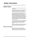
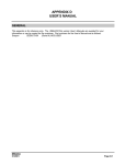
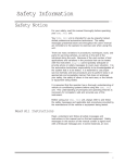
Safety Information
Safety Notice
For your safety, read this manual thoroughly before operating
your ECO Xtreme™ unit.
Your ECO Xtreme™ unit is intended for use by properly trained,
skilled professional automotive technicians. The safety
messages presented below and throughout this user's manual
are reminders to the operator to exercise care when using this
unit.
There are many variations in procedures, techniques, tools, and
parts for servicing vehicles, as well as in the skill of the
individual doing the work. Because of the vast number of test
applications and variations in the products that can be tested
with this instrument, Snap-on® cannot possibly anticipate or
provide advice or safety messages to cover every situation. It is
the automotive technicians responsibility to be knowledgeable of
the system that is to be tested. It is essential to use proper
service methods and test procedures and to perform tests in an
appropriate and acceptable manner that does not endanger
your safety, the safety of others in the work area, the vehicle or
equipment being tested.
It is assumed that the operator has a thorough understanding of
vehicle air conditioning systems before using this ECO
Xtreme™ unit. This understanding of principles and operating
theories is necessary for competent, safe and accurate use of
this instrument.
Before using your ECO Xtreme™ unit, always refer to and
follow the safety messages and applicable test procedures
provided by the manufacturer of the vehicle or equipment being
tested.
Read All Instructions
Read, understand and follow all safety messages and
instructions in this manual and on the test equipment. Safety
messages in this section of the manual contain a signal word
with a three-part message and, in some instances, an icon.
I
Safety Information
The signal word indicates the level of the hazard in a situation.
• DANGER indicates an imminently hazardous situation which,
if not avoided, will result in death or serious injury to the
operator or to bystanders.
• WARNING indicates a potentially hazardous situation which,
if not avoided, could result in death or serious injury to the
operator or to bystanders.
• CAUTION indicates a potentially hazardous situation which, if
not avoided, may result in moderate or minor injury to the
operator or to bystanders.
• IMPORTANT indicates a situation which, if not avoided, may
result in damage to the test equipment or vehicle.
Safety messages in this section contain three different type
styles.
• Normal type states the hazard.
• Bold type states how to avoid the hazard.
• Italic type states the possible consequences of not avoiding
the hazard.
An icon, when present, gives a graphical description of the
potential hazard.
IMPORTANT SAFETY INSTRUCTIONS
Risk of a lack of oxygen.
— Vehicle exhaust gases contain carbon monoxide.
— Refrigerant gas can displace air in work area.
• Use your ECO Xtreme™ unit in locations with
mechanical ventilation providing at least four air
changes per hour.
Impairment of breathing can cause injury.
Power
Risk of electric shock and fire.
• To avoid electric shock the power cord must be
connected to a properly grounded A.C. outlet.
• Do not remove or bypass the grounding pin.
• Use the proper A.C. outlet for the unit to operate
correctly. See the ID plate on the back of the unit.
• Extension cords are not recommended. If an
extension cord must be used, use:
— 16 AWG for cords up to 50', and
— 14 AWG for cords greater than 50' but less
than 100'.
• Do not use on wet surfaces or expose to rain.
• Use only fuses with the rating specified near the
fuse holder.
Electric shock and fire can cause injury.
II
Safety Information
Refrigerant
Risk of expelling refrigerant under pressure.
• Wear safety goggles and protective gloves, user
and bystander. Everyday eyeglasses only have
impact resistant lenses, they are NOT safety
glasses. If any refrigerant gets into the eyes, flush
with water and seek a doctor's aid immediately,
even though irritation may cease.
• Do not remove master filter/dryer while under
pressure. Perform maintenance procedure for
removing master filter/dryer in Chapter
3–Changing the Master Filter/Dryer.
• Prevent refrigerant from contacting the skin.
Expelled refrigerant can cause injury.
Risk of explosion.
• Do not use compressed shop air for leak detection
or to pressure test a system containing
refrigerant. Refrigerant can form combustible
mixtures at pressures above atmospheric and with
air concentrations greater than 60% by volume.
• Do not heat a container of refrigerant above 125°F
(52°C).
Explosion can cause injury.
Risk of fire.
• Do not use this equipment in the vicinity of spilled
or opened containers of gasoline.
• Do not use your ECO Xtreme™ unit or any leak
detector equipment if R-12 substitutes are
suspected. R-12 refrigerant substitutes may be
flammable.
Fire can cause injury.
Risk of poison.
• Avoid breathing air conditioning refrigerant and
lubricant vapor or mist.
• Do not allow refrigerant to contact open flame or
be drawn into a running engine. This can cause
refrigerant to become poisonous phosgene gas.
• Use your ECO Xtreme™ unit to remove refrigerant
from air conditioning systems.
Exposure can irritate eyes, nose and throat.
III
Safety Information
Risk of irritation to mucous membranes.
Avoid breathing air conditioning refrigerant and
lubricant vapor or mist. Exposure may irritate eyes,
nose and throat. To remove HFC-134a from the A/C
system, use service equipment certified to meet the
requirements of SAE J2210 (HFC-134a Recycling
Equipment). Additional health and safety
information may be obtained from the refrigerant
and lubricant manufacturers.
Exposure can irritate eyes, nose and throat.
Oil (Lubricant)
Risk of expelling oil under pressure.
Wear safety goggles and protective gloves, user and
bystander. Everyday eyeglasses only have impact
resistant lenses, they are NOT safety glasses. If any
oil gets into the eyes, flush with water and seek a
doctor's aid immediately, even though irritation may
cease.
Expelled oil can cause injury.
General
Engine systems can malfunction expelling fuel, oil
vapors, hot steam, hot toxic exhaust gases, acid,
refrigerant and other debris.
• Wear safety goggles and protective gloves, user
and bystander. Everyday eyeglasses only have
impact resistant lenses, they are NOT safety
glasses.
• Service should be performed by a certified A/C
service technician.
Engine systems that malfunction can cause injury.
The engine compartment contains electrical connections
and hot or moving parts.
• Keep yourself, test leads, clothing and other
objects clear of electrical connections and hot or
moving engine parts.
• Do not place test equipment or tools on fenders or
other places in the engine compartment.
• Barriers are recommended to help identify danger
zones in test area.
• Prevent personnel from walking through
immediate test area.
Contact with electrical connections and hot or moving
parts can cause injury.
IV
Safety Information
Service hoses can not withstand high temperatures or
severe mechanical stress.
Keep the service hoses away from hot or moving
engine parts.
Service hoses can split or burst causing injury.
Risk of explosion if improper tank is used.
Do not use any tank with this equipment other than
part number EAA0275L05A. These tanks are D.O.T.
certified for refilling. D.O.T certified tanks are
marked "D.O.T. 4BA 350" or "D.O.T. 4BA 400".
Explosion can cause injury.
Removing tubing assemblies may discharge refrigerant.
Wear safety goggles and protective gloves, user and
bystander. Everyday eyeglasses only have impact
resistant lenses, they are NOT safety glasses.
Expelled refrigerant may cause injury.
A test vehicle may move if not properly prepared.
• Block the drive wheels before performing a test
with the engine running. Unless instructed
otherwise, set the parking brake and put the gear
selector in neutral (manual transmission) or park
(automatic transmission). If the vehicle has an
automatic parking brake release, disconnect the
release mechanism for testing and reconnect it
when testing is completed.
• Do not leave a running engine unattended.
A moving vehicle can cause injury.
Risk of explosion.
• Some vehicle fuel systems such as Mercedes,
light trucks, and some Fiat models have the same
service fittings as the A/C systems.
• Do not connect to similar fuel service fittings.
• Connect only to A/C service fittings.
If you mistakenly connect to fuel system:
• Do not use any switches as this may cause
sparks.
• Do not move any metal items as this may cause
sparks.
• Unplug unit’s power cord from the wall outlet.
• Immediately ventilate the work area and call your
local service representative.
Fuel in A/C recovery unit can explode and cause injury.
V
Safety Information
Risk of injury.
• This equipment should be operated by qualified
personnel only.
• Use this equipment only as described in this
manual. Use only the manufacturer’s
recommended attachments.
• Do not operate equipment with a damaged cord or
if the equipment has been dropped or damaged,
until it has been examined by a qualified service
representative. Care should be taken to arrange
the power cord so that it will not be tripped over
or pulled.
• Always unplug equipment from electrical outlet
when not in use. Never use the cord to pull the
plug from the outlet. Grasp the plug and pull to
disconnect.
• Let the equipment cool completely before putting
it away. Loop the power cord loosely in proper
location when storing.
Operation of your ECO Xtreme™ unit by anyone other
than qualified personnel may result in injury.
Risk of refrigerant leakage.
Always close the quick coupler valves before
disconnecting a hose coupling.
Loosened hose couplings can leak refrigerant into the
atmosphere.
Misdiagnosis may lead to incorrect or improper repair
and/or adjustment.
Do not rely on erratic, questionable, or obviously
erroneous test information or results. If test
information or results are erratic, questionable, or
obviously erroneous, make sure that all connections
are correct and that the test procedure was
performed correctly. Refer also to the
Maintenance/Troubleshooting section and perform
tests and make repairs as required. If test
information or results are still suspicious, do not
use them for diagnosis. Contact your Snap-on®
Representative.
Improper repair and/or adjustment may cause vehicle or
equipment damage or unsafe operation.
SAVE THESE INSTRUCTIONS
VI
Table of Contents
Safety .................................................................................................................... I
Introduction ........................................................................................................ 1-1
Refrigerant Gases .................................................................................................................... 1-2
Refrigerant Handling .................................................................................................... 1-3
Refrigerant Safety ...................................................................................................... 1-3
Refrigerant Substitute Warning .................................................................................... 1-4
Refrigerant Oils .......................................................................................................... 1-5
Refrigerant Oil Safety .................................................................................................. 1-5
Functional Description .............................................................................................................. 1-6
Front View .................................................................................................................. 1-6
Back View .................................................................................................................... 1-8
R-134a Accessories .................................................................................................... 1-9
Specifications .......................................................................................................................... 1-10
General .................................................................................................................... 1-10
Operating .................................................................................................................. 1-10
Storage ...................................................................................................................... 1-10
Capacities ................................................................................................................ 1-10
Installation and Operation ................................................................................ 2-1
Connecting Service Hoses to the ECO Xtreme™ Unit ............................................................ 2-1
Preparing and Installing Recovery Tank .................................................................................... 2-2
Tank Preparation ........................................................................................................ 2-2
Power Up .................................................................................................................................. 2-7
Accessing Set-Up .................................................................................................................... 2-8
Adjusting LCD Contrast ........................................................................................ 2-8
Accessing Language ............................................................................................ 2-8
Accessing Master Filter/Dryer Reset ...................................................................... 2-9
Accessing Units of Weight .................................................................................... 2-9
Operation ................................................................................................................................ 2-10
Preliminary Checks .................................................................................................... 2-11
Connecting Service Hoses to Vehicle .................................................................................... 2-12
Recover/Recycle Refrigerant from Vehicle .............................................................................. 2-12
Purging Non-condensable Gas .............................................................................................. 2-14
Evacuating A/C System .......................................................................................................... 2-14
Charging A/C System ............................................................................................................ 2-16
Displaying Refrigerant Amount .............................................................................................. 2-18
Tank Full/Empty ........................................................................................................ 2-18
Removing Recovery Tank ...................................................................................................... 2-19
Recovering Service Hoses ...................................................................................................... 2-19
Evacuating Contaminated Service Hoses .............................................................................. 2-20
Adding Refrigerant to the ECO Xtreme™ Unit ...................................................................... 2-21
Errors and Messages .............................................................................................................. 2-23
i
Table of Contents
Maintenance ...................................................................................................... 3-1
Equipment Tips ............................................................................................................ 3-1
Master Filter/Dryer .................................................................................................................... 3-2
Changing the Master Filter/Dryer ................................................................................ 3-2
Resetting Master Filter/Dryer Monitor .......................................................................... 3-3
Pump ........................................................................................................................................ 3-4
Maintaining the Pump .................................................................................................. 3-4
Storing the ECO Xtreme™ Unit ................................................................................................ 3-7
Troubleshooting ........................................................................................................................ 3-8
Replacement Parts .................................................................................................... 3-10
Optional Accessories ................................................................................................ 3-10
ii
Table of Illustrations
Introduction
Figure 1-1: Front View ............................................................................................................ 1-6
Figure 1-2: Back View .............................................................................................................. 1-8
Figure 1-3: R-134a Accessories .............................................................................................. 1-9
Installation and Operation
Figure 2-1: Recovery Tank and Temperature Probe ................................................................ 2-3
Maintenance
Figure
Figure
Figure
Figure
3-1:
3-2:
3-3:
3-4:
Master Filter/Dryer ................................................................................................
Top Cover Bolt Locations ......................................................................................
Pump Connections ................................................................................................
Lift Pump ..............................................................................................................
3-3
3-4
3-5
3-6
iii
Trademark and Copyright Information
Trademark Acknowledgements
Snap-on® is a registered trademark of Snap-on Technologies, Inc. (USA and Canada)
EquiServ® is a registered trademark of Snap-on Tools Company. (USA)
EquiServ® is a registered trademark of Snap-on Technologies, Inc. (Canada)
ECO Xtreme™ is a trademark of Snap-on Tools Company. (USA and Canada)
Copyright Information
ECO Xtreme™ User’s Manual ©2001 Snap-on Incorporated.
All rights reserved.
The information, specifications and illustrations in this manual are based on the latest
information available at the time of printing. Snap-on reserves the right to make
changes at any time without notice.
iv
Using this Manual
This manual contains instructions for use and set-up of your
ECO Xtreme™ unit. A table of contents and table of
illustrations are provided to make this manual easy to use.
Some of the information shown in text or illustrations is obtained
using optional equipment. A Snap-on® Sales Representative
can determine option availability.
Conventions
This section contains a list of conventions used in text.
Service Hose Couplers and Panel Valves
References in text to opening and closing the service hose
couplers assume:
• Counterclockwise closes the valves, and
• Clockwise opens the valves.
References in text to opening and closing the panel valves
assume:
• Valve pointed up closes the service hose passage, and
• Valve pointed to the left or right opens the service hose
passage.
Check Note
A check note provides additional information about the subject
in the preceding paragraph.
Example:
✓ For additional information refer to Chapter
2–Connecting Service Hoses to the ECO Xtreme™
Unit and Chapter 2–Connecting Service Hoses to
Vehicle.
Equipment Tips
Equipment tips provide information that applies to specific
equipment. Each tip is introduced by this icon ❐ for easy
identification.
Example:
❐ Never attempt to change a recovery tank during unit
operation. For additional information refer to Chapter
2–Removing Recovery Tank.
v
Using this Manual
Equipment Damage
Situations arise during testing that could damage the vehicle or
the test equipment. The word IMPORTANT signals these
situations.
Example:
Failure to follow these instructions could damage
the compressor.
Safety Messages
Safety messages are provided to help prevent personal injury
and equipment damage. All safety messages are introduced by
a signal word indicating the hazard level. The types of safety
messages are:
Indicates an imminently hazardous situation which,
if not avoided, will result in death or serious injury
to the operator or to bystanders.
Indicates a potentially hazardous situation which, if
not avoided, could result in death or serious injury
to the operator or to bystanders.
Indicates a potentially hazardous situation which, if
not avoided, may result in moderate or minor injury
to the operator or to bystanders.
Some safety messages also contain visual symbols with signal
words.
Example:
Engine systems can malfunction expelling fuel, oil
vapors, hot steam, hot toxic exhaust gases, acid,
refrigerant and other debris.
Wear safety goggles and protective gloves, user and
bystander. Everyday eyeglasses only have impact
resistant lenses, they are NOT safety glasses.
Engine systems that malfunction can cause injury.
vi
Using this Manual
Terms
Use the following definitions as a foundation to help understand
your ECO Xtreme™ unit’s processes and/or components.
Virgin Tank
A refrigerant tank, disposable or refillable, that contains new
refrigerant. When empty, a disposable virgin tank must be
evacuated and cannot be refilled. Dispose of this evacuated
tank in accordance with local, state and federal regulations that
apply in your area. A refillable virgin tank should be returned to
your supplier.
Recovery Tank
A refrigerant tank designed to store refrigerant removed from a
virgin tank or recovered from a vehicle. On your ECO Xtreme™
unit, refrigerant is filtered and dried before reaching the
recovery tank. Once in the recovery tank, it is ready for reuse.
Recover
The process of removing refrigerant from a system to prevent
release of refrigerant into the atmosphere. On your ECO
Xtreme™ unit, this process also recycles the refrigerant for
reuse.
Recycle
The process of removing refrigerant from a system, filtering,
drying and storing it in the recovery tank.
✓ Your ECO Xtreme™ unit is a single pass unit.
This
means refrigerant is filtered and dried before reaching
the recovery tank. Once in the recovery tank, it is
ready for reuse. There is no separate "recycle" process
to perform.
Evacuate
The process of drawing a vacuum on a refrigerant system to
remove air and moisture. On your ECO Xtreme™ unit, this
process is known as vacuum.
Charge
The process of filling an air conditioning system with refrigerant.
Purging
The process of bleeding off non-condensable gases from the
recovery tank.
Stable Scale
The situation where the reading from the refrigerant weight
measuring device is steady. Moving your ECO Xtreme™ unit
causes the liquid refrigerant to slosh around in the recovery
tank, resulting in an unsteady scale reading. Avoid moving your
ECO Xtreme™ unit before taking scale readings.
vii
Using this Manual
Panel Valve Symbols
OFF Low-Side
Left panel valve pointed towards this symbol indicates the blue,
low-side service hose passage is closed to unit operations while
still registering vehicle A/C system pressure on the gauge.
CHARGE Low-Side
Left panel valve pointed towards this symbol indicates
refrigerant being charged through the low-side service hose.
RECOVER/VACUUM Low-Side
Left panel valve pointed towards this symbol indicates system
being recovered or evacuated through the low-side service
hose.
OFF High-Side
Right panel valve pointed towards this symbol indicates red,
high-side service hose passage is closed to unit operations
while still registering vehicle A/C system pressure on the gauge.
CHARGE High-Side
Right panel valve pointed towards this symbol indicates
refrigerant being charged through the high-side service hose.
RECOVER/VACUUM High-Side
Right panel valve pointed towards this symbol indicates system
being recovered or evacuated through the high-side service
hose.
viii
1
Introduction
Use your ECO Xtreme™ unit on automotive air conditioning
systems to:
• Recover,
— Remove refrigerant from vehicle,
• Recycle,
— Filter, dry and store recovered refrigerant in a refillable
tank,
• Evacuate,
— Remove air and moisture from air conditioning system
using a vacuum to draw the system into a deep vacuum,
and
• Recharge,
— Refill the air conditioning system with a specified amount
of refrigerant.
Your ECO Xtreme™ unit is a single pass design. This means
recovered refrigerant is filtered and dried before entering the
recovery tank. Refrigerant in the tank is always ready for use.
Refer to Chapter 2–Recovering Refrigerant From Vehicle. There
is no need to perform a separate recycle function. Recover,
evacuate and recharge functions are performed semiautomatically.
This manual applies to the following ECO Xtreme™ model:
Model Number
EEAC316A
Refrigerant Type
R-134a
Voltage
120 VAC
Your ECO Xtreme™ unit includes:
• A Liquid Crystal Display (LCD) and four buttons to control
operation,
• Integral gauge set and manual control valves with service
hoses, fittings, and adapters,
• A 50 pound capacity recovery tank and electronic scale,
• Master filter/dryer with automatic replacement reminder, and
• An oil drain bottle.
✓ The recovery tank is temperature-monitored to maintain
accurate purging of non-condensable gases under all
conditions.
1-1
Introduction
Refrigerant Gases
Halogens are any of the five elements (fluorine, chlorine,
bromine, iodine and astatine) that form part of group 7a of the
Periodic Table of Elements. The fluorine and chlorine elements
of this family are used to create a methane organic compound
used to form dichlorodifluoromethane (CCL2F2 ), a halogenated
hydrocarbon called CFC-12 (chlorofluorocarbon 12). This
refrigerant gas is commonly known as Refrigerant-12, or R-12,
and has been used as a refrigerant in mobile air conditioning
systems for many years.
The new refrigerant in the halogenated hydrocarbon family,
HFC-134a (CH2FCF3 ), or R-134a, is now being incorporated in
mobile air conditioning systems. HFC stands for
hydrofluorocarbon.
The environmental impact of mobile air conditioning refrigerant
containing chlorine (R-12) has caused regulatory action that will
eventually eliminate the use of such products. Regulatory
action is necessary because when the chlorine content in R-12
is exposed to the atmosphere:
• It depletes the protective ozone layer in the atmosphere,
• It has relatively high global warming potential, and
• Its long atmospheric lifetime is approximately 120 years.
R-134a has been developed for new vehicle production but does
not replace or directly substitute for R-12 in existing vehicles.
R-134a does not contain chlorine, does not deplete the ozone
layer in the atmosphere and has an atmospheric lifetime of
about 15.5 years.
Environmental Protection Agency (EPA) and state regulations
specify that:
• Provisions be made to certify all air conditioning service,
installation and repair personnel,
• Refrigerant be recovered, recycled or reclaimed from
automotive air conditioning systems, instead of allowing
vapors to be expelled, or vented, into the atmosphere, and
• Refrigerant be recycled and reused, or properly disposed of,
instead of allowing vapors to be expelled, or vented, into the
atmosphere.
Mobile air conditioning service, installation and repair
technicians must be qualified and certified.
1-2
Introduction
Refrigerant Handling
Mobile air conditioning systems contain chemical mixtures that
require special handling to avoid injury and to avoid venting
refrigerant into the atmosphere.
Do not discharge any refrigerant gas, vapor or liquid from a
refrigeration system into the atmosphere. If service is required
that involves opening the refrigerant system, use a certified
recovery system.
Refrigerant Safety
• Wear safety goggles and protective gloves, user
and bystander. Everyday eyeglasses only have
impact resistant lenses, they are NOT safety
glasses. If any refrigerant gets into the eyes, flush
with water and seek a doctor's aid immediately,
even though irritation may cease.
• Do not remove master filter/dryer while under
pressure. Follow instructions for removing master
filter/dryer. For additional information refer to
Chapter 3–Changing the Master Filter/Dryer .
• Prevent refrigerant from contacting the skin.
• Read, understand and follow Safety Information in
the front of this manual.
• Use your ECO Xtreme™ unit in locations with
mechanical ventilation providing at least four air
changes per hour.
• Avoid breathing air conditioning refrigerant and
lubricant vapor or mist.
• Do not allow refrigerant to contact open flame or
be drawn into a running engine. This can cause
refrigerant to become poisonous phosgene gas.
• Use your ECO Xtreme™ unit to remove refrigerant
from air conditioning systems.
• Read, understand and follow Safety Information in
the front of this manual.
• Tighten all connections properly. Insufficient or
excessive torque can result in loose joints or
deformed parts. Either condition can result in
refrigerant leakage.
1-3
Introduction
Refrigerant Substitute Warning
• Do not use your ECO Xtreme™ unit or any leak
detector equipment if R-12 substitutes are
suspected. R-12 refrigerant substitutes may be
flammable.
• Read, understand and follow Safety Information in
the front of this manual.
Aftermarket R-12 refrigerant substitutes are being sold that are
dangerous or potentially flammable gases. These products
contain a blend of butane, isobutane and propane and have the
potential for explosion. Some of these products are:
• OZ-12,
• Refrigerant-176,
• Arctic Chill R-176, and
• GHG Refrigerant 12.
Some vehicles using OZ-12 can be identified by a label that
may be placed in the engine compartment, but many cannot be
identified. Studies are currently being conducted to develop a
procedure to identify the type of refrigerant in a refrigerant
system. State agencies and the Environmental Protection
Agency (EPA) are moving to ban flammable substitutes.
If it is suspected that a refrigerant system contains a product of
this type:
• Question the customer about previous service,
• Be aware of any unfamiliar odor from the system,
• Do not use any leak detector equipment,
• Do not use recycling equipment, and
• Contact your state fire marshall or local EPA office.
1-4
Introduction
Refrigerant Oils
In mobile air conditioning units, the lubricant needed for the
compressor is blended with the refrigerant. Mineral (petroleum)
oils were used with R-12 systems. Mineral oils are not soluble
in R-134a and the industry had to substitute synthetic
lubricating fluids for the mineral oils. Polyalkylene glycol oils
(PAGs) were the first synthetics to meet the auto A/C
compressor manufacturers performance criteria, and most
automakers and compressor manufacturers devised their retrofit
specifications with PAGs in mind. Since then, polyol ester oils
(ESTERS or POEs) have been tested and also have been found
to meet the performance criteria. Although POEs have not been
approved by the automakers or A/C compressor manufacturers,
POEs are frequently used in A/C retrofits in the automotive
aftermarket.
Refrigerant Oil Safety
Risk of irritation of mucous membranes.
• Wear safety goggles and protective gloves, user
and bystander. Everyday eyeglasses only have
impact resistant lenses, they are NOT safety
glasses. If any refrigerant gets into the eyes, flush
with water and seek a doctor's aid immediately,
even though irritation may cease.
• Avoid breathing A/C refrigerant and lubricant
vapor or mist. Exposure may irritate eyes, nose
and throat. To remove HFC-134a from the A/C
system, use service equipment certified to meet
the requirements of SAE J2210 (HFC-134a
Recycling Equipment). Additional health and
safety information may be obtained from
refrigerant and lubricant manufacturers.
Exposure can irritate eyes, nose and throat.
1-5
Introduction
Functional Description
Front View
Figure 1-1: Front View
✓ DO NOT lift the ECO Xtreme™ unit by top plastic
cover.
A — Integral Gauge Set
High and low pressure, panel mounted gauge set for monitoring
vehicle A/C system pressures.
Control Panel
Houses display screen, indicator light and control buttons.
B — Liquid Crystal Display (LCD) Screen
Displays alpha-numeric information and key labels. Shows
charged, recovered amounts or chargeable weight of the
recovery tank. Also indicates software version, “Tank Full”, and
“Tank Empty” conditions.
1-6
Introduction
C — Control Buttons
Four buttons are used to enter information and control the ECO
Xtreme™ system operation:
• UP and DOWN buttons are used to select menu options on
the screen.
• Two buttons with variable functions depending on the screen
display.
D — Two Panel Valves
Used to select OFF, CHARGE, or RECOVER/VACUUM. Right
panel valve opens and closes the high-side service hose
passage to your ECO Xtreme™ unit. Left panel valve opens
and closes the low-side service hose passage to your ECO
Xtreme™ unit.
E — LED Light
• Lights when the unit is first turned ON,
• Lights to indicate end of evacuation, and
• Blinks to indicate error conditions.
F — Oil Separator (internal)
Removes oil and other contaminants from the refrigerant being
recycled.
G — Oil Drain Valve
Used to drain recovered oil from the unit after every
recover/recycle operation.
H — Oil Drain Bottle
Used to measure the amount of recovered oil.
1-7
Introduction
Back View
Figure 1-2: Back View
A — Main Power Switch
Turns power ON and OFF. Must be on ( I ) for unit operation.
B — Master Filter/Dryer
Consists of a 10 micron particulate filter and desiccant to
remove moisture. For additional information refer to Chapter
3–Changing the Master Filter/Dryer.
C — Scale
Electronically measures the amount of refrigerant dispensed,
recycled, and remaining in the recovery tank.
D — Recovery Tank
Holds refrigerant from a vehicle A/C service and supplies
refrigerant for charging.
E — Service Port, High-Side
For connecting to high pressure side of vehicle A/C system.
Service Port, Low-Side
For connecting to low pressure side of vehicle A/C system.
1-8
Introduction
R-134a Accessories
Figure 1-3: R-134a Accessories
A — Service Hoses
Red and blue hoses with shut-off adapters for your ECO
Xtreme™ unit to connect to the vehicle. For additional
information refer to Chapter 2–Connecting Service Hoses to the
ECO Xtreme™ Unit and Chapter 2–Connecting Service Hoses
to Vehicle.
B — Auto Shut-off Adapters (Couplers)
1 - Connects to high- and low-side service ports of vehicle.
2 - Quick connect/disconnect valve actuation without refrigerant
venting. Couplers contain manual shut-off hand valves to
control flow of refrigerant while connected to service ports and
prevent blow-back while connecting/disconnecting hoses.
C — Low-Side Adapter Fitting
Adapter, part number 1-15080, to connect low-side service hose
to a refrigerant tank for adding refrigerant to the ECO Xtreme™
unit or for new tank preparation.
1-9
Introduction
Specifications
General
Power
120 VAC, 60 Hz, 6 amps maximum
Shipping Weight
175 lbs (79.38 kg)
Dimensions
Depth
Height
Width
29"
46"
23"
Operating
Operating Temperature Range
50–120°F (10–49°C) ambient
Relative Humidity
Up to 80%, non-condensing
Maximum Operating Pressure
450 psi
Pressure Range
30 inHg–300 psi
Storage
Storage Temperature Range
-4–140°F (-20–60°C) ambient
Relative Humidity
Up to 80%, non-condensing
Capacities
Refrigerant Charge Amount
0–42 lbs (19.05 kg)
Recovery Amount
0–45 lbs (20.41 kg)
Recycled Refrigerant Tank
50 lb with purge port
1-10
Installation
and Operation
2
Use the information in this chapter to:
• Prepare your ECO Xtreme™ unit for initial use,
• Recover vehicle refrigerant,
• Create a vacuum before recharging, and
• Recharge with recycled refrigerant.
Connecting Service Hoses to the
ECO Xtreme™ Unit
Use the following procedure to connect service hoses to your
ECO Xtreme™ unit.
• Do not use your ECO Xtreme™ unit or any leak
detector equipment if R-12 substitutes are
suspected. R-12 refrigerant substitutes may be
flammable.
• Read, understand and follow Safety Information in
the front of this manual.
• Refer to page 1-4.
✓ Confirm refrigerant type in vehicle, and use the
appropriate connections on the unit.
✓ Always lubricate rubber gaskets and seals at hose
connections with fresh refrigerant oil before connecting.
✓ Tighten hose connections finger tight, including master
filter/dryer connections. Use electronic leak detector to
insure connections are leak free.
1. Connect the high (red) and low (blue) couplers to their
respective hoses. Rotate coupler knobs fully CCW
(closed).
2. Attach other end of red hose to upper, red labeled (highside) port on the back panel of the ECO Xtreme™ unit.
3. Attach other end of blue hose to lower, blue labeled (lowside) port on the back panel of the ECO Xtreme™ unit.
2-1
Installation and Operation
Preparing and Installing Recovery Tank
The recovery tank is shipped with a dry air charge. The charge
must be vented and the tank evacuated before use. Use the
following procedure to evacuate the dry air from the recovery
tank and install it in your ECO Xtreme™ unit.
• Do not use any tank with this equipment other
than part number EAA0275L05A. These tanks are
D.O.T. certified for refilling. D.O.T certified tanks
are marked "D.O.T. 4BA 350" or "D.O.T. 4BA 400".
• Read, understand and follow Safety Information in
the front of this manual.
Vent and evacuate the recovery tank before first use.
An unprepared tank can cause compressor burnout.
✓ The recovery tank must have a minimum of 25 inHg
vacuum when evacuation is complete. If there is not
25 inHg vacuum, check connections and repeat the
procedure.
Tank Preparation
Follow this procedure to install a new recovery tank in your ECO
Xtreme™ unit. New recovery tanks are charged with dry air
which must be vented before using.
• Wear safety goggles, user and bystander.
Everyday eyeglasses only have impact resistant
lenses, they are NOT safety glasses.
• Cover the blue hand valve port with a shop towel
to help prevent debris from becoming projectiles.
• Read, understand and follow Safety Information in
the front of this manual.
1. Vent dry air by slowly opening blue hand valve on the
recovery tank.
2. Gently set the recovery tank on the scale with the hand
valves up, facing the back of the unit.
3. Place the velcro strap securely around the recovery tank.
2-2
Installation and Operation
Figure 2-1: Recovery Tank and Temperature Probe
✓ Use only the 50 pound capacity recovery tank supplied
with your ECO Xtreme™ unit or one indicated by the
warning label on the back of the unit. Inaccurate
refrigerant amount may display if the correct tank is not
used. Using any other type or capacity tank could
create the danger of explosion and potential for
personal injury.
4. Connect tank adapter, part number 1-15080, to liquid
(blue) port of recovery tank (port nearest to the blue
hand valve).
5. Connect blue service hose from low-side port of the ECO
Xtreme™ unit to installed tank adapter.
6. Open the following:
— Blue (liquid) recovery tank valve, and
— Blue service hose coupler (CW).
7. Turn both panel valves to OFF.
8. Connect the power cord to the proper wall outlet with the
correct voltage for the unit. For additional information
refer to Power Up in this chapter and Chapter 1Specifications.
9. Turn power switch ON. The following screens will
display:
— Software Version screen, and
— Main Menu screen.
2-3
Installation and Operation
✓ In the unlikely event the LCD screen is unreadable or a
different language is displayed upon power up, adjust
LCD contrast or change language selection. Refer to
Adjusting LCD Contrast or Accessing Language in this
chapter.
10. Select VACUUM and press ENTER, the following
message displays:
OPEN PANEL VALVES
. . . VACUUM . . .
TIMER
xx:xx
UP/DOWN TO ADJUST TIME
Press UP/DOWN buttons to adjust time to desired value.
11. Turn the left, low-side panel valve to VACUUM, press
START.
12. Monitor the low side panel gauge until a minimum of
25 inHg of vacuum is reached.
13. Close the following:
— Blue (liquid) recovery tank valve, and
— Blue service hose coupler (CCW).
14. Press EXIT and the following message displays:
CLOSE PANEL VALVES
THEN PRESS NEXT.
15. Turn the left, low-side panel valve to OFF and press
NEXT.
16. Remove the blue service hose from the tank. Remove
the tank adapter 1-15080.
17. Identify the yellow hose leading from the bottom of the
unit. Connect the hose end to the tank purge port.
Rotate the tank so the valves face towards the back of
the unit.
18. Identify the red hose leading from the bottom of the unit.
Connect the hose end with the anti-blowback valve to the
red (vapor) tank port.
19. Open the red (vapor) recovery tank valve.
2-4
Installation and Operation
20. Identify the blue hose leading from the bottom of the unit.
Connect the hose end with the anti-blowback valve to the
blue (liquid) tank port.
21. Open the blue (liquid) recovery tank valve.
22. Connect tank adapter, part number 1-15080, to port of
virgin refrigerant tank.
23. Connect the blue service hose from low-side port of the
ECO Xtreme™ unit to installed tank adapter.
✓ Position the virgin tank with the valve up.
Do not use
the virgin tank with the valve underneath the tank.
✓ Do not recover liquid refrigerant from a supply tank.
24. Open the following:
— Virgin tank hand valve, and
— Blue service hose coupler (CW).
25. Select RECOVER and press ENTER, the following
message displays:
OPEN PANEL VALVES
. . . RECOVER . . .
AMOUNT RECOVERED
xx lb
xx oz
26. Turn the left, low-side panel valve to RECOVER, press
START.
The refrigerant flows from the virgin tank through your
ECO Xtreme™ unit and into the prepared recovery tank.
✓ A minimum of 6 lbs. of refrigerant needs to be in the
recovery tank before a charge operation can be
accomplished. Refer to Tank Full/Empty in this chapter.
27. When the desired amount of refrigerant has been
transferred into the recovery tank, close the virgin tank
hand valve.
2-5
Installation and Operation
Risk of expelling refrigerant under pressure.
• Always close the tank valves before removing the
hoses or fittings.
• Wear safety goggles and protective gloves, user
and bystander. Everyday eyeglasses only have
impact resistant lenses, they are NOT safety
glasses. If any refrigerant gets into the eyes, flush
with water and seek a doctor's aid immediately,
even though irritation may cease.
• Prevent refrigerant from contacting the skin.
Expelled refrigerant can cause injury.
28. Allow the recover/recycle operation to run until 15 inHg
vacuum is reached. Then close the blue service hose
coupler.
29. Press EXIT when complete, the following message
displays:
CLOSE PANEL VALVES
THEN PRESS NEXT.
30. Turn the left, low-side panel valve to OFF and press
NEXT, the following messages display:
PLEASE WAIT . . .
. . . .
DRAIN OIL AND
RECORD AMOUNT . . .
31. Drain waste oil by slowly opening the oil drain valve. Any
accumulated oil expels into the bottle.
32. Close the valve immediately when all of the oil is
expelled.
✓ Discard refrigerant oil in accordance with local, state
and federal regulations that apply in your area.
33. Press NEXT and the following message displays:
PLEASE WAIT . . .
. . . PURGING AIR
After purging, the ECO Xtreme™ unit will display Main Menu.
2-6
Installation and Operation
Power Up
Refer to this section to understand the power up sequence of
the ECO Xtreme™ unit.
1. Connect the power cord to the proper wall outlet with the
correct voltage for the unit. For additional information
refer to Chapter 1–Specifications.
2. Turn power switch ON.
3. The ECO Xtreme™ unit will power up. The following
screens will appear in order:
— Software Version screen:
Snap-on Diagnostics
ECO Xtreme
Software Rev
(C)2000 Snap-on
— Main Menu screen with default arrow position:
➜ RECOVER
• CHARGE
• VACUUM
• SET-UP
------------------------------------(ENTER)
(AMOUNTS)
✓ In the unlikely event the LCD screen is unreadable or a
different language is displayed upon power up, adjust
LCD contrast or change language selection. Refer to
Adjusting LCD Contrast or Accessing Language in this
chapter.
2-7
Installation and Operation
Accessing Set-Up
Adjusting LCD Contrast
Use the procedure in this section to adjust the contrast on the
LCD screen, with or without being able to read the screen.
1. Power up the ECO Xtreme™ unit.
✓ Wait until red LED is OFF.
2. Press UP button once to select SET-UP from the Main
Menu and then press ENTER, the left button under the
LCD display.
3. Select CONTRAST from the Set-Up Menu, press ENTER.
— CONTRAST will be the default selection when the
Set-Up Menu screen displays:
➜ CONTRAST
• lbs/kg
• LANGUAGE
•– – –
• FILTER
•– – –
------------------------------------(ENTER)
(EXIT)
4. Press ENTER a second time to automatically reset LCD
contrast to default settings, or press UP button to lighten
contrast or DOWN button to darken it.
5. Press EXIT twice to return to Main Menu.
Accessing Language
Use the procedure in this section to change the language
selection of the ECO Xtreme™ unit.
1. Power up the ECO Xtreme™ unit.
✓ Wait until red LED is OFF.
2. Press UP button once to select SET-UP from the Main
Menu and then press ENTER, the left button under the
LCD display.
3. Press DOWN button once to select LANGUAGE from the
Set-Up Menu, press ENTER.
• CONTRAST
• lbs/kg
➜ LANGUAGE
•– – –
• FILTER
•– – –
------------------------------------(ENTER)
(EXIT)
4. Press UP or DOWN button to scroll through language
selections.
5. Press SAVE/EXIT to select a language.
2-8
Installation and Operation
Accessing Master Filter/Dryer Reset
Use the procedure in this section to reset the automatic
reminder monitor for the master filter/dryer.
✓ This procedure should only be done when the master
filter/dryer is replaced.
1. Power up the ECO Xtreme™ unit.
✓ Wait until red LED is OFF.
2. Select SET-UP from the Main Menu, press ENTER.
3. Select FILTER from the Set-Up Menu, press ENTER.
4. Press RESET button.
5. Press CONFIRM to reset the master filter/dryer reminder
monitor.
Accessing Units of Weight
Use the procedure in this section to change the refrigerant unit
of weight measurement.
1. Power up the ECO Xtreme™ unit.
✓ Wait until red LED is OFF.
2. Select SET-UP from the Main Menu, press ENTER.
3. Select lbs/kg from the Set-Up Menu, press ENTER.
4. Press UP or DOWN button to scroll through lb-oz, lb, kg
or oz.
5. Press SAVE/EXIT to select a unit of measurement.
2-9
Installation and Operation
Operation
This section contains:
• Procedures for connecting the service hoses to the vehicle,
and
• Procedures to:
— Recover vehicle refrigerant,
— Create a vacuum in the A/C system before recharging,
and
— Recharge the A/C system with recycled refrigerant.
After performing all of the installation procedures, follow these
recommended vehicle service procedures before using your
ECO Xtreme™ unit for A/C work.
Keep the service hoses away from moving or hot
engine parts. The service hoses can not withstand
high temperatures or severe mechanical stress.
• Close the tank valves when not using your ECO
Xtreme™ unit. Leaving tank valves open may
result in refrigerant loss from tank.
• Do not use your ECO Xtreme™ unit outside of the
following limits:
— Warmer than 120°F (49°C),
— Colder than 50°F (10°C), and/or
— Relative humidity greater than 80%.
• Stabilize your ECO Xtreme™ unit to a moderate
temperature and inspect for abnormalities.
• Contact your Snap-on® representative before
operating if unsure of condition.
• Operating your ECO Xtreme™ unit with the
following conditions may reduce its functionality:
— Visible evidence of damage,
— Has been subjected to prolonged storage
under unfavorable conditions, or
— Has been subjected to severe transportation
stresses.
2-10
Installation and Operation
Preliminary Checks
Successful use of your ECO Xtreme™ unit depends on several
external factors. The following information explains these.
Precondition Vehicle
The refrigerant in the vehicle A/C system is recovered faster
and more completely when the components are warm.
1. Connect the service hoses to the vehicle, refer to
Connecting Service Hoses to Vehicle in this chapter.
To efficiently recover refrigerant, the vehicle should be at normal
operating temperature. Run the engine until normal operating
temperature is reached, with
• The A/C system OFF, and
• The hood lowered as much as possible without damaging or
crimping the service hoses.
2. Turn off the engine when normal operating temperature
is reached. The unit and vehicle are ready to recover
and recycle refrigerant.
Allow Adequate Evacuation Time
Evacuate the vehicle A/C system for a minimum of 30 minutes.
This helps ensure vehicle A/C system is free of noncondensable gases (mostly air) and moisture.
✓ Sometimes a small amount of refrigerant is left in the
vehicle A/C system that is not practical to recover. If
recovery time is too short or if vehicle components are
cold, this parasitic refrigerant can expand during a
vacuum hold cycle or a leak test, and falsely report a
leak condition that does not exist.
Follow Vehicle Manufacturer’s A/C Service Procedures
When charging, a slow charge condition may occur due to
pressure equalization between your ECO Xtreme™ unit and the
vehicle A/C system. Finish charging by:
• Turn the panel valves to OFF,
• Starting the engine,
• Turning the A/C system ON,
• Turn the left, low-side panel valve to CHARGE, and
• Monitor the charge weight and close the panel valve when the
desired charge weight is reached.
✓ Never operate the vehicle A/C system with the highside panel valve open.
✓ It is the technician’s responsibility to be familiar with
vehicle manufacturer recommended service
procedures.
2-11
Installation and Operation
Connecting Service Hoses to Vehicle
Follow this procedure to connect the service hoses to the
vehicle.
1. Connect the red, high-side service hose from the ECO
Xtreme™ unit to the high-side service port on the
vehicle.
2. Connect the blue, low-side service hose from the ECO
Xtreme™ unit to the low-side service port on the vehicle.
✓ If the vehicle has more than one low-side service port,
use the service port closest to the evaporator.
3. Open the service hose couplers.
— Refer to the vehicle manufacturer’s service manual
for proper diagnostic procedures and specifications.
Recover/Recycle Refrigerant from Vehicle
✓ Be sure that the vehicle is at normal operating
temperature before recovering refrigerant.
1. Open the blue (liquid) and red (vapor) recovery tank
valves.
2. Connect the service hoses to the vehicle and open
service hose couplers. For additional information refer to
Connecting Service Hoses to Vehicle in this chapter.
3. Select RECOVER and press ENTER, the following
message displays:
OPEN PANEL VALVES
. . . RECOVER . . .
AMOUNT RECOVERED
xx lb
xx oz
4. Turn both panel valves to RECOVER, press START.
Refrigerant flows from the vehicle, through your ECO
Xtreme™ unit, and into the recovery tank.
As refrigerant is recovered, the panel gauges show
increasing vacuum. Continue recovering until the lowside manifold gauge indicates 15 inHg.
2-12
Installation and Operation
5. Press PAUSE and the following message displays:
PAUSED . . .
If vehicle A/C system components show evidence of
icing, gently warm the component to facilitate refrigerant
removal.
Monitor the low-side manifold pressure gauge for about 5
minutes.
— No change indicates recovery is complete. Go to
next step.
— A pressure increase above vacuum (0 psi) indicates
more recovery time is required. Repeat system
operation until system pressure remains stable at
vacuum for 2 minutes. Press START to continue
recovering.
If a vehicle A/C system leak is suspected, add a partial
charge to the system and leak test with an electronic
leak detector to find the leak. Recover refrigerant when
done testing.
6. Press EXIT when complete, the following message
displays:
CLOSE PANEL VALVES
THEN PRESS NEXT.
7. Turn both panel valves to OFF and press NEXT, the
following messages display:
PLEASE WAIT . . .
. . . .
DRAIN OIL AND
RECORD AMOUNT . . .
8. Drain waste oil by slowly opening the oil drain valve. Any
accumulated oil expels into the bottle.
9. Close the valve immediately when all of the oil is
expelled. The amount indicated on the bottle is the
amount to add back into the vehicle A/C system when
recharging.
✓ Discard refrigerant oil in accordance with local, state
and federal regulations that apply in your area.
2-13
Installation and Operation
10. Press NEXT, the following message displays:
PLEASE WAIT . . .
. . . PURGING AIR
11. When Main Menu screen appears, close the red and blue
service hose couplers.
Purging Non-condensable Gas
✓ Purging non-condensable gases is an automatic feature
executed by the ECO Xtreme™ unit.
Evacuating A/C System
Use this procedure to remove non-condensible gases and
moisture from the vehicle A/C system.
1. Open the blue (liquid) and red (vapor) recovery tank
valves.
2. Connect the service hoses to the vehicle and open
service hose couplers. For additional information refer to
Connecting Service Hoses to Vehicle in this chapter.
✓ If the gauges indicate pressure, recover refrigerant
from the service hoses before proceeding. Refer to
Recovering Service Hoses in this chapter.
3. Select VACUUM and press ENTER, the following
message displays:
OPEN PANEL VALVES
. . . VACUUM . . .
TIMER
xx:xx
UP/DOWN TO ADJUST TIME
Press UP/DOWN buttons to adjust time to desired value.
2-14
Installation and Operation
4. Turn both panel valves to VACUUM, press START.
The panel gauges show vacuum increasing.
✓ Follow the manufacturer recommendations for
evacuation time, usually at least 30 minutes.
When evacuation time is done, LED will light and the
following message displays:
FINISHED . . .
5. Press EXIT and the following message displays:
CLOSE PANEL VALVES
THEN PRESS NEXT.
6. Turn both panel valves to OFF and press NEXT, the
following message displays:
PLEASE WAIT . . .
7. Monitor the low-side pressure for 5 minutes.
Any rise in vacuum indicates a leak in the vehicle
system.
✓ If the source of the leak cannot be determined, partially
charge the system and perform a leak test using an
electronic leak detector.
8. When the leak is identified, repeat Recover/Recycle
procedure, repair the leak and attempt the Evacuation
procedure again.
Evacuation is complete.
2-15
Installation and Operation
Charging A/C System
✓ When charging a vehicle after evacuation, allow for the
capacity of the hoses. Each hose holds approximately
two ounces of refrigerant, so the charge amount should
be increased by two ounces for each hose used.
— If there is not enough refrigerant in the recovery tank
to charge, refer to Adding Refrigerant to the ECO
Xtreme™ Unit in this chapter.
1. Open the blue (liquid) and red (vapor) recovery tank
valves.
2. Connect the service hoses to the vehicle and open
service hose couplers. For additional information refer to
Connecting Service Hoses to Vehicle in this chapter.
3. Select CHARGE and press ENTER, the following
message displays:
CHARGE VEHICLE
WITH PANEL VALVES
xx lb
xx oz
4. Turn the right, high-side panel valve to CHARGE.
Refrigerant flows from the recovery tank into the vehicle.
5. Monitor the charge weight. When the desired charge
weight is reached, turn the right, high-side panel valve to
OFF.
The refrigerant flow stops.
✓ When charging, a slow charge condition may occur due
to pressure equalization between your ECO Xtreme™
unit and the vehicle A/C system. Finish charging by:
— Turn the panel valves to OFF,
— Starting the engine,
— Turning the A/C system ON,
— Turn the left, low-side panel valve to CHARGE, and
— Monitor the charge weight and close the panel
valve when the desired charge weight is reached.
✓ Never operate the vehicle A/C system with the highside panel valve open.
6. Monitor the high- and low-side system pressures. Refer
to the manufacturer’s specifications for proper operation
and diagnosis.
2-16
Installation and Operation
7. Press EXIT when complete, the following message
displays:
DO YOU WANT
TO RECOVER
HOSES NOW?
(YES)
(NO)
8. If YES, the following message displays:
DISCONNECT HOSES.
SET PANEL VALVES
TO RECOVER.
9. Close the service hose couplers to recover the hoses
and press NEXT, the following message displays:
RECOVERING . . .
AMOUNT RECOVERED
xx lb
xx oz
10. Allow the recycler to run until 15 inHg vacuum is
reached.
11. Press EXIT when complete, the following message
displays:
CLOSE PANEL VALVES
THEN PRESS NEXT.
12. Turn both panel valves to OFF and press NEXT, the
following message displays:
PLEASE WAIT . . .
. . . PURGING AIR
Charge is complete.
2-17
Installation and Operation
Displaying Refrigerant Amount
Use this procedure to determine the amount of refrigerant in the
recovery tank and the amount able to be charged.
1. Press the AMOUNTS button to obtain RECOVERED and
CHARGED amounts.
2. Press the MORE button to obtain TANK amount and
FILTER/DRYER percentage.
TANK amount is the total weight of the chargeable
refrigerant in the recovery tank. Approximately 3 lbs of
refrigerant is needed to meet the quill tube in the tank.
This makes the “Tank Empty” point 3 lbs. Any refrigerant
over this amount is usable for charging.
FILTER/DRYER percentage is the percentage left before
the master filter/dryer needs to be replaced. This
percentage number counts down from 100%.
Tank Full/Empty
Messages display when the recovery tank is full or empty.
✓ The unit may only be used to charge an A/C system
when the recovery tank is full.
✓ The unit may be used to recover/recycle or evacuate an
A/C system when the recovery tank is empty.
✓ “Tank Empty” is displayed when the weight in the
recovery tank is less than approximately 3 lbs.
✓ “Tank Full” is displayed when the Chargeable amount of
refrigerant in the recovery tank is above 45 lbs.
2-18
Installation and Operation
Removing Recovery Tank
✓ Ensure both valves on the recovery tank are closed.
1. Disconnect the hoses from the recovery tank.
2. Remove the velcro strap on the recovery tank.
3. Gently remove the recovery tank from the scale.
Recovering Service Hoses
Recover the service hoses before removing them from the ECO
Xtreme™ unit. Service hoses are not connected to a vehicle
during this procedure.
1. Connect the power cord to the proper wall outlet with the
correct voltage for the unit. For additional information
refer to Chapter 1–Specifications.
2. Turn power switch ON.
3. Select RECOVER and press ENTER, the following
message displays:
OPEN PANEL VALVES
. . . RECOVER . . .
AMOUNT RECOVERED
xx lb
xx oz
4. Turn both panel valves to RECOVER, press START.
Refrigerant flows through your ECO Xtreme™ unit, and
into the recovery tank.
5. Monitor the high- and low-side panel gauges.
Service hose recovery is complete when 15 inHg of
vacuum is reached.
6. Press EXIT when complete, the following message
displays:
CLOSE PANEL VALVES
THEN PRESS NEXT.
2-19
Installation and Operation
7. Turn both panel valves to OFF and press NEXT, the
following messages display:
PLEASE WAIT . . .
. . . .
DRAIN OIL AND
RECORD AMOUNT . . .
8. Drain waste oil by slowly opening the oil drain valve. Any
accumulated oil expels into the bottle.
9. Close the valve immediately when all of the oil is
expelled.
✓ Discard refrigerant oil in accordance with local, state
and federal regulations that apply in your area.
10. Press NEXT and the following message displays:
PLEASE WAIT . . .
. . . PURGING AIR
After purging, the ECO Xtreme™ unit will display Main Menu.
Service hose recovery is complete.
Evacuating Contaminated Service
Hoses
✓ If contaminated refrigerant or refrigerant other than
R-134a is present in service hoses, use separate
recover only machine to collect refrigerant.
2-20
Installation and Operation
Adding Refrigerant to the ECO Xtreme™
Unit
Follow this procedure to add virgin or recycled refrigerant to
your ECO Xtreme™ unit.
✓ The recovery tank should have at least six pounds of
refrigerant or the charge procedure may not be
completed.
1. Refer to Preparing and Installing Recovery Tank in this
chapter.
2. Open the blue (liquid) and red (vapor) recovery tank
valves.
✓ Install the supplied tank adapter, part number 1-15080,
between the tank valve and the blue service hose. The
virgin tank should be upright (valve up).
✓ Do not recover liquid refrigerant from a supply tank.
3. Connect the blue service hose from the ECO Xtreme™
unit to the refrigerant supply tank.
4. Open the following:
— Supply tank valve, and
— Blue service hose coupler.
5. Connect the power cord to the proper wall outlet with the
correct voltage for the unit. For additional information
refer to Power Up in this chapter and Chapter
1–Specifications.
6. Turn power switch ON.
7. Select RECOVER and press ENTER, the following
message displays:
OPEN PANEL VALVES
. . . RECOVER . . .
AMOUNT RECOVERED
xx lb
xx oz
8. Turn the left, low-side panel valve to RECOVER, press
START.
The refrigerant flows from the virgin tank through your
ECO Xtreme™ unit and into the prepared recovery tank.
2-21
Installation and Operation
✓ Monitor the weight on the LCD display until the desired
amount of virgin refrigerant has been transferred.
Refer to Tank Full/Empty in this chapter.
9. When the desired amount of refrigerant has been
transferred into the recovery tank, close the virgin tank
hand valve.
10. Allow the recycler to run until 15 inHg vacuum is
reached, then close the blue service hose coupler.
11. Press EXIT when complete, the following message
displays:
CLOSE PANEL VALVES
THEN PRESS NEXT.
12. Turn the left, low-side panel valve to OFF and press
NEXT, the following messages display:
PLEASE WAIT . . .
. . . .
DRAIN OIL AND
RECORD AMOUNT . . .
13. Drain waste oil by slowly opening the oil drain valve. Any
accumulated oil expels into the bottle.
14. Close the valve immediately when all of the oil is
expelled.
✓ Discard refrigerant oil in accordance with local, state
and federal regulations that apply in your area.
15. Press NEXT, the following message displays:
PLEASE WAIT . . .
. . . PURGING AIR
After purging, the ECO Xtreme™ unit will display Main Menu.
2-22
Installation and Operation
Errors and Messages
Error messages will flash on the bottom line of LCD screen and
the LED will flash until conditions are corrected.
Temperature Error
Temperature errors can occur when the ECO Xtreme™ unit is
operating outside its normal temperature range or a temperature
probe is damaged. If this should occur, the compressor will
shut down. Warm the ECO Xtreme™ unit to normal operating
temperature, turn unit OFF and then ON. If the temperature
error is still present, call service.
Pressure Switch Err
A pressure switch error can occur when internal excessive
pressure is seen. This high pressure will be seen if the red
hand valve on the recovery tank is closed or the red hose fitting
on the recovery tank is not installed or tight. While in recovery,
if this should occur, the compressor will shut down. Open the
tank valve or install or tighten the red hose fitting on the
recovery tank to alleviate the pressure and restart recovery
sequence.
High Pressure Error
A high tank pressure error can occur if air pressure in the
recovery tank reaches 350 psi. This high pressure will be seen
if there is excessive air in the recovery tank due to vehicle A/C
system having a leak. If this should occur, turn both panel
valves to OFF and press EXIT. Ignore oil drain prompt, press
NEXT to allow the ECO Xtreme™ unit to purge and fix vehicle
A/C system leak.
Tank Empty
A weight error will occur if one of these conditions arises:
• The tank is empty or below 3lb in the tank, or
• The scale circuitry malfunctions.
If this should occur:
• Add refrigerant to recovery tank, or
• Call service to repair the scale circuitry.
Tank Full
A full tank message will occur if one of these conditions arises:
• A full recovery tank weight is seen, or
• The scale circuitry malfunctions.
If
•
•
•
this should occur:
Empty a portion of the recovery tank into a certified tank,
Replace the recovery tank, or
Call service to repair the scale circuitry.
2-23
Installation and Operation
No Tank Present
A no tank message will occur if one of these conditions arises:
• There is no tank on the scale, or
• The scale circuitry malfunctions.
If this should occur:
• Replace the recovery tank, or
• Call service to repair the scale circuitry.
Replace Filter
A replace filter message will occur when master filter/dryer
percentage has expired. When this occurs, replace the master
filter/dryer and reset the automatic reminder monitor, refer to
Accessing Master Filter/Dryer Reset in this chapter.
2-24
3
Maintenance
Use this chapter to maintain your ECO Xtreme™ units’:
• Master filter/dryer,
• Pump, and
• When storing the unit for prolonged periods.
Troubleshooting information and a list of parts and accessories
are also included.
Equipment Tips
❐ A stable scale weight reading, with the refrigerant not moving
around in the recovery tank, is needed at the beginning and
end of a recover/recycle or charge program. Do not lean on
or move the unit at these times.
❐ Never attempt to change the recovery tank while your ECO
Xtreme™ unit is in use.
❐ Always recover the service hoses before disconnecting them
from your ECO Xtreme™ unit. For additional information
refer to Chapter 2–Recovering Service Hoses.
❐ Never drop the recovery tank onto the scale. This may
damage the scale assembly.
❐ Always oil the seals before connecting to any tank, filter or
fitting. A leaky connection or no-flow condition may result if
the connection is assembled dry.
❐ Always close all recovery tank valves, clockwise, when your
ECO Xtreme™ unit is not in use.
3-1
Maintenance
Master Filter/Dryer
Change the master filter/dryer when the filter percentage
monitor has diminished to 0% since the last master filter/dryer
change. Replacement of the master filter/dryer will also be
indicated by the flashing of the LED and the REPLACE FILTER
message on the LCD screen. The filter monitor has a reset of
95 lbs. During the course of recycling, this number decreases
until it reaches zero. When zero is reached, the master
filter/dryer needs to be replaced and the monitor reset. Refer to
Resetting Master Filter/Dryer Monitor in this chapter or Chapter
2–Accessing Master Filter/Dryer Reset. Recovered refrigerant
quality may be compromised if the filter is not replaced when
required.
Changing the Master Filter/Dryer
Use the procedure in this section to change the master
filter/dryer.
• Wear safety goggles and protective gloves, user
and bystander. Everyday eyeglasses only have
impact resistant lenses, they are NOT safety
glasses. If any refrigerant gets into eyes, flush
with water and seek a doctor's aid immediately,
even though irritation may cease.
• Do not remove the master filter/dryer while under
pressure. Perform the maintenance procedure for
removing the master filter/dryer in this section.
• Prevent refrigerant from contacting the skin.
• Read, understand and follow Safety Information in
the front of this manual.
1. Evacuate service hoses by recovering if necessary and
pulling a vacuum. For additional information refer to
Chapter 2–Recovering Service Hoses.
2. Turn OFF power to the ECO Xtreme™ unit and remove
power cord from wall outlet.
3. Slowly open oil drain valve to release any residual
pressure or vacuum.
4. Release velcro strap securing master filter/dryer.
5. Unscrew the two hose fittings from the master filter/dryer.
3-2
Maintenance
Figure 3-1: Master Filter/Dryer
6. Remove the master filter/dryer from its bracket.
✓ Dispose of the filter according to local, state and
federal regulations that apply in your area.
7
Lightly oil hose seals and install a new master filter/dryer,
matching the direction of FLOW on the filter with the flow
decal on the cabinet.
8. Attach the hose fittings hand tight.
9. Close oil drain valve hand tight.
10. Reset master filter/dryer percentage monitor.
Resetting Master Filter/Dryer Monitor
Use the procedure in this section to reset the automatic
reminder monitor for the master filter/dryer.
✓ This procedure should only be done when the master
filter/dryer is replaced.
1. Power up the ECO Xtreme™ unit.
✓ Wait until red LED is OFF.
2. Select SET-UP from the Main Menu.
3. Select FILTER from the Set-Up Menu.
4. Press RESET button.
5. Press CONFIRM to reset the master filter/dryer reminder
monitor.
3-3
Maintenance
Pump
The oil in the pump assembly must be changed quarterly to
prolong pump life. The optional oil change kit is recommended.
For additional information refer to Replacement Parts in this
chapter. All of the parts necessary to change the pump oil are
included in this kit.
Maintaining the Pump
1. Evacuate service hoses by recovering if necessary and
pulling a vacuum. For additional information refer to
Chapter 2–Recovering Service Hoses.
✓ Recovery and evacuation operations must be
performed to release pressure in red, high-side hose
from pump.
2. Insure both panel valves are off.
3. Turn OFF power to the ECO Xtreme™ unit and remove
power cord from wall outlet.
4. Remove the four (4) bolts holding the plastic top cover,
refer to fig 3-2 for bolt locations.
Figure 3-2: Top Cover Bolt Locations
5. Remove the plastic top cover.
6. Remove the screws holding the metal top panel.
7. Remove the top panel.
3-4
Maintenance
• Wear safety goggles and protective gloves, user
and bystander. Everyday eyeglasses only have
impact resistant lenses, they are NOT safety
glasses.
• Read, understand and follow Safety Information in
the front of this manual.
8. Disconnect the tubing and hose assemblies from the
pump, taking note of their locations.
✓
Fittings at the pump will be under pressure.
DO NOT unplug the electrical connections from the
pump. The capacitor will hold an electrical charge
and an electrical shock can occur.
✓ Discard the O-rings from the hose tube ends.
Figure 3-3: Pump Connections
9. Remove the bolts holding the pump in place.
10. Lift pump up and to the side to position pump
connections over a drain pan.
3-5
Maintenance
Figure 3-4: Lift Pump
11. Drain the oil from the pump. Approximately 9 oz. of oil
should be recovered.
12. Reinstall pump to its normal position. If approximately 9
oz. of oil is not recovered, repeat steps 9-10.
✓ Ensure pump is not placed on, binds, or crimps any
electrical wires or refrigerant hoses.
13. Use the plastic bottle supplied with the oil change kit to
pour 9.3 oz (275 cc) of 3GS compressor oil into the input
port of the pump (top port).
14. Reinstall pump hold down bolts.
15. Install new O-rings on the ends of the tubing and hose
assemblies.
16. Place a small amount of compressor oil on the O-rings
and reinstall the tubing and hose assemblies to their
proper locations. Torque to 65 in. lbs.
17. Replace metal top panel and plastic panel.
3-6
Maintenance
Storing the ECO Xtreme™ Unit
Follow this procedure when storing your ECO Xtreme™ unit for
prolonged periods (3 months or more) of time.
✓ Storage temperature should not exceed the limits of -4°
to 140°F.
1. Change the pump oil. Refer to Maintaining the Pump
procedure in this chapter.
2. Close both hand valves on the recovery tank.
3. Remove the yellow hose from the recovery tank.
4. Close both service hose couplers.
5. Turn both panel valves to OFF.
3-7
Maintenance
Troubleshooting
Symptom
Possible Cause
Remedy
Machine does not turn on
• Power cord not plugged in
– Plug in the power cord
• Power switch OFF
– Turn power switch ON
• No power in A.C. outlet
– Check power source
• Hand valves on tank not open
– Open hand valves
• Panel valves or service hose
couplers not open
– Open panel valves or
couplers
• Recovery tank full
– Change tank or Charge
refrigerant
Refrigerant not being
removed from vehicle
Excessive purging of
non-condensable gases
Does not charge
Machine does not draw
a vacuum
Hissing noise from oil
separator during recover
and/or vacuum mode
3-8
• Fitting(s) not properly
– Tighten fitting(s) finger tight
connected to master filter/dryer
• Leaky service hose or
adapter connection drawing
in air
– Tighten fittings or
replace seals in
finger tight fittings
• Oil drain valve not fully closed
– Close oil drain valve
• Blue hand valve on recovery
tank not open
– Open blue hand valve
• Fitting not properly
connected to recovery tank
– Tighten fitting finger tight
• No refrigerant in tank
– Fill tank with refrigerant
• Leak in vehicle system
– Repair vehicle system leak
• Service hose couplers
not open
– Open couplers
• Loose hose connection
– Tighten loose hose
connections
• Oil drain valve open
– Close oil drain valve
• Leak in vehicle system
– Repair vehicle system leak
• Oil drain valve open
– Close oil drain valve
Maintenance
Symptom
Possible Cause
Remedy
Refrigerant loss from
tank on scale over time
• Leaky hand valve(s) on tank
– Make sure hand
valves are either open
completely(CCW) or closed
completely (CW) and
leak test
• Leaky fitting(s)
– Oil seal with refrigerant oil
and reconnect, or
replace fitting, oil seal
and reconnect
Long recover times
• System being recovered is
cold and has components that
hold a substantial amount of
liquid refrigerant
– Heat A/C system by
running engine with
A/C OFF and keep hood
closed as much as practical
to hold in heat
Temperature Error
• Operating outside normal
temperature range
– Warm to normal operating
temperature, turn unit OFF
then ON
• Temperature probe damaged
– Call service
• Red hand valve on recovery
tank is closed
– Open red hand valve on
recovery tank
• Red hose fitting on the
recovery tank is not installed,
or tight
– Install or tighten red hose
fitting on recovery tank
High Pressure Error
(Excessive tank
pressure)
• Excessive air in tank
– Turn both panel valves OFF,
exit out of recovery screen,
allow unit to purge, and fix
leak
Tank Full
• Recovery tank full or
overloaded
– Empty recovery tank
• Scale circuitry malfunctions
– Call service
• No tank on the scale
– Install a recovery tank
• Scale circuitry malfunctions
– Call service
• Not enough refrigerant in
tank to charge
– Add refrigerant to recovery
tank
• Scale circuitry malfunctions
– Call service
• Master filter/dryer monitor
has reached 0%
– Replace master filter/dryer
and reset monitor
Pressure Switch Err
(Internal excessive
pressure)
No Tank Present
Tank Empty
Replace Filter
3-9
Maintenance
Replacement Parts
Part Number
Description
1-27280 ........................................ Service Fitting, Low-Side
1-27180 ...................................... Service Fitting, High-Side
EAA0275L05A .............................. Recovery Tank, 50 pound
Optional Accessories
EAK0030C01AB .......................................... Master Drier Kit
EAK0027C00AS .......... Vehicle Adapter Repair Kit (O-rings)
1-15080 ........................................ Low-Side Adapter Fitting
1091-0301-01 ...................... 2 oz. Oil Charge Kit for R-134a
General
EAK0029C01AB ............................................ Oil Change Kit
EEAC316AV ................................................ Protective Cover
For service or to order replacement parts or optional
accessories, contact your EquiServ® Representative or call
1-800-225-5786.
3-10
Snap-on Tools Company
Limited One (1) Year Warranty
Snap-on Tools Company (the “Seller”) warrants only to the original purchaser that under normal use, care
and service, the Equipment (except as otherwise provided herein) shall be free from defects in material
and workmanship for one year from the date of original invoice. Items such as leads, probes, external
hoses, adapters and all other attachments, supplies and consumables (except as otherwise provided herein) are warranted for 90 calendar days from the date of original invoice. Filter elements are not warranted.
SELLER’S OBLIGATIONS UNDER THIS WARRANTY ARE LIMITED SOLELY TO THE REPAIR OR, AT
SELLER’S OPTION, REPLACEMENT OF EQUIPMENT OR PARTS WHICH TO SELLER’S
SATISFACTION ARE DETERMINED TO BE DEFECTIVE AND WHICH ARE NECESSARY, IN SELLER’S
JUDGEMENT, TO RETURN THIS EQUIPMENT TO GOOD OPERATING CONDITION. NO OTHER
WARRANTIES, EXPRESS OR IMPLIED OR STATUTORY, INCLUDING WITHOUT LIMITATION ANY
IMPLIED WARRANTY OF MERCHANTABILITY OR FITNESS FOR A PARTICULAR PURPOSE, SHALL
APPLY AND ALL SUCH WARRANTIES ARE HEREBY EXPRESSLY DISCLAIMED.
This Warranty does not cover (and separate charges for parts, labor and related expenses shall apply to)
any damage to, malfunctioning, inoperability or improper operation of the Equipment caused by, resulting
from or attributable to (A) abuse, misuse or tampering; (B) alteration, modification or adjustment of the
Equipment by other than Seller’s authorized representatives; (C) installation, repair or maintenance (other
than specified operator maintenance) of the Equipment or related equipment, attachments, peripherals or
optional features by other than Seller’s authorized representatives; (D) improper or negligent use,
application, operation, care, cleaning, storage or handling; (E) fire, water, wind, lightning or other natural
causes; (F) adverse environmental conditions, including, without limitation, excessive heat, moisture,
corrosive elements, dust or other air contaminants, radio frequency interference, electric power failure,
power line voltages beyond those specified for the Equipment, unusual physical, electrical or
electromagnetic stress and/or any other condition outside of Seller’s environmental specifications; (G) use
of the Equipment in combination or connection with other equipment, attachments, supplies or
consumables not manufactured or supplied by Seller; or (H) failure to comply with any applicable federal,
state or local regulation, requirement or specification governing emission analyzers and related supplies or
consumables.
Repairs or replacements qualifying under this Warranty will be performed on regular business days during
Seller’s normal working hours within a reasonable time following purchaser’s request. All requests for
Warranty service must be made during the stated Warranty period. This Warranty is nontransferable.
Snap-on Tools Company
Kenosha, Wisconsin 53141-1410