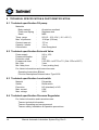
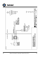
1
Turbine Gas Meter
Automatic lubrication system
INSTRUMENT INSTRUCTION MANUAL
en
Manual Automatic Lubrication System Eng. Rev.0
1
Revision History
Revision
Content of Change
Document Pages
total :
Used Signs
Sign
Description
Warning
Indicates a procedure that has to be strictly followed as
contravention may result in injury to personnel or loss of life
Caution
Highlights a procedure which, if not strictly followed , can
result in injury to personnel or damage to equipment
)
2
Note
Is an important element of the procedure and should be
observed
Manual Automatic Lubrication System Eng. Rev.0
en
Contents
1 INTRODUCTION ........................................................................................................... 6
2 GENERAL DESCRIPTION ........................................................................................... 7
2.1 Operating principle ............................................................................................... 7
2.1.1 Working principle of the oil pump...................................................................... 8
2.1.2 Flow chart of the oil pump................................................................................. 9
3 INSTALLATION .......................................................................................................... 10
3.1 Start-Up................................................................................................................ 11
4 MAINTENANCE .......................................................................................................... 12
4.1 Periodic inspections........................................................................................... 12
5 TROUBLE SHOOTING ............................................................................................... 13
5.1 Refilling the oil reservoir.................................................................................... 14
6 DISMANTLING ........................................................................................................... 14
7 FURTHER INFORMATION ......................................................................................... 15
7.1 Publications by Instromet .................................................................................. 15
7.2 International Reference Material........................................................................ 15
7.3 OIML R6, General specifications for gas volume meters ................................ 15
7.4 OIML R32, Rotary piston meters and turbine gas meters ............................... 15
7.5 AGA report No. 7, Measurement of fuel gas by turbine meters. ..................... 15
8 TECHNICAL SPECIFICATION & PART IDENTIFICATION ....................................... 16
8.1 Technical specification Oil pump ...................................................................... 16
8.2 Technical specification Solenoid Valve ............................................................ 16
8.3 Technical specification Level-switch ................................................................ 16
8.4 Technical specification Pressure Regeulator................................................... 16
9 ATTACHMENTS ......................................................................................................... 17
9.1 Reverse Contact.................................................................................................. 17
9.2 Oil Frequency ...................................................................................................... 18
Connection diagramm .............................................................................................. 19
Description Solenoid type 6106............................................................................... 21
Operrating Instructions Solenoid type 6105/6106 ................................................... 25
en
Manual Automatic Lubrication System Eng. Rev.0
3
Product information Pressure regulator type BB-1............................................... 31
9.5.1 Safety Instructions Pressure Reglator ............................................................ 32
9.5.2 Operation and Service manual Pressure regulator ........................................ 34
FIGURES
Fig. 1
Automatic Lubrication System.......................................................................... 7
Fig. 2
Pump Automatic Lubrication system ................................................................ 8
Fig. 3
Principle flow chart ........................................................................................... 9
Fig. 4
Piston check.................................................................................................... 13
Fig. 5
How to Clean.................................................................................................. 14
Fig. 6
Detail lever-switch .......................................................................................... 17
4
Manual Automatic Lubrication System Eng. Rev.0
en
In the design and construction of this equipment and
instructions contained in this manual, due consideration has been
given to safety requirements in respect of statutory industrial
regulations.
Users are reminded that these regulations similarly apply to
installation, operation and maintenance, safety being mainly
dependent upon the skill of the operator and strict supervisory
control.
en
Manual Automatic Lubrication System Eng. Rev.0
5
1 INTRODUCTION
The Instromet Turbine Gas Meter is a state of the art precision instrument,
which measures the flow of gases by means of a turbine wheel. As extension
to the known lubrication possibilities Instromet has developed an Automatic
Lubrication System. With the line pressure and an electrical signal this system
is able to lubricate the turbine gas meter independently. It will help to keep the
turbine gas meter in the optimum working condition.
The purpose of this manual is to provide a general guide to the installation,
operation and care of automatic lubrication system for turbine gas meter.
Every effort has been made to ensure that the information contained in this
manual is as accurate as possible, however, the continuous improvements
which Instromet makes to its products may result in small inconsistencies.
Custom manufactured equipment or “specials” may also result in differences.
It is highly recommended to use the Automatic lubrication system in
combination with the Instromet Smart-Index providing the required signal.
)
6
It is therefore prudent to consult the specific technical data
and other documents which accompanies the system. If in
any doubt, Instromet should be contacted.
Manual Automatic Lubrication System Eng. Rev.0
en
2 GENERAL DESCRIPTION
)
2.1
The automatic lubrication system must be considered a part
of the pressure containing system.
Operating principle
The automatic Lubrication System consists of three main parts, pressure
regulator (1), solenoid valve (2) and oil pump (3). The working principle of the
pressure regulator and solenoid valve are described in the manuals from the
suppliers, see attachments. In this part we will only describe the working
principle of the oil pump.
1
2
3
Fig. 1
Automatic Lubrication System
All other parts are described in
See attachments
en
the attached company manuals.
Manual Automatic Lubrication System Eng. Rev.0
7
2.1.1 Working principle of the oil pump
3
5
1
4
2
Fig. 2
Pump Automatic Lubrication system
The oil pump consists of two main parts, as they are pump body and the
piston assembly. This assembly consists of a pneumatic piston (2) and a
hydraulic piston (3), see figure 2. By means of the 3/2 solenoid valve channel
(1) is pressurised and de-pressurised. When pressurised the pneumatic
piston is activated its force exceeded the spring setting and pulls the hydraulic
piston into the housing. The locked quantity of lubrication in housing is
transported trough the channel (4) to the turbine gas meter. De-pressurising
the pneumatic piston will allow the spring to pull up the hydraulic piston again
allowing the pump body to re-fill again for the next stroke. In order to detect a
low oil level in the oil reservoir a low-level switch (5) is built in. This switch can
be easily changed from NO (normally open) into NC (normally closed) by
means of reverse mounting of the lever. For description see attachment
Reverse Contact
8
Manual Automatic Lubrication System Eng. Rev.0
en
2.1.2 Flow chart of the oil pump
1
2
3
4
5
Fig. 3
Index
Pressure tapping point
Pressure regulator
Safety valve
Solenoid valve
Oil pump
Principle flow chart
From the pressure tapping point the gas or compressed air is lead to the
pressure regulator which is reducing the (line) pressure 7 upto 130 bar to 6
bar. An additional safety relief valve (3) is build in to protect the system. This
relieve valve is be connected with the open air in case the line pressure is
used. The solenoid valve (4) is also equipped with a button to allow manual
lubrication. With this button the pump can be tested also.
en
Manual Automatic Lubrication System Eng. Rev.0
9
3 INSTALLATION
Installation only by authorised skilled people.
International, national, local and company safety rules are
to be strictly followed as contravention may result in injury
to personnel or loss of life.
Factory settings of pressure regulator and pressure relieve
valve are not to be changed.
Recommended way of connecting to a turbine gas meter is described in
Technical Note TN-11.368
If the meter is located in a zone classified as hazardous, all
connections must be to intrinsically safe circuits.
Connect the (line) pressure or compressed air to the pressure regulator inlet
marked with “in”.
Verify if the outlet pressure from the regulator is
appropriate to the intended application.
Fill the oil reservoir with the oil delivered with the turbine gas meter.
The oil should be clean and free of liquids, dust or foreign
material, which could damage the automatic lubrication
system.
10
Manual Automatic Lubrication System Eng. Rev.0
en
3.1 Start-Up
At the first use external oil pipes has to be filled-up with oil. This has to be
done by a predicted number of manual strokes using the button on the
solenoid.
Each push is one stroke.
In order to estimate the required number of strokes the equation below can be
used.
Number lubrications = ( L / 8 ) + V
Where:
L = the length of the external oil piping in cm
V = additional volume inside meter body as a factor depending on size
Size
V
50 / 2”
1
80 / 3”
1
100 / 4”
3
150 / 6”
4
200 / 8”
4
250 / 10”
7
300 / 12”
8
400 / 16”
10
500 / 20”
12
600 / 24”
14
Lubricate the turbine gas meter with the required strokes by pushing the red
button on the solenoid valve and checking the hydraulic piston is moving at
each strokes.
Close the oil reservoir.
Adjust the right lubrication frequency at the Smart-Index. See manual Smart
Index. Lubrication frequency for normal use is given in attachment Oil
Frequency
en
Manual Automatic Lubrication System Eng. Rev.0
11
4
MAINTENANCE
It is not allowed to carry out any repair or maintenance
during use.
The turbine gas meter operates under pressure and / or at dangerous
mediums.
The turbine gas meter can be in operation at high or low
temperature.
Due to this fact the turbine gas meter can turn very hot or cold and touching
can cause serious injuries.
4.1 Periodic inspections
No inspection (of the lubrication system) can be done while
the system is activated.
The gas stream should be clean and free of liquids, dust or
foreign material, which could damage the meter rotor and
mechanism.
A correct functioning of the piston can be
checked by measuring “L”, with a clean
slide gauge, the distance between
hydraulic piston and the top of the oil
reservoir, see figure 4
Fig. 4
12
Piston check
Manual Automatic Lubrication System Eng. Rev.0
en
Operate button manual and measure the distance L again. The difference
between the two measurements must be 26 ±1 mm. If the distance is less the
system is not working correct and needs maintenance.
5 TROUBLE SHOOTING
No inspection and or maintenance (of the lubrication
system) can be done while the system is activated.
Check the working pressure of the automactic lubrication system. This is the
outlet pressure of the pressure regulator it must 6 bar. Measure the distance
L again as described above.
If the required distance is not achieved the cilinder inside (1) has to be
cleaned and greased again. Remove cable gland (2) from oil-level switch,
untight 4 crews (3) and remove the bottom, see figure 5.
1
3
2
4
Fig. 5
How to Clean
Clean the cilinder inside and grease with Molykote 55M or equal.
Mount all parts and perform 10 manual strokes. At the last stroke the distance
L should measured again. If the distance L is still to smal the “back” pressure
from the turbine gas meter may be to high. This is to verify by removing the oil
pipe (4) at the bottom side of the lubrication system see figure 5. Please
collect the released oil and discharge it in the correct way.
en
Manual Automatic Lubrication System Eng. Rev.0
13
Perform a manual stroke again and measure the distance L again. If the
distance is correct the check valve of the turbine gas meter is the problem.
Otherwise the automatic lubrication system is defect.
5.1 Refilling the oil reservoir
The oil reservoir has to checked and refilled regularly. See attachment 9.2
Before refilling verify the remaining oil is clean. If not, the remaining oil should
be discharged in a proper way. To discharge the remaining oil the drain at
the bottom of the oil reservoir can be opened or the pump has to be
dismantled.
6 DISMANTLING
Before a meter may be dismantled or removed from the
installation, the line must be de-pressurised.
It is important that the line is de-pressurised slowly and
with care to prevent damage to the turbine and bearings.
See manual turbine gas meter
The measuring line should be at ambient temperature before the gas meter is
removed.
The oil reservoir has to checked and the remaining oil should discharged on a
proper way. To discharge the remaining oil the drain at the bottom of the oil
reservoir can be opened or the pump has to be dismantled
Dismantling the pump by:
Remove (line) pressure or compressed air from the system
Remove the pressure connection
Remove the electrical connection
Dis-assamble the pump from the turbine gas meter by removing the 2 M8
bolts
Remove the remaining oil from the reservoir and discharge it on a proper way
14
Manual Automatic Lubrication System Eng. Rev.0
en
7 FURTHER INFORMATION
7.1 Publications by Instromet
Turbine Gas Meter Handbook
P-Meter Handbook: Turbine Meters for Ethylene
7.2 International Reference Material
International standards:
ISO 9951: 1993,
Measurement of gas flow in closed conduits – Turbine meters.
Recommendations of the International Organisation of Legal Metrology:
7.3 OIML R6, General specifications for gas volume meters
7.4 OIML R32, Rotary piston meters and turbine gas meters
American Gas Association:
7.5 AGA report No. 7, Measurement of fuel gas by turbine meters.
en
Manual Automatic Lubrication System Eng. Rev.0
15
8 TECHNICAL SPECIFICATION & PART IDENTIFICATION
8.1 Technical specification Oil pump
Materials
Body material
Piston and Spring
Seals
Temp. range
Max. oil pressure
Content reservoir
Capacity / stroke
Connecetion
:
:
:
Aluminium anodized
Stainless steel
NBR
:
:
:
:
:
263.15 – 333.15 K ( -10 / +60° C)
10 M pa (100 bar)
175 cc
1.5 cc
6mm Swagelock
8.2 Technical specification Solenoid Valve
Power supply
Powerconsumption
Protection class
Ex approval class
Min. puls
Min. delay time
:
:
:
:
:
:
24V ± 10%
0.5 W
IP65
II 2G EEx ia IICT5 or T6 ( Old - EEx ia IIC6T)
3 sec
5 sec (resting time)
For furhter informations and instructions see:
Operating Instructions Bürkert
Function descriptions Solenoid valve Type 6106
8.3 Technical specification Level-switch
Material
Switch
Execution
Max. current
Max. voltage
:
:
:
:
:
Polyamide
Reed switch
NC (standard) or NO
0.5A
200V
8.4 Technical specification Pressure Regeulator
For further information and instructions see:
Tescom technical information
Tescom Operatiing and servicemanual
Tescom safety, Installation & Operation precautions
16
Manual Automatic Lubrication System Eng. Rev.0
en
9 ATTACHMENTS
9.1 Reverse Contact
If required the oil-level switch, which is Normaly Open, can be changed into
Normaly Closed version.
Fig. 6
en
Detail lever-switch
-
Prepare your tools to be clean
-
Open the reservoir by removing the reservoir cap.
-
Remove ring (1) figure 7
-
Take the level-body (2) from the pilar
-
Place the level-body upside down
-
Replace ring (1)
-
Test the sensor
-
Close the reservoir with the cap again
Manual Automatic Lubrication System Eng. Rev.0
17
9.2 Oil Frequency
Lubricating frequency of Instromet trubine gas meters
Size
50 / 2”
80 / 3”
100 / 4”
150 / 6”
200 / 8”
250 / 10”
300 / 12”
400 / 16”
500 / 20”
600 / 24”
18
Lubricatio 1 x
per …. Days
60
60
60
60
60
60
60
60
60
60
Lubrication
quantity (cc)
1.5
3
3
4.5
4.5
7.5
7.5
9
12
12
Reservoir
refill
1x per …. year
5
5
5
5
5
3
3
3
2
2
Manual Automatic Lubrication System Eng. Rev.0
en
9.3 Connection diagramm
en
Manual Automatic Lubrication System Eng. Rev.0
19
20
Manual Automatic Lubrication System Eng. Rev.0
en
9.4 Description Solenoid type 6106
22
Manual Automatic Lubrication System Eng. Rev.0
en
en
Manual Automatic Lubrication System Eng. Rev.0
23
24
Manual Automatic Lubrication System Eng. Rev.0
en
en
Manual Automatic Lubrication System Eng. Rev.0
25
9.4.1 Operrating Instructions Solenoid type 6105/6106
26
Manual Automatic Lubrication System Eng. Rev.0
en
en
Manual Automatic Lubrication System Eng. Rev.0
27
28
Manual Automatic Lubrication System Eng. Rev.0
en
en
Manual Automatic Lubrication System Eng. Rev.0
29
30
Manual Automatic Lubrication System Eng. Rev.0
en
en
Manual Automatic Lubrication System Eng. Rev.0
31
9.5 Product information Pressure regulator type BB-1
32
Manual Automatic Lubrication System Eng. Rev.0
en
9.5.1 Safety Instructions Pressure Reglator
en
Manual Automatic Lubrication System Eng. Rev.0
33
9.5.2 Operation and Service manual Pressure regulator
34
Manual Automatic Lubrication System Eng. Rev.0
en
9.5.3 Operation and Service manual pressure regulator
en
Manual Automatic Lubrication System Eng. Rev.0
35
36
Manual Automatic Lubrication System Eng. Rev.0
en