1
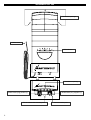
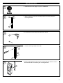
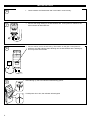
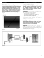
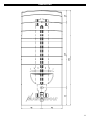
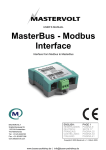
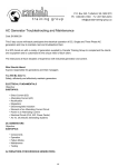
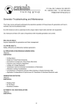
USER’S MANUAL
Windmaster 500
Grid connected wind inverter
This product must be protected externally against over voltages that may occur in noload and / or extreme wind conditions. Exceeding the specified maximum input
voltage must be avoided under any circumstances. Most turbine manufacturers
supply a protection circuit to protect power converters from these conditions. Failure
to do so may cause serious damage to the inverter and will void product warranty.
MASTERVOLT
Snijdersbergweg 93, 1105 AN Amsterdam
The Netherlands
Tel.: +31-20-342 21 00
Fax: +31-20-697 10 06
www.mastervolt.com
v 1.0 December 2006
WINDMASTER 500
Ventilation openings
Mains cord
LED indicator
Ventilation opening
MultiContact plug positive (+)
Tab to release the mounting lock
2
MultiContact plug negative (–)
Communication port
INSTALLATION
• Read instructions on page 5 -8 prior to installation.
1
2
• Mark the position of the two mounting spots A and B by using the
mounting bracket
A
B
• If necessary, drill mounting holes at spots A and B
3
A
B
• Fix the mounting bracket to the wall
4
A
B
5
• Place the Windmaster 500 over the mounting bracket and then move it
downwards until it is locked by the mounting bracket
3
INSTALLATION
•
6
Check whether the Windmaster 500 is mounted in a secure way.
• Connect the string cabling to the Windmaster 500. If wind power is sufficient, the
LED indicator will illuminate red.
7
+
–
• Connect mains cord to the AC-wiring. Then switch on the grid. If wind power is
sufficient, the LED-indicator starts blinking red: the Windmaster 500 is starting up.
This may last a few seconds
8
AC
9
• After starting up, the LED-indicator starts blinking yellow.
• If wind power is too low, the indicator will extinguish
4
ENGLISH
Product description and application
Congratulations for choosing the Mastervolt
Windmaster 500. The Windmaster 500 is a inverter
for grid connection of small wind turbines. The
design is based on the successful Soladin 600 Solar
inverter. Windmaster 500 is an “OEM” product and
is sold as a part of a system through selected
system vendor. The product is to be installed only
with selected wind turbines. A system is evaluation
by Mastervolt is part of the qualification process.
Unpacking
The delivery consists of the following parts:
• The Windmaster 500 with mounting bracket
• This user’s manual
• MultiContact “Pigtail” adapters (2x)
• Windmaster 500 PC-Link
After unpacking, check the Windmaster 500 for
possible damage. Do not use the Windmaster 500 if
it is damaged. If in doubt, contact your system
vendor.
USERS MANUAL WINDMASTER 500
Safety
Max Input Voltage
Max Input Current
Nom Input Power
Max Short Circuit
150V
8A
550Wdc
12A
• Contact an installer if the wind system does not
comply with the above mentioned stipulations.
Due to possible high voltages installation and
modification may only be carried out by a
qualified electrician who is familiar applicable
regulations and standards.
• Install the Windmaster 500 according to the
instructions stated in this manual.
• Be sure that the Windmaster 500 is disconnected
from the grid during installation. This can be done
by removing the fuse of the corresponding
branch circuit at the AC distribution board
• Connections and safety features must be
executed according to the locally applicable
regulations
• The Windmaster 500 must be used in
accordance with the specifications as stated on
page 10
• Never open the housing as high voltages may be
present inside!
5
USERS MANUAL WINDMASTER 500
ENGLISH
Choosing the location to install
Obey the following stipulations during installation:
Directions for installation
The Windmaster 500 is equipped with a so called
“anti-islanding safety device”. It ensures immediate
switch off in case of grid failure. European countries
maintain different regulations with regard to antiislanding devices and the supply of energy back to
the utility grid in general.
• The Windmaster 500 is suited for indoor use
only.
• Ambient temperature: -20 ... 50°C; (power
derating above 40°C), Humidity: 0-90% non
condensing
• Choose a optimal location to avoid long DC and /
or AC wiring to minimize loses.
• Do not install the Windmaster 500 in
environments with heavy dust development or
humidity.
• If the Windmaster 500 is installed in the
immediate vicinity of living areas, take into
account that it produces a slight noise level when
operating.
• Mount the Windmaster 500 vertically on a solid,
non-resonating, wall.
• Mount the Windmaster 500 in such a way that
obstruction of the airflow through the ventilation
openings is prevented
• No objects must be located within a distance of
20 cm around the Windmaster 500.
• Multiple Windmaster 500 may be mounted next
to each other, not above each other. Minimum
spacing: 20 cm.
Things you need to install the Windmaster 500
Make sure you have all the parts you need to install
the Windmaster 500:
• The Windmaster 500
• Two screws (with plugs) to mount the
Windmaster 500. Maximum diameter: 4.5 mm.
Use mounting materials which are suitable to
carry the weight of the Windmaster 500.
• Tools to fix the screws / bolts with plugs into the
wall (screwdriver, drilling machine, a set of drills,
a pencil)
6
In some countries one single Windmaster 500 may
be connected to an existing electricity branch circuit
which is fused with 16 Amp. In other countries
different restrictions apply. Please acquaint yourself
with the local regulations on this issue!
The Windmaster 500 is sold as a part of a system.
Your system vendor will provide the Windmaster
500 with the appropriate settings for the local
electrical grid. Never connect the Windmaster 500
to a utility grid which is not suitable for use with the
apparatus!
During installation you can check by means of the
LED-indicator whether the installation is done
properly. This check can only be carried out when
sufficient wind power is present.
Although the Windmaster 500 is protected against
wrong polarity, the positive (+) and negative (–) of
the wind turbine connections should not be
exchanged.
Install the product according to the instructions
stated on page 3 and 4.
Monitoring
The Windmaster 500 has a communication port that
can be connected to the COM-port (RS232) of a PC
or laptop. Use the provided “Mastervolt PC–link”
interface and cable to set up a connection.
Part number
130391030
Description
PC-link Soladin/Windmaster,
incl. communication cable, 2m
NOTE: Communication is only possible
when sufficient wind power is present.
ENGLISH
USERS MANUAL WINDMASTER 500
LED indicator
The operation mode of the Windmaster 500 is
displayed by means of a LED indicator at the front
side of the housing. In normal operation it flashes
yellow: the faster the LED blinks yellow, the more
power is converted.
If the energy of the wind turbine is insufficient, the
Windmaster 500 switches off automatically. When
switched off, the LED indicator is off.
Indication of the LED
LED is off
Meaning
Insufficient wind
power
No power from the
wind turbine
LED is off
• • • • •
Yellow blinking
▬
▬
▬
Slow blinking long red
pulses
▬▬▬▬▬▬
Fast blinking long red
pulses
▬▬▬▬▬▬▬▬
Uninterrupted red
• • • • •
Red blinking 1 time
Normal operation
•• •• •• ••
Red blinking 2 times
••• ••• •••
Red blinking 3 times
•••• ••••
Red blinking 4 times
••••• •••••
Red blinking 5 times
••••••
Red blinking 6 times
Turbine voltage too
high
AC grid voltage too
high
AC grid voltage too
low
Grid frequency too
high or too low
Internal temperature
too high
•••••••
Red blinking 7 times
NTC error
Reclosure time
Restart time lag
No grid voltage
Turbine voltage too
low
Failures
As long as the indication LED isn’t illuminated red,
no failure is detected: the Windmaster 500 is
operating normally. If an error occurs, it is detected
by the apparatus itself: the LED indicator turns red.
Consult the vendor, if you cannot solve the problem
by means of the table below.
NOTE: during low wind trubine voltage
detected by the Windmaster 500, indicated
by a red blinking LED indicator. This is a
normal situation
What to do?
Nothing. The Windmaster 500 operates normally, but power coming
from the wind turbine is insufficient
Consult an installer if the LED indicator is off while wind power is
sufficient. The wiring between the wind turbine and the Windmaster
500 might be defective. Check for loose connections or incorrect
polarity.
Nothing. The Windmaster 500 operates normally. The faster the LED
blinks yellow, the more power is converted.
Nothing. After the Windmaster 500 was (re)connected to the AC grid,
it checks the quality of the AC grid before it starts operating normally.
This may take up to 5 minutes.
Nothing. A system check is carried out during startup. This may take
up to 5 seconds before the Windmaster 500 starts operating
normally.
Plug the AC-plug of the Windmaster 500 into the wall socket; check
the fuse in the meter cupboard.
Nothing; normal condition during low wind conditions.
Consult an installer if the problem remains while a strong wind
conditions exists.
Error in the Wind turbine system. Is the wind turbine qualified for use
in accordance with Windmaster 500?
Consult an installer. Error in the installation. Is the wind turbine
qualified for use in accordance with Windmaster 500?
Check the grid connection.
Check the grid connection.
Check the grid connection.
Air flow of the Windmaster 500 may not be obstructed. If the problem
remains, switch off the Windmaster 500 by removing the fuse from
the meter cupboard and consult your system vendor.
Consult your system vendor for repair of a defective safety device in
the Windmaster 500.
7
USERS MANUAL WINDMASTER 500
Operation
After installation the Windmaster 500 will switch on
automatically if wind power is sufficient. The
Windmaster 500 operates automatically: there is no
need for user adjustment or control. The
Windmaster 500 has no ON/OFF switch; If
necessary remove the fuse from the AC distribution
board to switch it off. Do not disconnect the
MultiContact plugs during operation of the
Windmaster 500! No specific maintenance is
required. If necessary, use a soft clean cloth to
clean the Windmaster 500. Never use any liquids,
acids and/or scourers.
Decommissioning
First remove the Fuse from the AC distribution
board before you disconnect the MultiContact plugs.
Now the Windmaster 500 can be demounted in a
safe way:
1. Push on the lower tab of the mounting bracket to
release the mounting lock.
2. Lift the Windmaster 500 upwards for
approximately 1 cm.
3. Move the Windmaster 500 straight from the wall
8
ENGLISH
Warranty and Support
The inverter is supplied with a 2-year standard
product warranty. Other warranty agreements
between system vendor and Mastervolt may apply.
First line service and support is performed by the
system vendor. Defects caused by DC or AC over
voltage, out-of-specification short circuit current,
direct or induced lightning and surges as well as
cost of travel, installation and energy loss are
excluded from product warranty.
Liability
Mastervolt cannot be held liable for:
• Possible errors in this included manual and the
consequences of these.
• Use that is inconsistent with the purpose of the
product.
ENGLISH
USERS MANUAL WINDMASTER 500
Power Curve
The Windmaster 500 converts DC power from a
wind turbine to the AC grid based. This conversion
is based upon a linear curve with a start voltage and
a maximum operating voltage (see figure 1). These
parameters may be adjusted and optimized by the
system vendor for use with a particular wind turbine.
When DC voltage reaches the threshold voltage to
start up the Windmaster, the inverter starts a 5
seconds countdown before delivering energy to the
AC grid.
Pdc [W]
550
500
Example installation diagram
See figure 2. This drawing is not specific for any
wind turbine or installation. It is provided as a basic
reference, showing necessary major components
and installation sequence. Please contact your
system vendor for detailed installation drawings,
specific for you wind turbine.
DC interface
The DC interface is for protection of the Windmaster
500, and should provide the following.
• Surge protection (if applicable)
• Over voltage protection, max. 150VDC (*)
• Disconnection switch (if applicable)
(*) Mechanical either electrical OVP may be
integrated in the wind turbine
450
400
Grounding
The Windmaster 500 is a class II device with
galvanic isolation between DC and AC. The inverter
doesn’t need to be grounded. Grounding of the
Wind turbine however is recommended.
350
300
250
200
150
100
50
10 20 30 40 50 60 70 80 90 100 110 120 130 140150
Udc [V]
Paralleling
Multiple Windmasters 500 can be operated in
parallel to increase output power. The DC-side of
each Windmaster 500 must be protected by a 10A
(slow blow) fuse (refer to fig. 2).
Figure 1
Figure 2
9
SPECIFICATIONS
Model
Part number:
Manufacturer:
Operating temperature:
Storage temperature:
Relative humidity:
Protection degree:
Safety class:
Galvanic isolation
Dimensions (H x W x D):
Weight:
Enclosure:
Mounting
Windmaster 500
140000500
Mastervolt, Amsterdam, the Netherlands
-20°C to 50°C (full power up to 40°C)
-20°C to 70°C
Max. 95%, non condensing (electronics have anti-moisture coating)
IP23 (for indoor use)
Class II Double insulated
Class II HF transformer
365 x 143 x 75 mm
Approx. 2 kg.
UL 5V fire retardant ABS/PC
Wall mounting bracket included
Input (DC)
Nominal power:
Operating voltage range:
Full power voltage range:
Max current:
Max short current:
Start-up power:
Connectors:
550WDC
35-150 VDC
65-125 VDC
8A
12A
1W
MultiContact 4mm type connectors ; adapters are included
Paralleling
Multiple units can be operated in parallel to increase output power
The DC-input of each unit must be protected by a 10A DC (slow blow) fuse
Output
Voltage:
Nominal power:
Nominal current:
Fuse:
Frequency:
Cos phi:
Stand-by power:
Maximum efficiency:
Mains cord:
230V (185V-264V)
525W
2,25A
3,15A -T
50 Hz (48-52 Hz)
0,99
< 0,05Wac
93%
1,8 meter of AC wire
Safety Functions
Anti-Islanding
Over temperature
Polarity
Surges
Voltage- and frequency window; frequency shift G83 compliant
Power derating at > 40 °C; switch off at internal over temperature
Protected against inverse polarity
Protected against AC and DC surges caused by indirect lightning strike
User Interface
Front indicator
Normal operation
Fault indication
Communication
Dual color (yellow/red)
Yellow blinking (faster blinking = higher power)
Red flashing (6 different codes)
PC-Link adapter and cable for RS-232 communication included. PC software
downloadable from www.mastervolt.com
National grid connection regulations
Approvals:
G83 (GB); NTA 8493 (Netherlands)
Country compatibility
Standard suitable for all 230V / 50 HZ countries. Country specific settings
programmable. External ENS may be required for some countries
(contact your local distribution network operator for local grid connection)
requirements)
10
40
350
245
65
DIMENSIONS
11
CE DECLARATION OF CONFIRMITY
Manufacturer: Mastervolt
Address:
Snijdersbergweg 93
1105 AN Amsterdam
The Netherlands
Herewith declares that:
Product:
Windmaster 500
Is CE-marked and complies with the following standards:
EMC directive
Environment:
89/336/EEC
residential, commercial and light industrial
Emission
Emission - class B:
harmonic current emission:
EN 55022: 1998
EN 61000-3-2: 2000
Immunity
Generic immunity standard:
Electrostatic discharge (ESD):
Radiated EMC:
Electrical fast transients (EFT) :
Surge transient :
Conducted RF disturbances :
Voltage dips and short interrupts :
Digital radio telephones :
EN 61000-6-2: 2001
EN 61000-4-2: 1995
EN 61000-4-3: 1996
EN 61000-4-4: 1995
EN 61000-4-5: 1995
EN 61000-4-6: 1996
EN 61000-4-11: 1994
ENV 50204: 1995
Safety
Low Voltage directive :
Electrical safety :
LV 73/23 EEC
EN 60950 : 2003
Amsterdam,
R.J. ter Heide,
General Manager MASTERVOLT
12
© Mastervolt BV, Snijdersbergweg 93, 1105 AN Amsterdam, Netherlands
Tel: + 31-20-3422100 Fax: + 31-20-6971006 Email: [email protected]