1
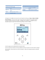
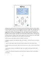
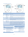
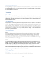
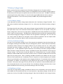
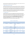
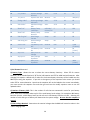
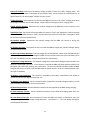
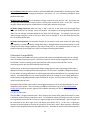
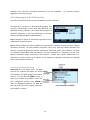
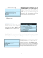
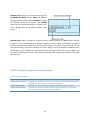
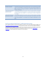
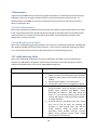
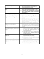
Pika B801 REcharge™
Off-grid Charge Controller
Operation Manual
Operation Manual B801 Bidirectional REbus™ Battery Charge Controller
Revision Table
Revision
Date
Changes
1.0
03/19/2015
Initial Release
General Remarks
Congratulations! You have purchased the Pika Energy B801 Bidirectional REbus™ Charge Controller, a
dependable, efficient component of your clean energy system. The B801 is the result of the Pika team’s careful development and testing, building on decades of experience in the fields of power electronics
and renewable energy systems.
The B801 is a charge controller designed for high-efficiency bidirectional conversion between a REbus™ Microgrid and a 24V to 48V battery bank. This charge controller is equipped with a small fan to keep
things cool under extreme conditions. An illuminated display and intuitive system of menus enable you
to configure a variety of setpoints as well as view the energy output of every component of your
renewable energy system. The charge controller also serves as an information gateway, enabling
monitoring and control of your entire renewable energy system.
Unlike conventional charge controllers, which only connect to one type of energy source, Pika’s B801 is designed to operate as the hub for an expandable network of renewable energy devices, based on the
REbusTM renewable energy standard.
What is REbusTM?
The underlying technology behind Pika’s B801 charge controller is an innovative energy management
technology or ‘smart microgrid’ called REbus™. REbus™ is a DC energy network that enables customers
to build cost-effective, scalable renewable energy systems. The REbusTM network is designed to serve as
an open interconnection standard for networking next-generation energy technology – like Wi-Fi or USB
for green energy!
IMPORTANT! Only REbusTM compatible components may be used in connection with this charge
controller. Do not connect the output of a PV array or any other non-REbusTM electrical source to the
charge controller terminals. Serious property damage and/or personal injury may result.
1
Contents
Revision Table ............................................................................................................................................... 0
General Remarks ........................................................................................................................................... 1
1 Regarding this Document ......................................................................................................................... 4
1.1 Symbols used in this document .......................................................................................................... 4
1.2 Data Label ........................................................................................................................................... 4
2 Important safety information and instructions ......................................................................................... 5
2.1 Appropriate Usage .............................................................................................................................. 5
2.2 Supported Battery Types .................................................................................................................... 5
3 Notes concerning installation and operation ............................................................................................ 6
3.1 Intended (normal) use ........................................................................................................................ 6
3.2 Pika Energy Factory Limited Warranty................................................................................................ 6
3.3 Service ................................................................................................................................................. 6
4 The REbusTM Microgrid............................................................................................................................... 7
4.1 Simple and Efficient Power Distribution and Management ............................................................... 7
4.2 Integrated Power Line Carrier (PLC) Communications ....................................................................... 7
4.3 REbus™ Control Protocol (RCP)........................................................................................................... 7
5 Designing a REbus™ System ....................................................................................................................... 8
6. User Interface............................................................................................................................................ 8
6.1 Overview of User Interface ................................................................................................................. 8
6.2 LED Displays ........................................................................................................................................ 8
6.2.1 Multicolor “REbus™” LED ............................................................................................................. 8
6.2.2 Multicolor “Battery” LED ............................................................................................................. 8
6.2.3 Blue “Wi-Fi” LED ........................................................................................................................... 9
6.3 LCD Display .......................................................................................................................................... 9
6.3.1 REbus™ System Page.................................................................................................................... 9
6.3.2 B801 Charge Controller Page ..................................................................................................... 10
6.3.3 Wi-Fi Status Page ....................................................................................................................... 14
6.3.4 Other REbus™ Device Pages ...................................................................................................... 15
6.3.5 Background Illumination ............................................................................................................ 16
7 Operation ................................................................................................................................................. 16
2
7.1 Installation ........................................................................................................................................ 16
7.2 Power Switch .................................................................................................................................... 16
7.3 Enable/Disable .................................................................................................................................. 16
7.4 Charging Stages ................................................................................................................................. 16
7.4.1 Terms ......................................................................................................................................... 16
7.4.2 Bulk............................................................................................................................................. 17
7.4.3 Absorption.................................................................................................................................. 17
7.4.4 Float ........................................................................................................................................... 17
7.4.5 Equalize ...................................................................................................................................... 17
7.5 Battery Voltage Limits ....................................................................................................................... 18
7.5.1 Low Battery Voltage ................................................................................................................... 18
7.5.2 Error Low Battery Voltage .......................................................................................................... 18
7.5.3 High Battery Voltage .................................................................................................................. 18
7.6 High Temperature Operation............................................................................................................ 19
7.7 Configurations ................................................................................................................................... 19
8 Internet Compatibility .............................................................................................................................. 22
8.1 Wi-Fi Antenna ................................................................................................................................... 22
8.2 Configuring your Wi-Fi Connection ................................................................................................... 23
8.2.1 Scan-based network setup ......................................................................................................... 23
8.2.2 Add network setup..................................................................................................................... 24
8.3 Wi-Fi Status Messages and Troubleshooting .................................................................................... 25
8.3.1 Connection states: ..................................................................................................................... 25
8.3.2 Connection state messages: ...................................................................................................... 26
8.4 Pika account and the REview™ online monitoring system ............................................................... 27
9 Maintenance ............................................................................................................................................ 28
9.1 Battery Maintenance ........................................................................................................................ 28
9.2 Handling Errors and Faults ................................................................................................................ 28
10 Troubleshooting Guide .......................................................................................................................... 28
11 Frequently Asked Questions .................................................................................................................. 30
12 Specifications ......................................................................................................................................... 31
3
1 Regarding this Document
This manual contains important instructions for the B801 Charge controller that must be followed during
installation and maintenance of the charge controller. The B801 is designed with safety in mind, but as
with all electrical and electronic equipment, certain precautions must be observed when installing
and/or operating the B801. To reduce the risk of personal injury and to ensure the safe installation and
operation of the B801, you must carefully read and follow all instructions, cautions and warnings in this
user manual.
Store this manual so that it is always easily accessible.
1.1 Symbols used in this document
WARNING: This indicates a fact or feature very important for the safety of the user to
prevent injury or death and/or which can cause serious hardware damage if not
applied appropriately.
CAUTION: Presents information to prevent damage to this product
EARTH GROUND SYMBOL
1.2 Data Label
A permanently affixed label indicating the device specifications, serial number, and manufacturing date
is located on the bottom surface of the charge controller enclosure. Tampering with the label can void
warranty.
4
2 Important safety information and instructions
IMPORTANT SAFETY INSTRUCTIONS
SAVE THESE INSTRUCTIONS
This manual contains important instructions for model B801 that shall be followed during installation
and maintenance of the Pika B801 Charge controller.
WARNING: Before installing the Pika Energy B801 Charge controller, read all instructions and
caution markings in this manual and on the B801 as well as on other REbus™ devices. WARNING: Electrical installation in the United States shall be done in accordance with all local
electrical codes and/or the National Electrical Code (NEC), ANSI/NFPA 70.
WARNING: Electrical installation in Canada shall be done in accordance with all local electrical
codes and/or the Canadian Electrical Code.
2.1 Appropriate Usage
The B801 is a charge controller designed for high-efficiency bidirectional conversion between a REbus™ DC Microgrid and a 24V to 48V battery bank. Refer to the charge controller installation manual for
detailed information about the product and its intended use. The charge controller may only be
operated with REbus™ devices. Do not use the charge controller for purposes other than those
described here. Alternative uses, modifications to the charge controller or the installation of
components not expressly recommended or sold by the manufacturer void the warranty claims and
operating permission. Contact Pika Energy technical support if you need clarification regarding proper
use of the charge controller.
2.2 Supported Battery Types
The B801 is to be connected to a 24V to 48V battery bank, contact Pika support for information
regarding other battery voltages. Supported battery chemistries include: flooded lead acid, sealed lead
acid (“maintenance free”), AGM, NiFe (Nickel-Iron), aqueous hybrid ion and lithium based chemistries.
Lithium-based chemistries including Li-ion, lithium polymer and lithium-iron phosphate may require
individual balancer circuits and special setpoint adjustments. Contact Pika Energy before using the B801
with Lithium-based battery chemistries.
5
3 Notes concerning installation and operation
3.1 Intended (normal) use
Your charge controller is strictly constructed according to approved safety requirements. Improper use
may lead to lethal hazards for operators and/or damage to devices and property. Improper use or
modification of the B801 may result in serious property damage, personal injury or death.
REBUS™ INPUT ONLY! The B801 is designed to accept regulated direct current (DC) from REbusTMcompatible devices (e.g. REbusTM-compatible wind turbine, REbusTM-compatible PV Link unit). DO NOT
CONNECT PHOTOVOLTAIC MODULES DIRECTLY TO THE REBUS™ INPUTS OF THE B801 CHARGE
CONTROLLER. DOING SO WILL VOID THE WARRANTY AND MAY DAMAGE THE CHARGE CONTROLLER.
Any use other than the specified intended use shall not be deemed intended or normal use, and may
result in property damage, personal injury or death. Pika is not liable for damage or injuries caused by
unintended use.
Damage caused by unintended use is at the sole risk of the operator.
“Intended use” shall also include adherence to the operating and installation instructions.
Your trained and authorized installer must obtain all necessary permits and agreements from your local
government and your utility company for a legal and code-compliant installation of your REbus™ Smart Microgrid system. See the User Manual for more detail.
3.2 Pika Energy Factory Limited Warranty
The Pika limited warranty covers defects in workmanship and materials of the Pika B801 Charge
Controller for a period of five (5) years from the date of original purchase of such charge controller at
point of sale to the originally-installed end user location. Contact Pika Energy Support for warranty
claim information.
3.3 Service
WARNING: Do not attempt to repair the B801 Charge Controller. The charge controller contains
no user-serviceable parts.
If the Pika B801 malfunctions or fails in any way, first contact Pika customer service at 1 (207) 887-9105
for troubleshooting help. See the Warranty section for details on terms and conditions for repair or
replacement under warranty. You must obtain an RMA (Returned Merchandise Authorization) number
prior to returning the unit. Obtain the assistance of a skilled and qualified installer to safely disconnect
the charge controller for shipment.
Technical Support Information:
Support department hours: 9AM to 5PM EST, Monday – Friday (excluding holidays)
Phone: 1-(207)-887-9105 United States Language: English
Email: [email protected]
6
4 The REbusTM Microgrid
The REbusTM Microgrid is the underlying technology that allows for the efficient and robust
interconnection of different types of renewable energy products. This section is informational only and
not required knowledge for operation of your Pika B801 Charge controller.
4.1 Simple and Efficient Power Distribution and Management
The REbusTM Microgrid architecture was designed with renewable energy in mind. A clean-sheet
approach to power distribution resulted in the most practical and efficient interconnection technology
available. The REbusTM Microgrid operates at variable voltage in a defined band, between +/- 180-200 V
relative to ground which simultaneously allows for efficient power transmission, reduced shock hazard,
and simplified electronics for a bidirectional converter such as the B801. The variable voltage
communicates energy availability to the attached REbus™ devices, which allows for prioritized energy
storage and load shedding. The REbusTM Microgrid is designed to support many different types of
renewable energy sources and power converters, as well as accommodating future 380VDC REbusTM
Microgrid loads that are presently in development.
4.2 Integrated Power Line Carrier (PLC) Communications
The REbus™ Microgrid standard also specifies an optional power line carrier communication technology
that enables devices on the same REbus™ Microgrid to communicate with one another. The B801 uses
this capability to gather information about your system such as the status and energy production of your
Pika T701 Wind Turbine or your solar array, which connects to the REbus™ Microgrid through the Pika
S2001 PV Link.
4.3 REbus™ Control Protocol (RCP)
REbus™ Control Protocol (RCP) is a communications protocol developed specifically for the transfer of
data between REbus™-compatible power converters and data management products. RCP is an openstandard protocol which enables independent developers to interface with REbus™ products and create
software and applications to enhance user experience. Please visit the Pika Energy website to learn
more about RCP and the software applications that are currently available.
7
5 Designing a REbus™ System
Your trained and qualified installer will work with the Pika Energy technical support team to design the
right system for your site. Please consult with Pika Energy sales department at (207) 887-9105 or on the
web at http://www.pika-energy.com to find an installer near you.
The Pika Energy product system is designed from the ground up for unmatched flexibility. First and
foremost, the B801 Charge controller accepts input from any combination of REbus™-compatible
sources. In fact, the B801 supports up to 32 devices on the REbus™ Microgrid network, and the
automatic power management capability of REbus™ ensures that excess input power from renewable
sources such as the Pika T701 Wind Turbine or Pika S2001 PV Link will be throttled back to prevent
over-charging of the batteries. As of publication, Pika Energy offers the following REbus™ products in addition to the B801 Charge Controller:
T701 Wind Turbine
S2001 PV Link
X3001 Inverter
REport Data Monitor
Check the Pika Energy website at http://www.pika-energy.com for the latest selection of REbus™ compatible product offerings.
6. User Interface
6.1 Overview of User Interface
The B801 Charge Controller user interface is accessible via the LCD on the front cover. It is designed to
provide basic information such as power, energy and battery voltage. Adjustable setpoints for the B801
and attached REbusTM devices can be changed from the LCD screen as well.
6.2 LED Displays
The B801 user interface is equipped with three LEDs to quickly offer information about the status of the
charge controller and other REbusTM devices.
6.2.1 Multicolor “REbus™” LED
This green/yellow/red LED indicates the status of the REbus™ microgrid and attached devices. When
solid green, all devices are functioning normally and are generating power. When solid yellow, devices
are functioning normally but there is no power input from the REbus™ microgrid. When red, one or
more of the REbusTM devices are in an error state and require attention before operation will continue.
A red light could also indicate a fault with the REbus™ Microgrid itself (e.g. a ground fault). See the LCD
Display for more information about the specific fault that has been detected.
6.2.2 Multicolor “Battery” LED
This green/yellow/red LED indicates the status of the B801 itself. If the B801 is Disabled (or powered
OFF), the Battery LED will be OFF. The Battery LED will only be illuminated if the B801 has been Enabled.
8
When solid green, the B801 is functioning normally and is importing or exporting power to/from the
REbus™ DC Microgrid. Blinking green indicates a state where the B801 is functioning normally but not
importing or exporting power to/from the REbus™ DC Microgrid. When solid yellow, the B801 is in a
“Waiting” state, no power is being imported/exported and no user input is required. After a timeout
has expired the B801 will exit “Waiting” state and resume normal operation. When solid red, an error
with the charge controller has been detected and user attention is required before the unit will resume
operation. See the LCD Display for more information about the specific error that has been detected.
Blinking red is displayed during an equalization cycle which is initiated by the user. Reference Section
6.3.2 for a table of Error! Reference source not found..
6.2.3 Blue “Wi-Fi” LED
This blue LED is illuminated when a connection to a Wi-Fi router has been established and is operating
normally. The blue LED is OFF if no Wi-Fi connection has been established.
6.3 LCD Display
The LCD display provides access to information about the B801 and other connected REbus™ devices. The display is organized into pages with three default pages and one additional page for each attached
REbus™ device. Each device page allows the user to enable/disable the device. Additionally, user
adjustable setpoints can be accessed using the LCD display.
6.3.1 REbus™ System Page
The REbus™ System Page gives an overview of the entire REbus™ DC Microgrid (displays voltage and DC
power). This is the default page of the display and appears automatically on power up.
Position
Description
Explanation
A
REbusTM DC
Power
The instantaneous power being generated by REbusTM sources. This is the
amount of power being input into the REbusTM side of the B801.
B
Bus Voltage
The voltage of the electrical bus that connects all of the REbusTM devices to the
B801. The normal range is 340 to 410 Volts.
9
C
REbus™
Device
Error
Notification
This message is displayed when a REbusTM device reports an error. The
message indicates which REbusTM device requires your attention.
D
REbusTM
Status
Indicator
LED
This LED describes the state of all of the REbusTM devices connected to the
REbusTM DC Microgrid. The LED will be RED if one or more REbusTM devices are
reporting an error, YELLOW if no power is being imported/exported, and
GREEN if power is being imported/exported from the REbusTM DC microgrid.
The color of the LED does not depend on the page that is currently displayed.
E
User Input
buttons
These five buttons allow the user to scroll through display pages and
command connected devices as well as the B801.
Button functionality when in a menu:
Left
Exit menu or cancel menu selection before
confirmation.
Right
Advance to see menu options
Up/Down
Change menu selection. Selected item will be
highlighted.
Center
Select current highlighted menu item
Button functionality for REbusTM Information Page
Left/Down
Scroll to the Wi-Fi information page.
Right/Up
Scroll to the B801 information page.
Center
No functionality on the REbusTM information page.
6.3.2 B801 Charge Controller Page
10
Position
Description
Explanation
A
B801 Status
The B801 displays its name and status at this location. Possible status
messages:
Powering up
The B801 is powering up.
Disabled
The B801 has been disabled by the user.
Waiting
The B801 is waiting for a short period of time before
energizing the REbusTM DC Microgrid.
Bulk Charging
The B801 is importing power from the REbusTM DC
Battery
Microgrid to bulk charge the batteries.
Absorption
The B801 is importing power from the REbusTM DC
Charging Battery
Microgrid to complete the charge cycle on the
batteries.
Float Charging
The B801 is importing power from the REbusTM DC
Battery
Microgrid to maintain a complete charge on the
batteries.
Standby
The B801 will display this message when it is waiting
for power to be generated by your REbusTM devices.
Discharging
The B801 is exporting power to the REbusTM DC
Battery
Microgrid.
Equalize Charging
The B801 is performing an equalize cycle on the
Battery
batteries as initiated by the user.
ERR: General
An unspecified error has occurred. Please contact
Pika Energy for assistance.
B
DC Power,
battery
voltage and
Energy
display
The B801 displays the instantaneous power being imported/exported
to/from the batteries as well as the current battery voltage. It also tracks the
amount of energy that has been exported overall.
C
Battery Status
LED
This LED provides an indication for the status of the B801 which is
independent of the page that is currently displayed.
Battery Status LED Color
Solid Yellow
Waiting
Blinking Green Standby (Enabled but no power is currently being
imported/exported)
Green
Enabled and importing/exporting power
Red
The B801 has reported an error and requires your
attention
Blinking Red
Equalize charging cycle is in progress
Off
The user has disabled (or turned OFF) the B801
11
Button functionality for battery charge
controller information page
Left/Down Scroll to the REbusTM information
page.
Right/Up
Scroll to the device information
pages.
Center
Open the battery charge
controller menu.
Menu Options:
Enable/Disable Instruct the charge
controller to enable or
disable.
Settings
Adjust setpoints for B801
Configuration of the B801 can be done from the Charge Controller page. Always configure the B801
before Enabling it. Press the center button to access the various options for the charge controller.
From here, use the arrows keys to navigate. The B801 may be “Enabled” or “Disabled” and user
adjustable setpoints may be entered by selecting “Settings” and then “Modify”. A brief message may be displayed while the setpoints load.
Once the setpoints are loaded, use the up and down arrow keys and press the center button to change a
desired setpoint. When the bar turns solid, the setpoint is ready to be changed using the up and down
arrow keys.
12
Holding the up or down button for 5 seconds will increment the setpoint much faster. Refer to Table 1
User Setpoint Table for a description of each setpoint as well as permissible ranges. Only after pressing
“Commit” will all of the setpoints be saved. NOTE that changing the number of cells (“Batt Num Cell”, setpoint #4) or the battery chemistry type (“Batt Type”, setpoint #3) will automatically default the
ENTIRE setpoint table after selecting commit. Any alteration to battery chemistry or number of cells in
the setpoint table will cause the remainder of the table to default to different values. If making changes
to battery chemistry or number of cells, commit changes and re-enter the settings menu from the B801
device page before configuring the rest of the setpoints as described below.
To save time during initial B801 configuration, follow the steps below:
1. Navigate to settings from the B801 device page, select “Modify”. This brings up the menu to edit the setpoints.
2. Select the correct battery type and number of cells (according to Table 1 User Setpoint Table)
3. Commit battery type and number of cells (scroll to bottom of menu, select “commit” and press center
button)
4. Re-navigate to settings from the B801 device page, select “Modify” and configure all other B801
setpoints
5. Commit the setpoints by scrolling to the bottom of the menu, selecting “commit” by pressing the
center button.
13
6.3.3 Wi-Fi Status Page
Position
A
B
C
D
Description
Wi-Fi network
and IP address
Wi-Fi Status
Wi-Fi activity
LED
Wi-Fi settings
not configured
Explanation
The B801 displays the Wi-Fi network and IP address that it has been
assigned when configured to connect to a Wi-Fi network.
The B801 also displays the Wi-Fi connection status when configured to
connect to a Wi-Fi network. The B801 will also print the reason for a
failed connection. See section 8.3 Wi-Fi Status Messages and
Troubleshooting for descriptions of the connection status messages
and troubleshooting information.
This blue LED will flash when the B801 is communicating on a Wi-Fi
network.
This message is displayed when the B801 has not been configured to
connect to a Wi-Fi network, or after the Wi-Fi settings have been reset
from the Wi-Fi menu.
Button functionality for Wi-Fi Information Page
Left/Down Scroll to the device information
pages.
Right/Up
Scroll to the REbusTM information
page.
Center
Open the device menu.
Menu Options:
Setup
Set the Wi-Fi configuration
settings.
Reset
Reset the Wi-Fi configuration
settings and connection.
14
6.3.4 Other REbus™ Device Pages
Position
A
B
C
D
E
Description
REbusTM Device
Name, Type,
Status
REbusTM Device
DC Power and
Energy
Error State
Message
Error Indication
Icon
REbusTM Status
Indicator LED
Explanation
The B801 will display the name, device type, and status of each of the
REbusTM devices.
The B801 also displays the instantaneous DC power being generated (or
used) by this device. The total and daily amount of energy generated is
also displayed.
When the device is in an error state, the B801 will display the error
status here. Statuses are device-specific so please refer to the manual
for REbusTM device for descriptions of the status messages and
troubleshooting information.
This icon provides an indication that this device needs attention.
This LED describes the state of all of the REbusTM devices connected to
the REbusTM. The LED will be RED if one or more REbusTM devices are
reporting an error, YELLOW if no REbusTM devices are functioning
normally but are not generating power, and GREEN if all REbusTM
devices are functioning normally and generating power. The color of the
LED does not depend on the page that you are looking at.
Button functionality for Device Information
Page
Left/Down Scroll to either the next REbusTM
device if there are more to view,
or the Wi-Fi settings page.
Right/Up
Scroll to either the previous
REbusTM device if there are more
to view, or the charge controller
information page.
Center
Open the device menu.
Menu Options:
Enable/Disable
Remove
15
Instruct the charge
controller to enable or
disable itself.
Remove this device from
the display. Only useful for
clearing devices that you no
longer have attached to the
REbusTM.
6.3.5 Background Illumination
The background light is typically turned off to conserve power, however, any time a button is pressed
the background light will turn on to help illuminate the display. The background light will automatically
turn off after 30 seconds of inactivity.
7 Operation
7.1 Installation
Please consult the Pika B801 Charge Controller Installation & Service Manual for instruction and
important safety precautions related to the installation of your new charge controller. Anyone installing
a B801 Charge Controller should follow the strict safety procedures and instructions provided in the
Installation & Service Manual.
7.2 Power Switch
The power switch located on the bottom of the charge controller and can be used to turn your B801 ON
and OFF. High voltage may still be present inside the charge controller and at the terminals even
when this switch is in the OFF position. Note that disconnecting the battery bank (e.g. via a service
disconnect or circuit breaker) may not turn the charge controller off if sources (e.g. wind or solar) are
providing power to the REbus™ DC microgrid. Always check for voltage on each terminal before
performing any electrical service!
7.3 Enable/Disable
Enable
To permit the B801 to import and export power while connected to the batteries, it must be enabled.
Once enabled, the B801 will automatically return to importing and exporting power after an outage
(power cycle or battery disconnection). To “Enable” the B801, navigate to the B801 page, press the
center button, select “Enable” from the menu options and select confirm. The “disabled” state message will no longer be displayed on the B801 page.
Disable
To prevent the B801 from importing and exporting power while connected to the batteries, it must be
disabled. Once disabled, the B801 will not import or export power until it has been enabled. To disable
the B801 navigate to the B801 page, press the center button, select “Disable” from the menu options and select confirm. The “disabled” state message will be displayed on the B801 page.
When disabled but powered up, the B801 will remain connected to your local wireless network and still
operate as a communications gateway for the REbus™ DC Microgrid.
7.4 Charging Stages
7.4.1 Terms
Terminology used in the description of the operation of the B801 is defined below.
16
Depth of Discharge (DoD)
The state of charge of the batteries can be 0% to 100% charged. The Depth of Discharge refers to how
much of the total charge you want to use before charging the battery bank back to 100% charge again.
For example a 40% DoD would mean that when the batteries got down to 60% state of charge then the
B801 would start to Bulk charge the batteries back to 100% state of charge (see Bulk charging section for
more information on Bulk charging). In order to get the most out of your batteries every charge cycle
you want to discharge them as much as possible. However, the lifetime of the batteries decreases as
the DoD gets larger. Research your battery model specifications and assess your energy production and
usage to make the choice that’s right for you.
7.4.2 Bulk
Bulk charging occurs when the batteries are between the desired DoD and fully charged. During this
stage the battery voltage rises to the ”Bulk Voltage” and the battery bank voltage is held at the “Bulk Voltage” for a set amount of time. After the voltage is held at the “Bulk Voltage” for the set amount of time the B801 enters the Absorption charge stage.
7.4.3 Absorption
As the batteries near a complete charge, less and less current is required to maintain the same “Bulk Voltage”. Absorption charging maintains the same “Bulk Voltage” as the bulk charging state while
tapering down the amount of current into the batteries. After an allotted time has elapsed the current
will have decreased significantly and charging will then enter Float charging stage, at this point the
batteries are near a 100% charge.
7.4.4 Float
Float charging starts when the battery is close to a full charge, the B801 attempts to apply a constant
float voltage, maintaining a near 100% charge. If the battery loads are consuming more power than the
input power coming from the REbus™ DC Microgrid, then the battery voltage will decrease. When the
battery voltage reaches the user defined “Re-bulk” voltage, the B801 will enter Bulk charging mode
again. The B801 will always cycle through the three charging states: Bulk, Absorption and Float.
7.4.5 Equalize
After the battery bank experiences repeated charging cycles the individual cells that make up each
battery become unbalanced, and some hold more charge then others. In order to maximize the lifetime
and total energy storage of your battery bank you must “Equalize” the battery bank. Equalization brings
all of the individual cells within a battery to the same voltage. This is done by holding the battery bank
at a slightly higher voltage then the “Bulk Voltage”. This does not harm the batteries in any way and it is
part of typical battery maintenance. Equalization is initiated manually by the user and stops after the
equalization time has elapsed. It is recommended to perform equalization periodically and during a
time with steady input power. Please check with the battery manufacturer about maintenance and
equalization best practices.
17
7.5 Battery Voltage Limits
Battery systems often have multiple sources for battery charging such as a PV system and/or a
generator. It is important that all these systems are configured with the same battery voltage setpoints
so that each part of the system can perform the correct task at the correct time. The B801 is constantly
monitoring the battery bank voltage, if it is out of a safe range the B801 will take action to prevent
damage to the batteries. There are a variety of ways the B801 safely handles dangerous battery
voltages.
7.5.1 Low Battery Voltage
A user adjustable low battery voltage setpoint determines the “Low Battery Voltage Threshold”. For a
48V system the default Low battery voltage is 47V. For a 24V system the default Low Battery voltage is
23.5V.
The charge controller must draw a small amount of power to keep the REbus™ DC microgrid at 340V so
that input devices such as the T701 Wind Turbine and the S2001 PV Link can still operate. During low
battery voltage state, if there isn’t any input power, the B801 will power-down the REbus™ DC microgrid to 0V in order to conserve power. The B801 enters a hibernation state and will wait a specified amount
of time before bringing the voltage on the REbus™ DC microgrid back to 340V again. The “off” time and “on” time for when the REbus™ DC microgrid is at 0V or 340V are specified in the user setpoint table
(refer to Table 1 User Setpoint Table for more information about setpoints).
7.5.2 Error Low Battery Voltage
The state “Error Low Battery Voltage” occurs if the batteries are depleted to the point where they may
be damaged, rendering them unusable if they are discharged any further. Please check with the battery
manufacturer about extremely low voltage conditions for your battery bank size. For a 48V system
extremely low battery voltage is typically 45V. For a 24V system extremely low battery voltage is
typically 22.5V. A user adjustable setpoint determines the extremely low battery voltage threshold.
When the battery voltage is below this setpoint, the B801 will power down the REbus™ DC microgrid to
conserve energy. The only way to bring the REbus™ DC microgrid back up is to either manually
disable/re-enable the B801 from the LCD user interface screen or to power the B801 OFF then back ON
again with the power switch. After re-enabling, the B801 will power up the REbus one time, for the
amount of time specified by the “Low Battery Time On” setpoint, to create an opportunity for a REbus
source (e.g. wind turbine or solar panels) to start charging the batteries. If input power starts to charge
the batteries, the REbus™ DC microgrid will stay powered up and continue to charge the batteries,
otherwise it will power down again and stay off until the user performs another disable/enable cycle.
Pika recommends that the user only override the “Error Low Battery Voltage” state when there is input
power available from the sources (e.g. the wind is blowing or the sun is shining).
7.5.3 High Battery Voltage
In the event of a high battery voltage, the B801 will make an error and shutdown, user input is required
and the B801 will not automatically return to normal operation. High battery voltage is at 65V and is to
protect the circuitry of the B801 from being damaged. Note that the B801 will never charge a battery
18
bank to 65V, however if an external source (e.g. a different charge controller) charges the batteries to
this high voltage, then the B801 will shut down to protect itself.
7.6 High Temperature Operation
The B801 is designed and tested to operate continuously at full power in ambient air temperature up to
50ºC. However, installation in tight spaces (e.g. closets), direct exposure to full sun, or installations that
hamper the effectiveness of the cooling system may result in higher charge controller temperatures and
reduced power operation. While the charge controller has been designed to operate in these conditions
without damage, the lifetime of the hardware will be longer when operated in a lower temperature
environment. It is highly recommended that the charge controller be installed in a well-ventilated area,
and out of direct sunlight if possible. See the Installation & Service Manual for further information on
best practices for mounting the B801 to provide adequate ventilation.
7.7 Configurations
The B801 is designed with a number of user configurable, options allowing customization for various
battery chemistries and voltages. Recommended default setting are preprogramed into the B801.
Setpoints should only be adjusted after careful consideration and system design. Always check with the
battery manufacturers to determine the proper voltage levels. Misuse of these setpoints can result in
poor performance and/or damage to the system. NEVER change B801 setpoints while the B801 is
enabled. ONLY change B801 setpoints when the B801 is disabled and no power is being
imported/exported from the B801. Always configure battery setpoints before enabling the B801.
Presented below in Table 1 is an overview of the setpoints available to the user.
Table 1 User Setpoint Table
Number
Setpoint
Description
2
3
”PLC Channel”
“Batt Type”
PLC Channel
Battery Type
4
“Batt Num Cell”
Number of
Battery Cells
5
“Float V Nom”
6
7
8
“Re-bulk V”
” Flt Ext T”
” Bulk V Nom”
Float Voltage
Nominal
Re-bulk voltage
Float Exit Time
Bulk Voltage
Nominal
Unit
Default
Minimum
Maximum
N/A
0-Custom
1-Flooded
Lead Acid
2-Gel
3-AGM
# of 2V
cells within
battery
bank
Volts
0
0
1 (Lead Acid) 0
11
3
24
12
24
53.6
24
65
Volts
Minutes
Volts
48.0
60
58.4
18
1
24
65
360 (6hrs)
65
19
9
10
“Blk Exit T”
” Eq. V Nom”
11
12
“Eq. Exit T”
“Dchrg V Min”
13
“Abs V Min”
14
“Batt T Co”
15
“Batt T No”
16
“Mx Chrg Cur”
17
“Mx Dchrg Cur”
18
“Vlow T off”
19
“V low T on”
20
“Rly V On”
21
“Rly Hyst V”
22
“Rly Hyst T”
Bulk Exit Time
Equalize Voltage
Nominal
Equalize Exit Time
Discharge Voltage
Minimum
Absolute Voltage
Min
Battery Temp
Coefficient
Battery Temp
Nominal
Max Charge
Current
Max Discharge
Current
Low Battery Time
Off
Low Battery Time
On
Relay Turn On
Voltage
Relay Voltage
Hysteresis
Relay Time
Hysteresis
Minutes
Volts
60
62.0
1
24
360 (6hrs)
65
Minutes
Volts
60
47.0
1
18
360 (6hrs)
60
Volts
45.0
18
60
milliVolts/ 5
Celsius/Cell
Celsius
25
0
100
0
65
Amps
80
0
80
Amps
80
0
80
Seconds
600
2
Seconds
90
2
Volts
50.0
12
4,320
(72 hours)
60
(1 hour)
65
Volts
2
0.5
65
Seconds
10
10
3600
(1 hour)
2) PLC Channel: Reserved
3) Battery Type: Allows the user to select the correct battery chemistry. Select “0” for custom
batteries, “1” for flooded lead acid, “2” for Gel cell batteries and “3” for AGM lead acid batteries. After
changing this setpoint a default set of values for the chosen battery chemistry will be loaded onto the
B801 upon saving the setpoints. If you wish to change any of the setpoints to be custom you should
select “0” for custom batteries. Note that the setpoints will not be loaded to the screen immediately,
you must commit the setpoints first and then go back into the modify setpoints menu to see the
updated values.
4) Number of Battery Cells: This is the number of cells that are connected in series for your battery
bank. Each cell of a battery makes up 2V of the total battery bank voltage. For example a 48V battery
bank has 24 cells, a 36V battery bank has 18 cells and a 24V battery bank has 12 cells. Selecting the
number of cells and type of battery will determine the system voltage. Be sure that this setpoint is
correct!
5) Float Voltage Nominal: Determines the nominal voltage that the B801 will control to when in the
“Float” charging state.
20
6) Re-bulk Voltage: Determines the battery voltage at which to enter the “Bulk” charging state. This
setpoint determines Depth of Discharge of your battery bank. Please consult the manufacture for an
optimal value for “Re-bulk Voltage” setpoint for your system.
7) Float Exit Time: Sets the amount of time that the B801 will remain in the “Float” charging state when
the voltage falls below the “Re-bulk voltage” setpoint before entering the “Bulk” charging state.
8) Bulk Voltage Nominal: Determines the nominal voltage that the B801 will control to when in the
“Bulk” charging state.
9) Bulk Exit Time: The amount of time the B801 will remain in “Bulk” and “Absorption” before returning
back to float. The B801 will stay in “Bulk” state for half of this amount of time and in “Absorption” state for the other half of this specified time.
10) Equalize Voltage:
equalization process.
Determines the nominal voltage that the B801 will control to during the
11) Equalize Exit Time: The amount of time in minutes the B801 will apply the “Equalize Voltage” during the equalization process.
12) Discharge Voltage Minimum: The low voltage limit of the batteries, above which the B801 will still
source power to loads. Below this voltage the B801 will enter a hibernation state (see “Low Battery Time Off” and “Low Battery Time On” setpoint descriptions for more details).
13) Absolute Voltage Minimum: The absolute voltage limit, below which damage may be caused to the
batteries if discharged any further. If this setpoint is reached the B801 will power down the REbus™ DC Microgrid, and remain OFF pending user intervention. The user must disable and then enable the B801
using the LCD screen or power cycle the B801 with the power switch in order to resume operation after
this type of shutdown.
14) Battery Temp Coefficient: This setpoint is provided by the battery manufacturer and should be
entered as millivolts per degrees Celsius per cell.
15) Battery Temp Nominal: Sets the nominal battery temperature entered in degrees Celsius, consult
with the battery manufacturer for more information.
16) Max Charge Current: Sets the absolute maximum current supplied by the B801 during charging.
17) Max Discharge Current: Sets the absolute maximum current when discharging power from the
batteries for REbus™ loads.
18) Low Battery Time Off: Sets the amount of time the B801 will remain in hibernation when the
battery voltage is below “Discharge Voltage Minimum”. See Section 7.5 - 7.5.1 Low Battery Voltage for
more detailed information.
21
19) Low Battery Time On: Sets the amount of time the B801 will hold the REbus™ DC Microgrid to 340V
and attempt to start “Bulk” charging the batteries. See Section 7.5 - 7.5.1 Low Battery Voltage for more
detailed information.
20) Relay Turn On Voltage: This is the battery voltage at which the relay will turn “ON”. This means that the normally closed contact will open, and the normally open contact will close. In the “OFF” state the
normally closed contacts will be closed and the normally open contacts will be open.
21) Relay Voltage Hysteresis: After the relay is “ON” it will stay in that state until the voltage drops
below the “Relay Turn On Voltage” minus this setpoint. This setpoint is the voltage difference between
“Relay Turn On Voltage” and what would be the “Relay Turn Off Voltage”. For example if you set your “Relay Voltage Hysteresis” to be 2V and your “Relay Turn On Voltage” is set to 50V then the relay will
turn on at 50V and off at 48V.
22) Relay Time Hysteresis: The minimum amount of time that the relay must remain OFF after being
ON. Regardless of what the battery voltage does after it dropped below the threshold (Relay Turn Off
Voltage minus Relay Voltage Hysteresis) the relay will stay OFF for this specified amount of time. This
protects whatever is connected to the relay from frequent switching ON and OFF.
8 Internet Compatibility
The Wi-Fi features of the B801 are entirely optional and can be connected/disconnected in the settings
menu, accessible from the LCD screen. Note that in order to receive firmware upgrades and to use the
Pika REview™ online monitoring system (See section 8.4 Pika account and the REview™ online monitoring system) you must be connected to the internet.
At Pika Energy, we believe that people make better energy decisions when their energy information is
depicted in an easy to understand and intuitive format. For this reason, the B801 is designed to display
its vast amount of energy information on a Pika-supported website called REview™ for visualization and
analysis. The website offers the user several graphical options for viewing his or her energy production.
These include energy (kWh) plotted monthly and daily for 30 years, hourly for the previous year and by
minute for the past 24 hours.
The website also provides status reports, event logging and graphics of the energy production for each
component of the system. After connecting your B801 to the internet, log on to http://profiles.pikaenergy.com/ to make an account, register your hardware and setup your REview page.
8.1 Wi-Fi Antenna
The Pika B801 is shipped standard with a Wi-Fi antenna that should offer good performance for most
installations within 150 feet of a wireless router. For installations where the charge controller is located
at a large distance from the Wi-Fi router, the signal strength may not be adequate. Signal strength can
be monitored on the Wi-Fi Page of the LCD Display (see Section 6.3.3). In this case, a higher-gain
antenna can be purchased to improve the connection to the Wi-Fi router. Most electronic component
suppliers offer compatible antennas with SMA connectors. Most 802.11 antennas with SMA connectors
22
(available from electronic component distributors) will be compatible.
suggestions contact Pika Energy.
For alternate antenna
8.2 Configuring your Wi-Fi Connection
This section will describe how to connect the B801 to your Wi-Fi network.
The B801 Wi-Fi connection is IEEE 802.11G compliant and
connects to 802.11b/g/n routers with WEP, WPA-PSK, and
WPA2-PSK security protocols. Note: While WEP encryption is
nominally supported, it has been problematic on wireless
networks running older WEP enabled hardware.
Step 1: Navigate to the Wi-Fi information page and press the
center button to open the menu.
Step 2: Choose whether you want the B801 to scan for the Wi-Fi networks or enter your Wi-Fi network
parameters manually. For most networks using DHCP, simply scan, enter the network password and
connect. If manual configuration is desired, selected the “Advanced” option, select “Manual” and enter an IP address, Subnet Mask, DNS and Gateway. For some institutions, it is necessary to create an IP
address reservation before connecting to the network. Contact your network administration for
information on how to reserve an IP address. Enter advanced configuration information (if required)
before connecting to the network.
8.2.1 Scan-based network setup
(Scan) Step 3: If you choose “Scan”, the B801
will scan for networks and display the results
with indicators for signal strength and network
security. Use the UP and DOWN arrows to
select your network. Press LEFT to cancel the
Wi-Fi configuration process. Press CENTER to
select the highlighted network. The B801 will
then ask you for your Wi-Fi network password if
your network is secured.
23
(Scan) Step 4: Enter your password by using the
UP/DOWN/LEFT/RIGHT buttons. RIGHT and LEFT will
change the cursor position. UP and DOWN will
change the character at the cursor position. Press
CENTER when you have finished entering your
password. The B801 will immediately try to connect
to your network with the provided password.
8.2.2 Add network setup
(Manual) Step 3: If you choose “add”, you will be shown the manual network setup screen
shown below. Press UP and DOWN to select
and CENTER to perform the highlighted item.
(Manual) Step 4: Enter your network type. If your network is secured with a password, consult your
wireless network router to determine whether your network is WEP or WPA security. If your network is
WPA or WPA2, choose the WPA option. Choose OPEN if your network does not use a password.
(Manual) Step 5: Enter your network name by using the
UP/DOWN/LEFT/RIGHT buttons. RIGHT and LEFT will
change the cursor position. UP and DOWN will change
the character at the cursor position. Press CENTER when
you have finished entering your network name. You will
be brought back to the Manual network setup screen.
24
(Manual) Step 6: Enter your password by using the
UP/DOWN/LEFT/RIGHT buttons. RIGHT and LEFT will
change the cursor position. UP and DOWN will change
the character at the cursor position. Press CENTER
when you have finished entering your password. You
will be brought back to the Manual network setup
screen.
(Manual) Step 7: Select “Save & Exit” to apply your Wi-Fi network settings. The B801 will then attempt
to connect to your network with the provided configuration. Once the B801 is connected to a network,
it should automatically re-establish a connection to the network if a service interruption occurs (loss of
internet connection). If this fails to happen, the status “Offline” will be displayed on the B801 on your REview page. If your network name and password haven’t changed, simply power cycle the B801 using the switch on the bottom of the unit. Upon power up the B801 will remember your network information
and reconnect.
8.3 Wi-Fi Status Messages and Troubleshooting
8.3.1 Connection states:
“Status: Connected”
The B801 has successfully connected to your Wi-Fi network.
“Status: Not connected” The B801 was unable to connect to your network. The additional information
displayed will describe why it was unable to connect
“Status: Connecting”
The B801 is in the processing of negotiating with your Wi-Fi network.
“Status: Reconnecting”
The B801 was temporarily disconnected and is attempting to renegotiate
with the Wi-Fi network. No user input is required.
25
8.3.2 Connection state messages:
“Connection failed
network join failed”
“Connection failed
authentication failed”
“Connection failed
association failed”
“Connection failed
handshake failed”
“Connection failed
Security mismatch”
“Connection failed
no suitable AP found”
“Connection temp lost
AP beacon timeout”
“Connection temp lost
Deauth received”
“Connection temp lost
Disassociate received”
This message is displayed when the B801 has failed to connect to your Wi-Fi
network but not enough information is available to determine a specific
reason. In many cases this is due to poor receiver reception on the B801. Try
moving your Wi-Fi router closer to the B801.
This message will be displayed when the B801 is refused by your Wi-Fi router
because of an incorrect password. Re-enter your credentials to try again,
passwords may be case sensitive.
This message will be displayed when the B801 was able authenticate itself
with your network, but your router refused to let the B801 connect. This
usually means your router has been specifically configured to block the B801
from connecting. Check your router configuration and remove it from any
device block lists.
This message will be displayed when your router and B801 have failed to
exchange encryption information. This can be caused by data corruption due
to noise. Sources of this noise are microwave ovens, wireless phones, and
other sources of 2.4 GHz radio. If this happens repeatedly try moving your
Wi-Fi router closer to the B801.
This message will be displayed if the B801 has been configured to use the
wrong type of Wi-Fi security. If you manually selected “WPA” as your network type, try using “WEP” instead. If you manually selected “WEP,” try “WPA.”
This message will be displayed if the B801 was unable to find your network
after scanning. Double check that your network name is correct. If the
network name is correct, the B801 might be out of range of your Wi-Fi
network. Try moving the Wi-Fi router closer to the B801.
This message is displayed when the B801 has failed to receive the
“heartbeat” message that all Wi-Fi routers send. This can happen if your WiFi router is being reset, powered down, or is just beyond the signal range to
the B801. The B801 is still attempting to reconnect automatically when this
message is displayed.
This message indicates that your Wi-Fi router has told the B801 to
disconnect and re-authenticate itself. The B801 will attempt to reauthorize
and reconnect.
This message indicates that your Wi-Fi router has told the B801 to reconnect.
The B801 will attempt to reconnect automatically.
26
“Conn permanently lost
AP beacon timeout”
“Conn permanently lost
Deauth received”
“Conn permanently lost
Disassociate received”
This message is displayed when the B801 has failed to receive the
“heartbeat” message for a long period of time. This can happen if your Wi-Fi
router is powered down or is just beyond the signal range to the B801. The
B801 has given up trying to connect to your Wi-Fi network when this
message is displayed.
This message indicates that your Wi-Fi router has told the B801 to repeatedly
re-authenticate itself. This indicates an unusual authorization issue between
your Wi-Fi router and the B801. Try re-entering your network configuration
on the B801.
This message indicates that your Wi-Fi router has told the B801 to repeatedly
reconnect. This indicates an unusual authorization issue between your Wi-Fi
router and the B801. Try re-entering your network configuration on the
B801.
8.4 Pika account and the REview™ online monitoring system
Use the device ID card for each piece of hardware you’d like to see on your REview page by logging on to
http://www.profiles.pika-energy.com/ to set up your Pika account. Once you have created an account
and registered your hardware, you will be able to view information about your Pika REbus™ system from
anywhere in the world! If you have lost or misplaced your device ID cards e-mail [email protected] to receive registration information for your hardware.
27
9 Maintenance
In general the Pika B801 does not require any regular maintenance. Periodically ensure that nothing is
blocking the flow of air through the heatsink fins to prevent from thermally limiting the unit. If a
hardware failure of the B801 has occurred, contact Pika technical service for information on how to
obtain a replacement unit.
9.1 Battery Maintenance
Refer to the manufacturer’s guidelines for how to keep your batteries in good shape. Monitor cell water
levels if applicable and perform periodic equalization charges to maximize lifetime of the battery bank.
Inspect terminals for corrosion and clean with terminal brush. Ensure adequate ventilation of the
battery box is present at all times.
9.2 Handling Errors and Faults
Refer to the troubleshooting guide (Section10) if your system is not behaving as expected. Disabling and
then enabling the B801 will clear all faults and errors. If your system is chronically reporting any fault or
error, contact Pika technical service for advice/assistance on troubleshooting the issue.
10 Troubleshooting Guide
Refer to the table below for guidance on how to troubleshoot your B801. If you are experiencing a
symptom not addressed in this guide or require further assistance, contact Pika Energy for technical
support at (207)-887-9105 or via e-mail at [email protected]
Symptom
Unit does not power up
Ground Fault
Action
1) Check that Battery Voltage in the range of 2448VDC is present across the battery input terminals.
2) Toggle the power switch on the bottom side of the
inverter
3) Verify breaker to B801 is in the ON position
4) Verify power switch harness is plugged into board
1) Turn off the DC breaker between the batteries and
charge controller. Verify no voltage is present on
battery input terminals and REbus™ wiring.
Disconnect the REbus™™ (DC) side wiring and ensure it is not touching anything. Power ON the
inverter and make sure the ground fault message is
no longer displayed.
2) Check the wiring on the REbus™ (DC) side. Ensure that none of the DC wires are touching the
enclosure or earth ground wires. RE+ and REshould measure >1MΩ to ground with a
multimeter. Some possible scenarios: incorrect
REbus™ wiring, lightning arrestor failed, chaffed wire insulation, or broken wire.
28
Unit displays waiting state
LCD Screen displays solid black or solid
white
Charge controller display does not show
connected REbus™ devices OR connected devices have status “offline” although the charge controller is operating.
Charge controller shows devices that are
no longer connected to REbusTM
Devices on REbus™ (turbine, PV, etc) are
shutting down frequently (multiple times
a day)
Charger will not come out of low battery
voltage state
The B801 is showing a different battery
voltage than other hardware I have on
my system.
1) Some fault conditions warrant a timeout, if the unit
does not return to normal operation after 10
minutes contact technical service.
1) Turn the unit off using the power switch on the
bottom, wait 1 minute and turn it back on again.
2) If operating in cold temperatures the LCD may be
slow to respond but will increase responsiveness
once warmed up.
1) Check that ground wire on REbus™ side is connected to the lug in the wiring compartment.
There must be a continuous ground wire from the
B801 to the device for communications to work
properly.
2) Reseat the cable that attaches the LCD screen to
the main board within the B801. Note this is a
polarized connector. It may be dislodged during
shipping or installation.
3) Call technical support for further troubleshooting.
1) Delete unwanted or disconnected devices by
selecting “Remove” under the device page. Devices
are automatically discovered but must be manually
removed.
1) Check the battery voltage of your system, the
batteries may be fully charged and the devices
are limiting their power output as to not
overcharge the batteries.
2) A generator or other source is pushing battery
voltage high causing the REbus™ devices to
limit their output power.
1) Check to ensure the B801 is configured for the
appropriate battery bank voltage
2) Verify batteries are not damaged by measuring
voltage with a multimeter
1) Calibration between different manufacturers
may vary. Ensure wires to the batteries are as
short as possible and connections are tight.
2) Verify battery voltage with a calibrated
voltmeter and adjust hardware to match it.
29
11 Frequently Asked Questions
Where do I go to see my REview page?
To make a REview account and register your hardware visit http://profiles.pika-energy.com. Collect all
device ID cards which will be needed for registration. Consult the REview quickstart guide for more
information regarding registration. If you have lost your device ID card contact [email protected] to receive the correct registration code for your hardware.
30
12 Specifications
Electrical
Rating Name
Maximum REbus™ DC Microgrid voltage
REbus™ DC Microgrid
Min
-
Max
420
Units
360
410
V
-
10
A
-
10
A
24
48
V
-
80
A
-
80
A
-
4000
W
-
2800
W
-20
-20
60
50
C
C
-
97.0
%
operating voltage range
Maximum REbus™ DC Microgrid input current
Maximum REbus™ DC Microgrid output current
Operating battery voltage
range (DC)
Maximum continuous DC
charging battery current
Maximum continuous DC
discharging battery current
Maximum continuous DC
charging power at 50C
Maximum continuous DC
discharging power at 50C
Ambient temperature
Full-power operation
temperature range
Peak Efficiency
General
Specification
Enclosure Type
Enclosure Material
Thermal Management
Weight
Size (excluding
antenna)
Battery Wire Size
Warranty
V
Description
Indoor
Powder-Coated Steel
Internal Fan which runs
when hot
11 (25)
370 wide x 357 high x
148 deep (14.6 x 14.0 x
5.8)
0-6
5 years standard
31
Units
kg (lb)
mm (in.)
AWG
-
32