1
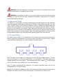
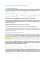
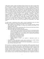
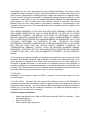
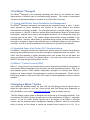
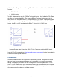
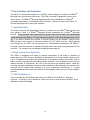
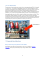
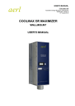
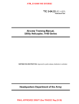
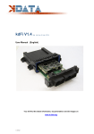
Pika S2001 PV Link™ Operation Manual Pika-‐energy.com Operation Manual for the S2001 PV Link™ REbus™ Converter Revision Table Revision Date Changes 1.0 2014-05-15 Initial Release 1.0.1 2014-08-26 Formatted many unneeded spaces, corrected error regarding enabling/disabling PVL via REview dashboard. 1 General Remarks Congratulations! You have purchased the Pika Energy S2001 PV Link™, a REbus™ compatible photovoltaic converter module. The S2001 is the result of the Pika team’s careful development and testing, building on decades of experience in the fields of power electronics and renewable energy systems. The S2001 is an electrically non-isolated single-stage converter designed for high-efficiency conversion between a photovoltaic panel and REbus™ Microgrid. This converter is passively cooled for high reliability and low noise. An interleaved converter topology ensures added reliability. The S2001 PV Link uses advanced algorithms to ensure maximum power extraction from the photovoltaic cells. What is REbusTM? The underlying technology behind Pika Energy’s S2001 Converter is an innovative energy management technology or ‘smart microgrid’ called REbus™. REbus™ is a DC energy network that operates alongside the existing AC infrastructure, enabling customers to build costeffective, scalable renewable energy systems. The REbusTM network is designed to serve as an open interconnection standard for networking next-generation energy technology – like Wi-Fi or USB for green energy! IMPORTANT! Only REbusTM compatible components may be used in connection with this converter. Do not connect the output of this module to any non-REbusTM modules. Ensure proper installation procedures when installing the S2001 PV Link module, any incorrect connections can result in serious property damage and/or personal injury may result. 2 Contents Operation Manual for the S2001 PV Link™ REbus™ Converter ................................................ 1 Revision Table .............................................................................................................................. 1 General Remarks ......................................................................................................................... 2 1 Regarding this Document ........................................................................................................ 4 2 Important safety information and instructions ............................................................................ 4 2.1 Appropriate Usage .............................................................................................................. 5 2.2 DC Input Details .................................................................................................................. 5 3 Notes concerning installation and operation .............................................................................. 6 3.1 Intended (normal) use ......................................................................................................... 6 3.2 Pika Energy Factory Limited Warranty ............................................................................... 6 3.3 Service ................................................................................................................................ 8 4 The REbusTM Microgrid ............................................................................................................. 9 4.1 Simple and Efficient Power Distribution and Management ................................................. 9 4.2 Integrated Power Line Carrier (PLC) Communications ....................................................... 9 4.3 REbus™ Control Protocol (RCP) ........................................................................................ 9 5 Designing a REbus™ System ................................................................................................... 9 6 Installation ............................................................................................................................... 10 7 User Interface and Operation .................................................................................................. 11 7.1 Enable/Disable .................................................................................................................. 11 7.2 High Temperature Operation ............................................................................................ 11 7.3 LED Notifications .............................................................................................................. 11 9 Maintenance ............................................................................................................................ 12 10 Troubleshooting ..................................................................................................................... 12 10.1 Fuse Replacement .......................................................................................................... 13 11 Frequently Asked Questions ................................................................................................. 13 12 Specifications ........................................................................................................................ 14 13 Mechanical Drawings ............................................................................................................ 15 3 1 Regarding this Document This manual contains important instructions for the S2001 Converter that must be followed during installation and maintenance of the converter. The S2001 is designed and tested according to international safety requirements, but as with all electrical and electronic equipment, certain precautions must be observed when installing and/or operating the S2001. To reduce the risk of personal injury and to ensure the safe installation and operation of the S2001, you must carefully read and follow all instructions, cautions and warnings in this user manual. Store this manual so that it is always easily accessible. 1.1 Symbols used in this document WARNING: This indicates a fact or feature very important for the safety of the user to prevent injury or death and/or which can cause serious hardware damage if not applied appropriately. 1.3 Data Label A permanently affixed label indicating the device specifications, serial number, and manufacturing date is located on the bottom surface of the converter enclosure. Tampering with label can void warranty. 2 Important safety information and instructions IMPORTANT SAFETY INSTRUCTIONS SAVE THESE INSTRUCTIONS This manual contains important instructions for model S2001 that shall be followed during installation and maintenance of the Pika S2001 Converter. WARNING: Before installing the Pika Energy S2001 Converter, read all instructions and caution markings in this manual and on the S2001 as well as on other REbus™ devices. WARNING: Electrical installation in the United States shall be done in accordance with all local electrical codes and/or the National Electrical Code (NEC), ANSI/NFPA 70. 4 WARNING: Electrical installation in Canada shall be done in accordance with all local electrical codes and/or the Canadian Electrical Code. WARNING: Connecting the S2001 to the electric utility grid must only be done after receiving prior approval from the utility company and installation completed only by qualified personnel/licensed electrician(s). 2.1 Appropriate Usage The S2001 is an electrically non-isolated single-stage converter designed for high-efficiency conversion between a photovoltaic panel array and a REbus™ Microgrid tied inverter (e.g. The X3001 Inverter). Refer to the converter installation guide for detailed information about the product and its intended use. The converter may only be operated with other REbus™ devices. Do not use the converter for purposes other than those described here. Alternative uses, modifications to the converter or the installation of components not expressly recommended or sold by the manufacturer void the warranty claims and operating permission. Contact the Pika Energy technical support if you need clarification regarding proper use of the converter. 2.2 DC Input Details The S2001 input is ONLY to be connected to a DC output from a photovoltaic panel array. When PV panels are tied together to be put into an array, they need to be put in series. A figure is provided below depicting how to connect multiple PV panels together. Note: The open circuit voltage is the voltage of all of the PV panels added together. The PV open circuit voltage (VOC) can never exceed 360VDC for safe operation. The highest open circuit voltages typically occur on cold days. The maximum power point voltage (VMP) cannot exceed 320 VDC (this value can be found on your PV panel datasheet). Note: PV panels manufactured by Sunpower™ are positive grounded panels and are not recommended for use with the S2001. Warning: The converter is designed to work strictly with photovoltaic panels and could result in damage to the S2001 converter and/or personal injury if connected to any other source. 5 3 Notes concerning installation and operation 3.1 Intended (normal) use Your converter is strictly constructed according to approved safety requirements. Improper use may lead to lethal hazards for operators and/or damage to devices and property. The S2001 includes important safety features such as overvoltage and overcurrent fault protection. REBUS™ OUTPUT CONNECTION ONLY! The S2001 is designed to output regulated direct current (DC) for REbus-compatible converters which then is converted into grid-compatible alternating current (AC). DO NOT CONNECT PHOTOVOLTAIC MODULES DIRECTLY TO THE REBUS™ OUTPUTS OF THE S2001 converter, this is the OUTPUT of the S2001 converter. DOING SO WILL VOID THE WARRANTY AND MAY DAMAGE THE CONVERTER. Any use other than the specified intended use shall not be deemed intended or normal use, and may result in property damage, personal injury or death. Pika is not liable for damage or injuries caused by unintended use. Damage caused by unintended use is at the sole risk of the operator. “Intended use” shall also include adherence to the operating and installation instructions. Your trained and authorized installer must obtain all necessary permits and agreements from your local government and your utility company for a legal and code-compliant installation of your REbusTM Microgrid system. 3.2 Pika Energy Factory Limited Warranty Pika Energy LLC (“Pika”) has developed a reliable, efficient photovoltaic converter, designated S2001 (“Converter”), that is designed to withstand normal operating conditions when used in accordance with its intended use and in compliance with instructions in the accompanying Installation Manual and User Manual shipped with the unit. The Pika limited warranty (“Limited Warranty”) covers defects in workmanship and materials of the Pika Converter (“Defective Product”) for a period of ten (10) years from the date of original purchase of such Converter at point of sale to the originally-installed end user location (the “Warranty Period”). During the Warranty Period, the warranty is transferable to a different owner as long as the Converter remains installed at the originally-installed end user location. During the Warranty Period, if Pika determines through inspection the existence of a defect that is covered by the Limited Warranty, Pika will at its option, either (1) repair or replace the Defective Product free of charge, or (2) provide a credit or refund to the owner of the system at the originally installed end user location in an amount not to exceed the then-current price of (a) a “like kind” converter that is available for purchase by the system owner at the time of the Limited Warranty claim, or (b) the original cost of the Pika Converter that is subject to a Limited Warranty claim. 6 If Pika elects to repair or replace the Defective Product, Pika will, at its option, use new and/or reconditioned parts in repairing or replacing the Defective Product. Pika reserves the right to use parts or products of original or improved design in the repair or replacement of Defective Product. If Pika repairs or replaces a Defective Product, the Limited Warranty continues on the repaired or replacement product for the remainder of the original Warranty Period or ninety (90) days from the date of Pika’s return shipment of the repaired or replacement product, whichever is later. The Limited Warranty covers both parts and labor necessary to repair the Defective Product (if Pika elects to repair the Defective Product), but does not include labor costs related to (i) un-installing the Defective Product or (ii) if applicable, re-installing a repaired or replacement product. To the extent applicable, the Limited Warranty also covers the costs of shipping a repaired or replacement product from Pika, via a non-expedited freight carrier selected by Pika, to locations within the United States (including Alaska and Hawaii) and Canada, but not to other locations outside the United States or Canada. The Limited Warranty does not cover, and Pika will not be responsible for, shipping damage or damage caused by mishandling by the freight carrier and any such damage is the responsibility of the freight carrier. To obtain repair or replacement service, credit or refund (as applicable) under this Limited Warranty, the customer must comply with the following policy and procedure: • Many problems can be addressed in the field. Prior to returning a product, customer must contact Pika technical support to evaluate and troubleshoot the problem in the original installation setting. • All Defective Product must be returned with a Return Merchandise Authorization Number (RMA) which customer must request from Pika. • Requests for RMA must include the following information: o Proof-of-purchase of the Defective Product in the form of (1) the dated purchase receipt from the original purchase of the product at point of sale to the end user, or (2) the dated dealer invoice or purchase receipt showing original equipment manufacturer (OEM) status, or (3) the dated invoice or purchase receipt showing the product exchanged under warranty o Model number of the Defective Product o Serial number of the Defective Product o Detailed description of the defect. o Shipping address for return of the repaired or replacement product (as applicable). • All Defective Product authorized for return must be returned in the original shipping container or other packaging that is equally protective of the product. • The returned Defective Product must not have been disassembled or modified without the prior written authorization of Pika. Pika Converters are designed to withstand normal operating conditions and typical wear and tear when used for their original intent and in compliance with the installation and operating instructions supplied with the original equipment. The Limited Warranty does not apply to, and Pika will not be responsible for, any defect in or damage to any Pika converter: (1) that has been misused, neglected, tampered with, altered, or otherwise damaged, either internally or externally; (2) that has been improperly installed, operated, handled or used, including use under conditions for which the product was not designed, use in an unsuitable environment, or use in a manner contrary to the Pika User Manual or applicable laws or regulations; (3) that has 7 been subjected to fire, water, generalized corrosion, biological infestations, acts of God, or input voltage that creates operating conditions beyond the maximum or minimum limits listed in the Pika Converter specifications, including high input voltage from generators or lightning strikes; (4) that has been subjected to incidental or consequential damage caused by defects of other components of the system; or (5) if the original identification markings (including trademark or serial number) of such Converter have been defaced, altered, or removed. The Limited Warranty does not cover costs related to the removal, installation or troubleshooting of the customer’s electrical systems. The Limited Warranty does not extend beyond the original cost of the Pika Converter. THE LIMITED WARRANTY IS THE SOLE AND EXCLUSIVE WARRANTY GIVEN BY PIKA AND, WHERE PERMITTED BY LAW, IS MADE EXPRESSLY IN LIEU OF ALL OTHER WARRANTIES, EXPRESS OR IMPLIED, STATUTORY OR OTHERWISE, INCLUDING, WITHOUT LIMITATION, WARRANTIES OF TITLE, QUALITY, MERCHANTABILITY, FITNESS FOR A PARTICULAR PURPOSE OR NONINFRINGEMENT OR WARRANTIES AS TO THE ACCURACY, SUFFICIENCY OR SUITABILITY OF ANY TECHNICAL OR OTHER INFORMATION PROVIDED IN MANUALS OR OTHER DOCUMENTATION. IN NO EVENT WILL PIKA BE LIABLE FOR ANY SPECIAL, DIRECT, INDIRECT, INCIDENTAL OR CONSEQUENTIAL DAMAGES, LOSSES, COSTS OR EXPENSES HOWEVER ARISING, WHETHER IN CONTRACT OR TORT, INCLUDING WITHOUT LIMITATION ANY ECONOMIC LOSSES OF ANY KIND, ANY LOSS OR DAMAGE TO PROPERTY, OR ANY PERSONAL INJURY. To the extent any implied warranties are required under applicable law to apply to the Pika Converter, such implied warranties shall be limited in duration to the Warranty Period, to the extent permitted by applicable law. Some states and provinces do not allow limitations or exclusions on implied warranties or on the duration of an implied warranty or on the limitation or exclusion of incidental or consequential damages, so the above limitation(s) or exclusion(s) may not apply. This Limited Warranty gives the customer specific legal rights, and the customer may have other rights that may vary from state to state or province to province. 3.3 Service WARNING: Do not attempt to repair the S2001 Converter. The converter contains no userserviceable parts. If the Pika S2001 Converter fails, first contact Pika customer service at 207-632-8040 for troubleshooting help. See the Warranty section for details on terms and conditions for repair or replacement under warranty. You must obtain an RMA (Returned Merchandise Authorization) number prior to returning the unit. Obtain the assistance of a skilled and qualified installer to safely disconnect the converter for shipment. Technical Support Information: • • • Support department hours: 9AM to 5PM Eastern Standard Time Zone, Monday – Friday (excluding holidays) Phone: 207-887-9105 Email: [email protected] 8 4 The REbusTM Microgrid The REbusTM Microgrid is the underlying technology that allows for the efficient and robust interconnection of different types of renewable energy products. This section is informational only and not required knowledge for operation of your Pika S2001 Converter. 4.1 Simple and Efficient Power Distribution and Management The REbusTM Microgrid architecture was designed with renewable energy in mind. A cleansheet approach to power distribution has resulted in the most practical and efficient interconnection technology available. The microgrid operates at variable voltage in a defined band, between +/- 180-200 V relative to ground which simultaneously allows for efficient power transmission, reduced shock hazard, and simplified electronics for a bidirectional utility grid converter such as the S2001. The variable voltage communicates energy availability to the attached REbus™ devices, which allows for prioritized energy storage and load shedding. The microgrid is designed to support many different types of renewable energy sources and power converters, as well as accommodating future DC loads that are presently in development. 4.2 Integrated Power Line Carrier (PLC) Communications The REbus™ microgrid standard also specifies an optional power line carrier communication technology that enables devices on the same microgrid to communicate with one another. The X3001 uses this capability to gather information about your system such as the status and energy production of your Pika T701 Wind Turbine or your solar array, which connects to the REbus™ microgrid through the Pika S2001 PV Link. 4.3 REbus™ Control Protocol (RCP) REbus™ Control Protocol is a communications protocol developed specifically for the transfer of data between REbus-compatible power converters and data management products. RCP is an open-standard protocol which enables independent developers to interface with REbus™ products and create software and applications to enhance user experience. Please visit the Pika Energy website to learn more about RCP and the software applications that are currently available. 5 Designing a REbus™ System Your trained and qualified installer will work with the Pika Energy technical support team to design the right system for your site. Please consult with Pika Energy sales department at (207)-632-8040 or on the web at www.pika-energy.com to find an installer near you. The Pika Energy product system is designed from the ground up for unmatched flexibility. First and foremost, the X3001 inverter accepts input from any combination of REbus™ compatible sources. In fact, the X3001 inverter supports up to 32 devices on the REbus™ microgrid network, and the automatic power management capability of REbus™ allows the total power rating of sources on the network to exceed the converter power rating by up to 2X. As of 9 publication, Pika Energy offers the following REbus™ products in addition to the S2001 PV Link Converter: • • T701 Wind Turbine X3001 Inverter The S2001 is intended for use with a REbus™ microgrid inverter. As of publication Pika Energy only offers one inverter, the X3001. The beauty of REbus™ microgrid technology is that it allows the user to add multiple REbus™ microgrid devices to one inverter. A proposed system setup is shown on the following page which uses two S2001 PV Link devices and one X3001 Inverter. The RE+ and RE- lines denote the REbus™ microgrid +/-190VDC lines. Proposed System Setup Using Two S2001 PV Link Converters and One X3001 Inverter Check the Pika Energy website at http://www.pika-energy.com/products for the latest selection of REbus-compatible product offerings! 6 Installation Converter installation should only be performed by trained personnel. Along with this manual there is an insert of a mounting hole drawing that is to scale of the converter mounting hole spacing. This page is provided for the use of drilling holes and mounting the S2001 PV Link device. Be sure to remove the paper template after drilling the holes and before the converted is mounted. The converter should be mounted with at least 12 inches of space between the top of the converter and the ceiling for ventilation purposes. 10 7 User Interface and Operation The S2001 is a devices that regulates a +/-190VDC output voltage for connection to REbusTM Microgrid from a photovoltaic panel array. The S2001 converter is designed to convert up to 2kW of power. The REbusTM Microgrid technology allows for parallelization of REbusTM compatible input devices, including the S2001 converter. Below is a figure of the S2001 PV Link housing along with its basic user elements. 7.1 Enable/Disable The S2001 Converter will automatically detect the presence of the REbusTM Microgrid and will only operate if there is a REbusTM Microgrid already established by a REbusTM Microgrid Inverter. If the converter was enabled prior to power down, the converter will automatically enable and begin functioning. If it was previously disabled, it will remain disabled after powerup. If you want to disable the converter to conserve power you can disable it using the user interface menu on the screen of an inverter module (e.g. The X3001 Inverter). When disabled but powered up, the S2001 will still operate as a communications gatewayfor the REbus™ microgrid. Once the converter is disabled, the photovoltaic array input is disconnected from the converter. The converter can be enabled through the same menu(s). 7.2 High Temperature Operation The S2001 is designed and tested to operate continuously at full power in ambient air temperature up to 50C. However, installation in tight spaces (e.g. closets), direct exposure to full sun, or installations that hamper the effectiveness of the passive cooling system may result in higher converter temperatures and reduced power operation. If the maximum power has been reduced because of temperature, the LED on the converter will illuminate yellow. While the converter has been designed to operate in these conditions without damage, the lifetime of the converter will be longer when operated in a lower temperature environment. It is highly recommended that the converter be installed in well-ventilated areas, and out of direct sunlight if possible. 7.3 LED Notifications There is a multicolor LED indicates the status of the S2001 PV Link REbus™ microgrid converter. A “strobing” LED is defined as a blink once every 5 seconds and a “blinking” LED is defined as continuous blinking. 11 This LED provides an indication for the status of the S2001 converter LED Color Description X3001 Status Code Blinking Blue Standby mode Standby State Blinking Green The converter is connecting the state of the REbusTM Initialization State Strobing Green The converter is in a low sun state Low Input Power State Solid Green The converter has connected to your REbusTM Microgrid system Making Power State Blinking Yellow The REbusTM Microgrid voltage is low Low REbusTM Voltage State Solid Yellow The converter is being run in a limited power state Limiting Power State Blinking Red Generic error message (contact technical support) Generic Error State Strobing Red The converter is disabled Disabled State Off There is no power to the converter (no REbusTM voltage) Off State The S2001 unit does not have a user interface itself, but there is both a user interface on the inverter module (e.g. The X3001 Inverter) as well as the REviewTM online user interface. Refer to the X3001 manual for information on both the X3001 inverter user interface as well as information on the online user interface, REviewTM. 9 Maintenance In general the Pika S2001 does not require any regular maintenance. 10 Troubleshooting In the event the converter is not behaving as expected or is in a fault state, please contact your installer and/or Pika Technical Support. 12 10.1 Fuse Replacement There are no user serviceable parts except for the two fuses protecting the REbus™ microgrid +/-190VDC lines. If you suspect a fuse of failure contact Pika Technical Support for further information on acquiring new fuses. DO NOT replace either of these fuses with a fuse that isn’t approved first by Pika Energy, this could result in unsafe operating conditions as well as damage to the device and/or personal injury. Your installer can obtain a replacement fuse and install it for you if you do not feel comfortable replacing it yourself. On the following page is a figure depicting the inside of the S2001 module and where the fuse holders are located. They are long black cylinders with gray screw caps. In order to replace the fuses simply take a screwdriver and twist the fuse holder until the cap unscrews and can be removed. Replace the fuse and then reinsert the fuse holder in the cylinder and screw the gray holder with the screw cap back into place (the fuse isn’t polarized so it can be put in either way). Fuse Holders 11 Frequently Asked Questions Why is there only one question in the FAQ? Pika engineers are waiting for more questions to come in! So navigate to www.pikaenergy.com, submit your question and perhaps it will get added to the list. 13 12 Specifications The S2001 converter produces a regulated DC current output of +/-190VDC, and is designed exclusively for connection to a REbusTM DC microgrid. Displayed below are two tables of general and electrical specifications of the converter. Technical Specifications Min Nom Max Units - - 2000 W 100 - 320 VDC PV Open Circuit Voltage (VOC) - - 360 VDC Input PV Array Current 0 - 10 A PV Link Electrical Output - +/-190 - VDC REbus Power - - 2000 W REbus Voltage - 380 420 VDC REbus Output Current 0 - 8 A Operating Temperature -20 50 60 C Rated Power (approx.) Maximum Power Point Voltage (VMP) General Specifications Details Enclosure Type NEMA 3R - Enclosure Material Powder-Coated Steel - Thermal Management Passive convection cooling - Weight 4.5 (10) Size 235(9.25) W x 210(8.25) H x 102(4) D Wire Size 10-14 AWG Warranty 10 years standard Years 14 Units kg (lb) mm (in.) 13 Mechanical Drawings 15 16