1
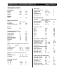
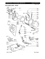
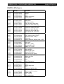
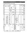
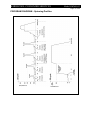
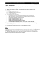
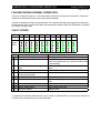
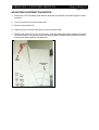
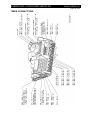
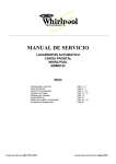
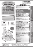
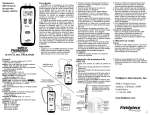
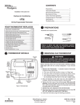
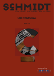
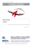
WHIRLPOOL CONSUMER SERVICES
Model AWM8143
October 2001
WHIRLPOOL AUSTRALASIA
CONSUMER SERVICES
SERVICE MANUAL
FRONT LOAD
WASHING MACHINE
Model AWM8143
Version 8570 814 53100
Copyright © 2001 Whirlpool (Australia) Pty. Limited
All rights strictly reserved. Reproduction or issue to third parties in any form whatsoever is
not permitted without written authority of Whirlpool (Australia) Pty. Limited
Whirlpool is a registered trademark of Whirlpool U.S.A.
This documentation is intended only for qualified technicians who possess the required qualifications and
are aware of the regulatory requirements applicable to servicing electrical appliances.
Whirlpool (Australia) Pty Limited
A. B. N. 28 003 578 023
Part No. SM3023
WHIRLPOOL CONSUMER SERVICES
Model AWM8143
Page 2 of 20
BLANK PAGE
WHIRLPOOL CONSUMER SERVICES
Model AWM8143
Page 3 of 20
CONTENTS
Page
TECHNICAL DATA
4-5
EXPLODED VIEW - CABINET
6
EXPLODED VIEW - DRUM
7
SPARE PARTS LIST
8 - 10
WIRING DIAGRAM
11
CIRCUIT DIAGRAM
12
PROGRAM DIAGRAM - Cotton
13
PROGRAM DIAGRAM - Synthetic
14
PROGRAM DIAGRAM - Delicate
15
PROGRAM DIAGRAM - Wool and Silk
16
PROGRAM DIAGRAM - Spinning Profiles
17
FAULT DIAGNOSIS
18
TEST SEQUENCE
19
FAILURE DURING NORMAL OPERATION
20
ADJUSTING DISTRIBUTION NOZZLE
21
TIMER CONNECTIONS
22
WHIRLPOOL CONSUMER SERVICES
Model AWM8143
Page 4 of 22
TECHNICAL DATA
Dimensions
Height
Width
Depth
845
595
620
mm
mm
mm
Weight
Nett
79
kg
Mains Connection
Voltage
Frequency
Power consumption
230 - 240 V
50
Hz
2.2
kW
Drum
Volume
48
Capacity of dry laundry
Cotton/coloured
6
Cotton rapid
3
Cotton short
6
Easy care
2.5
Easy care rapid
1.5
Easy care short
2.5
Delicate
1.5
Wool
1
l
kg
kg
kg
kg
kg
kg
kg
kg
Water Level (as sensed by the pressure
switch)
Level 1
Switching point
45± 5
mmWc
Reset point
30± 5
mmWc
Overflow
300 ± 20 mmWc
Water (level visible inside the drum)
Level 1
Switching point
25 - 39
mm
Overflow
287 - 326 mm
Nominal currents
Contacts
11 - 12
11 - 14
11 - 16
4 (4)
16 (4)
1 (1)
A
A
A
Door lock
Lock time (20 °C)
Unlock time
Voltage
Rated current:
Contact 4 - 5
3-6
60 - 90
230 - 240
s
s
V
16 (4)
A
Heating element
Heating
Tubular heating element with
NTC - sensor
Rated Voltage
230 - 240
V
Rated power
2050
W
Resistance
22 - 28
Ω
Resistance NTC :
0°C
30°C
40°C
50°C
60°C
70°C
95°C
35.9
9.8
6.6
4.6
3.2
2.3
1.1
Inlet valve - Cold/hot fill :
Water temp (max)
60
Rated flow <1 bar
8
Pressure range
50 - 1000
Nominal voltage
220 - 240
Frequency
50
Minimum starting voltage:
< 600 kPa
160
600 - 1000 kPa
170
Nominal current
35
Nominal input
6
Nominal (20 °C)
3.4 - 4.5
Drain pump (synchronous)
Nominal Voltage
230 - 240
Nominal current
0,3
Nominal power
34
Frequency
50
Resistor (coil)
155 ± 7%
Motor protection
170
Capacity(H=1,25m) 15 ± 2
kΩ
kΩ
kΩ
kΩ
kΩ
kΩ
kΩ
°C
l/min
kPa
V
Hz
V
V
mA
VA
κΩ
V
A
W
Hz
Ω
°C
l/min
WHIRLPOOL CONSUMER SERVICES
Model AWM8143
Page 5 of 22
TECHNICAL DATA (Cont.)
Program timer
Type SC1
Timer basic 4619 710 67641
Timer programmed 4619 710 69741
Nominal voltage 230 - .240
V
Frequency 50 Hz
Speeds
Wash speed
Ramp speed
Spin speed
Harness Connectors (See circuit
diagram)
OA4.1 - OA4.2
Option 5
OA4.3 - OA4.4
Option 6
OB4.1 - OB4.2
Option 3
OB4.3 - OB4.4
Option 4
OC4.1 - OC4.2
Option 1
OC4.3 - OC4.4
Option 2
SLT3.1 - SLT3.3 Temperature selector
SLS4.1 - SLS4.4 Spin speed selector
VCF3.1 - VCF3.3 Valve (cold water)
VHF3.1 - VHF3.3 Valve (hot water)
Pi5.1 =
negative supply
Pi5.2 =
data
Pi5.3 =
clock
Pi5.4 =
positive supply
Pi 5.5 =
negative supply
PL3.1 - PL3.3
Pilot lamp
Connector
M7.1 - M7.7
DP2.1 - DP2.2
SET2.1 - SET2.2
DSS3.1 - DSS3.3
PR2.1 - PR2.2
Motor
Pump
NTC
Door switch
Pressostat
Single connector
HE2.1 - HE2.2
Heating element
PS2.1 - PS2.2
Pressostat
SM3.2 - SM3.3
Mains switch (3 fold
connector)
Program 32 positions
Step
Pre
wash
Main
wash
Rinse
Spin
Stop
Cotton
/
Colour
02-06
Easy
care
Delicate
Wool
Silk
03-06
04-06
-
-
07-21
12-21
14-21
17-21
18-21
22-28
29-31
32
22-28
29-31
32
22-28
29-31
32
22-28
29-31
32
22-28
29-31
32
54 rpm
95 rpm
1400 rpm
Ambient Temperatures
Ambient temperature up to 70 °C
Storage temperature up to 85 °C
Output
Motor M7.6 - DSS 3.2
>40
in pump step AQ2.1 -DSS 3.2 240
NTC
not measurable
Pump DP2.1 -DP2.2
240
Doorlock DSS3.1 -DSS 3.3 240
Pressostat E4 - E2
240
- empty PR2.1 - E2
240
- full PR2.2 - E2
240
Valve (Rast 2,5) V2.1 - V2.2 >170
Options
not measurable
Display module Pi5.1 - Pi5.
5
Pi5.4 - Pi5.5
12
V
V
V
V
V
V
V
V
V
V
Motor
Type MCA61/64 - 148 t.f./BkD0
Belt ratio
i = 1 : 12.4
Resistance contacts
6-7
68.7± 7% Ω
4-5
1.78± 7% Ω
2-3
1.68± 7% Ω
1-3
0.99± 7% Ω
WHIRLPOOL CONSUMER SERVICES
Model AWM8143
Page 6 of 22
EXPLODED VIEW - CABINET
WHIRLPOOL CONSUMER SERVICES
Model AWM8143
Page 7 of 22
EXPLODED VIEW - DRUM
WHIRLPOOL CONSUMER SERVICES
Model AWM8143
Page 8 of 22
PARTS LIST
Item
001 0
002 0
003 0
004 0
011 0
021 0
024 0
025 0
030 0
040 0
050 0
061 1
065 0
065 1
065 2
065 4
065 5
081 0
081 1
084 0
084 1
086 0
086 2
110 0
130 0
130 1
131 0
131 1
131 2
135 1
135 2
135 3
140 0
143 0
144 0
191 0
191 1
191 2
200 0
201 0
210 0
210 1
220 0
271 0
272 0
Part No
4812 440 18996
4812 440 19343
4812 464 48112
4812 440 18993
4812 500 18068
4812 440 19783
4812 440 18998
4812 404 38551
4812 310 18586
4812 417 18787
4812 459 38021
4812 466 88464
4812 310 18339
4812 310 18236
4812 310 18399
4812 310 18335
4812 310 18336
4812 466 48057
4812 502 18424
4812 466 58001
4812 404 68021
4812 401 18409
4812 401 18412
4812 498 18139
4812 417 28047
4812 417 28048
4812 417 28046
4812 417 28045
4812 492 58022
4812 498 18137
4812 492 58023
4812 290 68153
4812 450 68218
4812 440 19782
4812 440 19589
4812 466 68557
4812 492 18015
4812 492 98011
4812 418 18181
4812 464 48002
4812 520 18034
4812 452 18994
4812 418 18246
4812 358 18157
4812 528 58004
Description
Cabinet
Flap
Traverse BK-cold
Drip tray assy
Foot variable
Front VBL WH
Panel, rear
Support control board VBL WH
Table top VBL WH
Hinge
Plinth OMEGA
Counter weight, SS-TUB, 1400
Insulation Front Pane
Insulation
Insulation
Insulation Middle Pane
Insulation Lower
Shock absorber
Screw damper
Anti rattle, support spring
Holder
Holder Shock Absorber
Stopper
Handle, door white
Plate Door lock
Plate Doorlock Lower
Lock Door
Pin Door Lock
Spring Door Lock
Knob Door safety
Spring Door Safety
Holder, adjustable, Door Safety
Door glass
Glassdoor frame VBL WH
Frame, door glass DE-WT
Door bellow
Strap Fix. Bellow
Strap
Tub
Bottom tub
Crosspiece
Screw M8x20 A2F
Drum 1600
Belt BK 1254 J5
Pulley
WHIRLPOOL CONSUMER SERVICES
Model AWM8143
Page 9 of 22
PARTS LIST (Cont.)
Item
272 1
272 2
272 3
292 0
301 0
303 0
321 0
321 1
331 0
332 1
332 2
332 3
332 4
332 5
400 0
400 1
409 0
421 0
430 0
451 0
490 0
491 0
500 0
581 0
620 0
630 0
631 0
631 1
691 0
701 0
701 0
701 1
702 0
703 0
707 0
707 1
707 2
707 3
708 1
711 0
712 0
713 0
717 0
717 1
717 2
Part No
4812 532 28006
4812 532 18024
4819 502 18417
4812 530 58003
4812 452 10632
4812 498 18189
4812 452 10631
4812 532 98011
4812 412 78631
4812 513 18097
4812 513 18098
4812 513 18099
4812 513 18101
4812 513 18102
4812 361 58091
4812 502 18361
4812 362 48004
4812 121 18142
4812 310 38524
4812 259 28772
4812 310 18404
4812 321 28367
4812 282 18804
4812 271 28434
4812 239 58002
4812 280 58019
4812 271 38358
4812 360 58112
4812 282 18702
4812 530 28781
4819 530 28926
4819 466 69704
4819 530 29019
4812 530 48162
4812 526 48031
4812 526 48028
4812 530 48161
4812 530 78011
4812 530 48141
4812 418 68166
4812 418 88051
4812 418 88019
4812 418 78925
4812 321 38013
4812 321 38012
Description
Bushing conical
Washer
Screw
Gasket tub bottom
Control panel
Handle, drawer VBL WH print.
Insert panel
Fastener for inlay
Knob, VBL WH electr.print
Push button Start VBL WH
Push button spin speed VBL WH
Push button option VBL WH
Push button plus VBL WH
Push button minus VBL WH
Motor MCA61/64-148-1400
Screw M8x30
Brush, carbon motor CESET
Interference filter 1,00 µF
Drain pump
Heating element, 2050W 240V + NTC
Kit cable, mains 5m 3x1,5
Strain relief
Timer SC1, 1400
Pressostat SC1-SS
Module ""A"" C/DS
Door lock
Switch MICRO
Floater Kit BK, WH
Sensor NTC (SC1)
Hose, inlet 3,8 m (Eltek)
Hose, inlet 2,5 m (Eltek)
Gasket and filter
Hose intern
Hose
Nozzle Distribution
Nozzle
Fitting
Washer edge disc
Bend
Dispenser OMEGA-3CH
Drawer Detergent
Flap Detergent Container
Bowden cable
Lever , Nozzle
Holder,adjustable
WHIRLPOOL CONSUMER SERVICES
Model AWM8143
Page 10 of 22
PARTS LIST (Cont.)
Item
717 3
717 4
717 5
718 0
718 1
750 0
753 1
754 0
754 1
760 0
781 0
782 0
783 1
783 3
783 4
785 0
785 1
786 3
787 0
787 2
794 2
794 5
900 0
900 1
900 2
900 3
900 4
900 9
910 5
921 0
930 0
941 0
941 1
953 0
961 0
962 0
962 1
965 0
965 1
993 0
993 3
Part No
4812 278 88007
4812 492 38359
4812 282 18807
4812 526 48027
4812 418 88018
4812 530 48139
4812 418 68125
4812 530 28838
4812 401 18054
4812 480 58085
4819 530 28959
4812 530 28816
4812 530 28822
4812 530 18001
4812 530 28818
4812 530 28812
4812 462 79663
4812 530 28809
4812 530 28819
4812 401 18157
4812 530 58005
4812 530 58015
4812 255 18204
4812 290 88043
4812 290 88046
4812 290 88048
4812 401 18414
4812 401 48569
4812 903 08196
4812 011 18522
4812 492 38361
4812 520 28003
4812 520 28005
4812 530 68001
4812 395 98005
4812 466 38011
4812 238 58001
4812 466 68545
4812 440 18992
4819 530 29028
4812 395 58004
Description
Slide
Spring , Nozzle
Cam 3 C. SC1/VBL/WH
Siphon 3 - Chamber
Accessory
Boiler
Chamber, air
Drainhose
Clamp, hose
Filter set pump
Hose
Hose Pressostat
Hose
Connection Part
Hose
Hose Draining
Threaded cap OMEGA
Hose Aqua-Stop
Hose with hole
Strap 32-50/9 C61
O-Ring
Gasket
Holder Hose outlet
Bracket Door lock
Cable clamp
Cable clamp
Clamp, hose
Clamp hose pressostat
Screw M 5X14-Z
Ring, circlip 52x2
Spring Suspension 1200
Bearing, ball 6306
Bearing, ball 6304
Shaft seal V 40 A
Lever, security
Cover, protect. heating element
Protector, elecrical parts
Cover BK/WH
Lid Rearcover
Bow
Tool
00
11
22
33
44
55
66
77
88
99
45
Black
Brown
Red
Orange
yellow
Green
Blue
Violet
Grey
White
Yellow/Green
WHIRLPOOL CONSUMER SERVICES
WIRING DIAGRAM
Model AWM8143
Page 11 of 22
AQS
CUIO
DP
DSS
HE
iF
m
PR
SET
SM
TI
TIM
V
VHS
Aquastop switch
Control unit, user IO
Drain Pump
Door safety switch
Element
Interference filter
Motor drive
Pressure switch
Sensor, temperature
Switch, mains
Timer
Timer motor
Cold water valve
Hot water valve
WHIRLPOOL CONSUMER SERVICES
CIRCUIT DIAGRAM
Model AWM8143
Page 12 of 22
WHIRLPOOL CONSUMER SERVICES
Model AWM8143
Page 13 of 22
PROGRAM DIAGRAM - Cotton
WHIRLPOOL CONSUMER SERVICES
Model AWM8143
Page 14 of 22
PROGRAM DIAGRAM - Synthetic
WHIRLPOOL CONSUMER SERVICES
Model AWM8143
Page 15 of 22
PROGRAM DIAGRAM - Delicate
WHIRLPOOL CONSUMER SERVICES
Model AWM8143
Page 16 of 22
PROGRAM DIAGRAM - Wool and Silk
WHIRLPOOL CONSUMER SERVICES
Model AWM8143
Page 17 of 22
PROGRAM DIAGRAM - Spinning Profiles
WHIRLPOOL CONSUMER SERVICES
Model AWM8143
Page 18 of 22
FAULT DIAGNOSIS
1.
The diagnostic tests must be performed on the machine without a wash load because the
out of balance detection system is disabled.
2.
Set the cycle selector to "DRAIN" and wait for the time display to indicate "0:02".
3.
Press the :
a) "RINSE HOLD" button twice
b) "INTENSIVE RINSE" button twice
c) "START" button once,
4.
The control panel will now display :
•
Temperature 60°C (Does not change for duration of the test sequence).
•
1400 speed LED on (Does not change for duration of the test sequence).
•
"PREWASH" programme sequence LED on
•
"WASH" programme sequence LED on
•
"RINSE" programme sequence LED on
•
"RINSE HOLD" programme sequence LED on
•
"SPIN" programme sequence LED on - (This is Step 1 in the Table over)
5.
Drain pump runs for approximately six seconds and the test sequence automatically
advances to Step 2.
6.
By pressing the Prewash button once, the timer advances to step 3.
Notes:
Each step of the test can be advanced by pressing the button in the next line of the "Advance to
step by pressing :" column in the table over once without waiting for the step to complete.
e.g. When the machine starts to fill in Step 2, the "Prewash" button can be pressed once to
advance to Step 3 without the 60 second fill to complete.
WHIRLPOOL CONSUMER SERVICES
Model AWM8143
Page 19 of 22
TEST SEQUENCE
Step Advance to step by Pump Out Temperor Fill Via : ature
pressing :
(See Note 1 below)
Time
1
Start
Pump out -
-
2
Advances
automatically
Prewash
3
Prewash button
4
Easy ironing
button
Main
wash
Main
wash
5
Advances
Main
automatically after wash
heating or turn
temp. to 20°C
(See Note 2)
Eco button
Cold fill.
Fill via
No heat.
fabric
softener
Rinse hold button Pump out -
6
7
8
9
Drum
Rhythm
Component(s)
Checked
PROGRAMME SEQUENCE
LED *
P
W
R
RH
D
Stationary Rinse hold and
Intensive rinse
buttons
Cold fill.
60 s (fill)
Stationary Prewash fill,
No heat
Aquastop lamp
(See Note 3 below)
Warm fill. 60 s (fill)
Stationary Prewash button
No heat.
and main wash fill
Warm fill. 60 s (fill) plus 10 s on, Heating circuit,
heating time 6 s off
NTC, leakage
(This fill
cannot be
bypassed)
Heat to
60°C
Cold fill.
55 s (fill)
80 s on, No heat.
2 s off
Advances
Pump out automatically
Rinse hold button Stop
-
60 s
80s on,
2s off
-
10s on,
Pump
6s off
Spin Max Pump, spin
speed
-
5.5 min
-
Fabric softener fill
*Programme Sequence LED's: P = Prewash W = Wash R = Rinse RH = Rinse Hold D = Drain
Note 1 Unless indicated by "Advances automatically", the test cycle can only be advanced by
pressing the appropriate button once within five minutes, otherwise the machine will
pump out and a false fault will be indicated.
Note 2. This part of the test sequence can be terminated after the fill by reducing the
temperature setting to 20°C but the NTC will not be checked for accuracy.
Note 3. The Aquastop lamp will illuminate during Step 3 only.
If a failure is detected during the test sequence the timer will :
1.
initiate the safety step routine :
A. Drain pump runs until pressure switch resets plus 30 seconds.
2.
I.
Main motor is turned off.
II.
Water inlet valves are turned off.
III.
Element is turned off
Stop the machine.
WHIRLPOOL CONSUMER SERVICES
Model AWM8143
Page 20 of 22
FAILURE DURING NORMAL OPERATION
If the red "Aquastop" light is on, the float switch under the unit has been actuated. Check the
machine for leaks and dry the area under the float switch.
If a fault is detected during normal operation, the machine will stop, the programme sequence
LED where the fault occurred will flash and the speed indicator LED's will illuminate in a pattern
to indicate the fault code.
FAULT CODES
Fault
1
FH
2
FA
3
FP
5
F05
6
F06
7
F07
8
F08
9
F09
11
F11
12
F12
14
F14
Speed
LED's
Fault
Detected Malfunction
Perform the following:
1 FH Water not entering or not detected Check tap, cold inlet valve, pressure switch
2 FA Aquastop failure
Check float switch under machine, empty any
water from catchment tray, check for water leaks
or oversudsing
3 FP Drain failure or not detecting empty Check pressure switch, blocked drain, drain
drum
pump
5 F05 NTC failure
Check NTC
6 F06 Tachometer failure (no motor
Check motor
movement detected)
7 F07 Circuit board failure (motor triac)
Check motor, replace timer
9 F09 Overflow failure
Check drain pump, pressure switch, blocked
drain
11 F11 Electronic failure
Replace timer
12 F12 Heater safety failure
Check heater and timer
14 F14 Electronic failure
Replace timer
To operate the machine after the test cycle or after an indicated fault, turn the cycle selector to
off then select the desired cycle and press Start.
WHIRLPOOL CONSUMER SERVICES
Model AWM8143
Page 21 of 22
ADJUSTING DISTRIBUTION NOZZLE
1. Select any COTTON wash cycle with the prewash off and wait until water begins to enter
machine.
2. Turn the machine off at the power point.
3. Remove the machine lid.
4. Adjust the lever until the red pointer is over the index mark.
5. Replace the machine lid, turn on the power, open the detergent drawer slightly and make
sure that water is only entering the main wash (middle) compartment and that no water is
entering the fabric softener compartment.
Index
Mark
Adjustment
Lever
WHIRLPOOL CONSUMER SERVICES
Model AWM8143
Page 22 of 22
TIMER CONNECTIONS