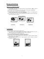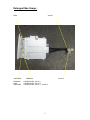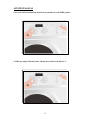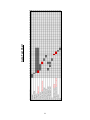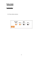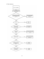
1
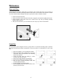
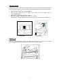
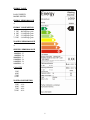
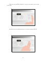
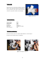
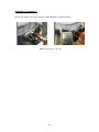
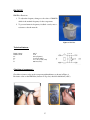
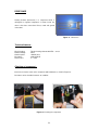
SERVICE MANUAL
INSTRUCTIONS FOR CUSTOMERS DURING INSTALLATION
The end users should be informed about the below subjects
1. General information (general specifications; energy class, etc.)
2. Seperating the laundry according to colour, type and properties.
3. Selecting the proper washing program and detergent/softener.
4. Usage of temperature and spinning adjustment knobs.
5. Maximum dry laundry weight according to programs.
6. Information about optional buttons.
7. Starting the program.
8. Pausing the program.
9. Cancelling the program.
10. Activating and deactivating the child lock. It should also informed the child lock will
not be deactivated itself unless manual operation is done.
11. Half-load detection system.
12. Unbalanced-load control system.
13. Information about door lock (Door lock will be deactivated 2 minutes after program
end and it will not be activated during drain phase until beginning of program.)
14. The end-users should refer to user manual at first in case of failure.
15. Information about adjustable feet in case of transport.
16. Usage of detergent drawer, maintanance and cleaning.
17. Maintanance and cleaning of drain pump filter, water entry hose filter and valve filter.
18. Information about the height of drain hose.
19. Information about not deforming the water entry hose and drain hose.
20. Information about the water levels.
21. Information about transport screws in case of transport.
It should be strongly recommended that end-users read the user manual and refer to
user manual in case of failure.
Instructions for repair:
1. Check the environmental conditions (water pressure, voltage, current, ground,
electricity and water network)
2. Check if the end-user is operating the product correctly or not. (child lock
deactivation, reseting, etc.)
3. Apply autotest program.
4. Refer to failure codes flowcharts in case failure code is displayed on control panel.
5. Check the electrical connections.
6. Check the cable and hose connections.
2
Moving and Installing:
Removal Of Transportation Screws
•
•
•
•
•
Transportation screws, which are located at the back side of the machine, must be removed
before running the machine.
Loosen the screws by turning them anticlockwise with a suitable spanner. (DIAGRAM-1)
Pull out the screws and rubber washers .(DIAGRAM-2)
The holes where the transport screws have been removed should be covered with the plastic
transport caps found in the accessories bag. (DIAGRAM-3)
The transportation screws that have been removed from the machine must be re-used in any
future transporting of the machine.
DIAGRAM-1
DIAGRAM-2
DIAGRAM-3
Foot Adjustment
•
•
•
•
•
•
•
Do not install machine on rugs or similar surfaces.
For machine to work silently and without any vibration, it should be installed on a flat, nonslippery firm surface. Any suspended floor must be suitably strengthened.
You can adjust the level of machine using its feet.
First, loosen the plastic adjustment nut away from the cabinet base.
Change the level by adjusting the feet upwards or downwards.
After level has been reached, tighten the plastic adjustment nut again by rotating it upwards
against the base of the cabinet.
Never put cartons, wooden blocks or similar materials under the machine to balance
irregularities of the floor.
3
Electrical Connection
•
•
•
•
Washing machine requires a 50Hz supply of 220-240Volts.
A special earthed plug has been attached to the supply cord of washing machine. This plug
must be fitted to an earthed socket. The fuse value fitted to this plug should be 13 amps. If you
have any doubts about electrical supply, consult a qualified electrician.
THIS APPLIANCE MUST BE EARTHED.
Insert the machine’s plug to a grounded socket which you can easily reach.
Water Supply Connection
•
•
•
•
•
•
•
machine is supplied with a single (cold) water inlet.
To prevent leakage from the connection joints, a rubber washer is included in the hose
packing. Fit this washer at the end of water inlet hose on the tap side.
Connect the hose to the water inlet valve. Tighten the plastic connector by hand.Please call a
qualified plumber if you are unsure about this.
Water pressure of 0,1-1 MPa from tap will enable machine to work more efficiently.(0,1 MPa
pressure means water flow of more than 8 litres in 1 minute from a fully opened tap)
After connection is complete, check for leakage by turning on tap completely.
Make sure that water inlet hoses can not become folded, damaged, stretched or crushed
when the washing machine is in its final position.
Mount the water inlet hose to a ¾” threaded water tap.
Drain Connection
•
•
•
•
Make sure that water inlet hoses are not folded, twisted, crushed or stretched.
The drain hose should be mounted at a minimum height of 60 cm, and a maximum height of
100 cm from the floor.
The end of the drain hose can be connected directly to a drainage stand-pipe or alternatively
to a specific connection point designed for that purpose on the waste outlet of a sink unit.
Do not extend the drain hose or guarantee will be invalidated.
4
Detergent Box Group :
MAIN
SOFTENER
PREWASH
MAIN
SOFTENER
VALVE 1
PREWASH
VALVE 2
= WATER ENTRY VALVE 1
= WATER ENTRY VALVE 2
= WATER ENTRY VALVE 1 + VALVE 2
5
Maintenance:
Water Inlet Filters
On the tap part of machine’s water inlet hose and at the ends of water inlet valves, there are filters to
prevent entrance of the dirt and foreign materials in the water to the machine. If the machine is unable
to receive sufficient water although water tap is opened, these filters should be cleaned.
Remove the water inlet hose.
Remove the filter found on the water inlet valve using pliers and wash thoroughly with a brush.
Clean the filters of the water inlet hoses located on the tap side by removing manually
together with the washer.
After you clean the filters, you can fit them the same way as you have removed them.
•
•
•
•
Pump Filter
The pump filter system elongates the life of pump, which is used to drain the dirty water. It prevents
lint to enter the pump. Cleaning of pump filter in every 2-3 months is recommended. To clean pump
filter:
•
•
•
•
•
•
•
•
Open the kickplate’s cover, by pulling the handle.
Before opening the filter cover,place a cup in front
of the filter cover to prevent flow of the remaining
water in the machine.
Loosen the filter cover by rotating it counter
clockwise and drain the water.
Remove the foreign materials from the filter.
Check for the rotation of the pump manually.
After you have cleaned the pump, fit the filter
cover by rotating clockwise.
Put the kickplate cover into the place.
Do not forget that if you do not fit in the filter cover
properly, it will leak water.
6
Detergent Drawer
Detergents may form a sediment in detergent drawer or in the housing of the detergent drawer over
time. To clean this sediment, you must remove the detergent drawer.To pull out the detergentdrawer:
•
•
•
•
•
Pull the detergent drawer to the end.(DIAGRAM-1)
Press the blue siphon plug in the drawer, and continue to pull the drawer until it is
removed.(DIAGRAM-2)
Wash with an old toothbrush and plenty of water.
Ensure that any leftover detergent does not drop into machine.
After drying the detergent drawer replace it in the housing in the same way that you pulled it out.
DIAGRAM-1
DIAGRAM-2
Siphon Plug
Pull out the detergent drawer. Remove the siphon plug and clean the residues of the softener
thoroughly. Fit the cleaned siphon plug in its location. Check it is fitted properly.
7
ENERGY LABEL
LOGO:XXXXXX
MODEL:XXXXX
ENERGY PERFORMANCE
A
ENERGY CONSUMPTION
5
6
7
7,5
KG
KG
KG
KG
: 0,95 kWh/program
: 1,14 kWh/program
: 1,33 kWh/program
: 1,42 kWh/program
WASHING PERFORMANCE
A
SPINNING PERFORMANCE
600 RPM
800 RPM
1000 RPM
1200 RPM
1400 RPM
1600 RPM
:E
:D
:C
:B
:B
:A
CAPACITY
5 KG
6 KG
7 KG
7,5 KG
WATER CONSUMPTION
5 KG
6 KG
7 KG
7,5 KG
:
:
:
:
43 lt
49 lt
62 lt
63 lt
8
NAME PLATE
0000
9
SERVICE INDEX
NUMBER
CHILD LOCK MANUAL
Press the first and second function button for 3-4 seconds to activate child lock.
Wash, rinse and spin LEDs will flash for 2 seconds.
10
Wash, rinse and spin LEDs will flash for 2 seconds, if any button is pressed on the
control panel.
Press the first and second function button for 3-4 seconds to inactivate child lock.
11
End LED will be on for 2 seconds.
12
AUTOTEST MANUAL
1) Press the 1st Function button when the Program knob is at the STOP position.
2) While pressing 1st Fuction button. Change the position of the knob to 1.
13
14
Auto Test Chart
Failure Codes
FAILURE CODE 1
A- Failure indicator situations
15
C- Error flowcharts
16
FAILURE CODE 2
A- Failure indicator situations
17
C- Error flowcharts
18
FAILURE CODE 3
A- Failure indicator situations
19
C- Error flowcharts
20
FAILURE CODE 4
A- Failure indicator situations
21
C- Error flowcharts
22
FAILURE CODE 5
B- Failure indicator situations
23
C- Error flowcharts
24
FAILURE CODE 6
A- Failure indicator situations
25
C- Error flowcharts
26
FAILURE CODE 7
A- Failure indicator situations
27
C- Error flowcharts
28
FAILURE CODE 8
A- Failure indicator situations
29
C- Error flowcharts
30
FAILURE CODE 9
B- Failure indicator situations
31
C- Error flowcharts
32
Component specifications
DOOR LOCK
Door lock is activated at the beginning of the program in
order to prevent the door from opening. It can be
unlocked approximately after 2 minutes of the program
end. This time delay is caused by the PTC which is
assambled in the door lock.
Figure 1. Door lock
Technical features :
Lock Time (20 °C)
Unlock Time (20 °C)
Nominal voltage
Nominal current
2” – 6”
35” – 75”
250 V
16 (4) A
Checking of component :
Check the resistance value on the component with multimeter as shown in Figure2.
Resistance value on the PTC should be 1000 Ω ±50%.
Figure 2. Checking the component
33
DRAIN PUMP
Drain pump is both a mechanical and elektrical component
which is used to drain water inside the washing machine. It
has an synchronous motor inside. For better performance
maintanance, pump filter should be cleaned regularly.
Figure 3. Drain pump
Technical features :
Nominal voltage
Nominal current
Nominal power
Frequency
Resistor (coil)
Water flow:
Thermal protector
230 V
0.2 A
30 W
50 Hz
170 Ω (±7%)
18 l/min(to 1 m height)
YES
Checking of component :
Check the resistance value on the component with multimeter as shown in Figure 4.
Resistance value should be between 140- 200 Ohm
Figure 4. Checking the component
34
NTC
Component which sends signals to PCB about the water temperature inside
the tub. The Resistance (Ohm) value of the NTC decreases as the
temperature increases.
Figure 5. NTC
Techinal Feature :
Tem (°C) R nom (Ω)
Ω)
-10,00
- 5,00
0,00
5,00
10,00
15,00
20,00
25,00
30,00
35,00
40,00
45,00
50,00
55,00
60,00
65,00
70,00
75,00
80,00
85,00
90,00
95,00
100,00
58.722,00
45.778,00
35.975,00
28.516,00
22.763,00
18.279,00
14.772,00
11.981,00
9.786,00
8.047,00
6.653,00
5.523,00
4.608,00
3.856,00
3.243,00
2.744,00
2.332,00
1.990,00
1.704,00
1.464,00
1.262,00
1.093,00
949,90
R min
(Ω)
Ω)
54.874,00
42.961,00
33.900,00
26.977,00
21.616,00
17.421,00
14.128,00
11.497,00
9.421,00
7.772,00
6.444,00
5.365,00
4.489,00
3.767,00
3.178,00
2.681,00
2.273,00
1.934,00
1.653,00
1.416,00
1.218,00
1.053,00
913,20
R max
(Ω)
Ω)
∆ R (+/- %)
62.570,00
6,60
48.596,00
6,20
38.050,00
5,80
30.055,00
5,40
23.910,00
5,00
19.137,00
4,70
15.417,00
4,40
12.464,00
4,00
10.150,00
3,70
8.322,00
3,40
6.861,00
3,10
5.680,00
2,80
4.726,00
2,60
3.945,00
2,30
3.308,00
2,00
2.808,00
2,30
2.392,00
2,50
2.045,00
2,80
1.755,00
3,00
1.511,00
3,20
1.305,00
3,40
1.133,00
3,70
986,60
3,90
Table 1 .NTC Tempure – Resistance Values
35
Checking of component :
Check the resistance value on the component with multimeter as shown in Figure 6.
Figure 6. Checking the component
36
EMI FILTER
EMI Filter Functions:
1. To adjust the frequency changes to the value of 50-60 Hz
which is the nominal frequency for the components.
2. To prevent harmonic frequency feedback sent by motor ,
resistance to the the network.
Figure 7. EMI Filter
Technical features :
Rated Voltage
Rated Current
Cx
Cy
L
R
250 V
16 A
0,47 µF (±20%)
2 x 25 nF (±20%)
2 x 1 mH (+%50,-%30)
680 kΩ (±10%)
Checking of component :
Check the resistance value on the component with multimeter as shown in Figure 8.
Resistance value on the EMI filter (between L-N polars) should be 680 kohm (±10%).
37
Figure 8. Checking the component
PRESSURE SWITCH
Voltage
Amper
: 250 V
:16 A
Figure 9. Pressure switch
Pressure switch is the component which regulates the water intake according to the water levels set
inside. The component is operated by PCB card. It has four connections : Reset, set, common,
overflow.
Technical features :
The component has three levels. When the component is at reset level, the machine begins to take
water inside. When the component is at set level, the machine stops to take water inside by
communicating with PCB card. The third level, overflow level, is set to prevent taking excessive
water(overflow) into the machine.
The pressure switches that have different water set levels have different water intake values
accordingly.
Checking of component :
1 ) Blow into the pressure switch hose or pressure switch entry. Be sure that you hear the switch click.
2 ) Turn the program adjustment knob rinse mode and let the machine take water in. Be sure that you
hear the switch click or the machine stops to take water inside after a while. (Figure 10.)
Figure 10. Program knob
38
RESISTANCE
Heating element (Resistance) is a component which is
desingned to regulate temperature of water inside the
drum. It has three connections: Phase, notral and ground
connections.
Figure 11. Resistance
Technical features :
Kind of heating
Nominal voltage
Nominal power
Resistance
Thermal fuse
Tubular heating element with NTC – sensor
230 V
1850 W (±5%)
26.96-29.80 Ω
2 – sided
Checking of component :
Check the resistance value on the component with multimeter as shown in Figure 12.
Resistance value should be between 25- 30 Ohm.
Figure 12. Checking the component
39
VALVE
Valve is an electrical and mechanical component which is
designed to take water from the network system into the washine
machine. It is operated by PCB card.
Figure 13. Valve
Technical features :
Nominal voltage
Nominal power
Frequency
Rated flow:
Operating water pressure
220 – 240 V
8 VA
50 Hz
6 1/min (±15%) (for cold inlet)
5.5 1/min (±15%) (for hot inlet)
0.2 – 10 bar
Checking of component :
Check the resistance value on the component with multimeter as shown in Figure 14.
Valve water flow rate should be between 6 - 8 lt/min.
Each valve bobbin resistance values should be between 3 - 4.5 kΩ .
Figure 14. Checking the component
40
MOTOR
The washing machine has an asynchronous
motor. It is controlled by the PCB.
It is essential to check the motor for correct
diagnosis and quick servicing. In the below picture,
socket points on the motor is shown to measure with
multimeter.
Figure 15. Motor
Tacho socket
terminal
Rotor coil
socket
terminal
Stator coil
socket
terminal
Tapped filled
coil socket
terminal
Figure 16. Motor socket terminals
41
Earthing
Tacho and stator (full field-half field) ohm resistance values for the motor types are listed in the below table.
MOTOR
CODE
SUPPLIER
STATOR (FULL
FIELD) (ohm)
TACHO
(ohm)
STATOR (HALF
FIELD) (ohm)
30027193
ANAIMEP
1.87-/+7%
180 -/+10%
20 ºC
30023397
ANAIMEP
1.75-/+7%
180 -/+10%
20 ºC
32002064
ANAIMEP
2.01-/+7%
180 -/+7%
20 ºC
32003425
ANAIMEP
2.01-/+7%
180 -/+7%
20 ºC
32000536
CESET
1.01 -/+7%
68.7-/+7%
20 ºC
32000271
CESET
1.40 -/+7%
68.7-/+7%
32000535
CESET
1.24 -/+7%
68.7-/+7%
32000537
CESET
1.34 -/+7%
68.7-/+7%
32002064
WELLING
2.08 -/+7%
66.6 -/+7%
20 ºC
32003425
WELLING
1.59 -/+7%
66.6 -/+7%
20 ºC
32004572
ACC
1.20 -/+7%
184 -/+10%
32004968
ATB
1.63-/+7%
90 -/+12%
32004969
ATB
1.57-/+7%
90 -/+12%
32004970
ATB
1.57-/+7%
90 -/+12%
0.56 -/+7%
Check the motor tacho terminals on the
motor socket with multimeter as shown in the
picture. For resistance values, refer to the table 1.
42
20 ºC
20 ºC
0.56 -/+7%
0.60 -/+7%
20 ºC
20 ºC
20 ºC
0.80 -/+7%
Table 2. Resistance values for the motor types
Tacho resistance control
TEMPERATURE
20 ºC
20 ºC
Stator Full Field Resistance Control
Check the motor stator terminals on the
motor socket with multimeter as shown in the
picture. For resistance values, refer to the table 1.
Stator Half Field Resistance Control
Check the motor stator terminals on the
motor socket with multimeter as shown in the
picture. For resistance values, refer to the table 1.
Operating the motor manually
In order to check the motor operation, it is operated manually by supplying input electricity.
The motor operation s should be checked by supplying energy for a short time. In the below pictures,
the checking operation is demonstrated.
Connect the rotor coil terminal and stator coil terminal with a conductive wire.
- W Tf-
-W0 Tf-
43
Connect one of the wires on the power cable with other rotor coil terminal.
-W Tf-
-W0 Tf-
Connect the other wire on the power cable with other stator coil terminal.
-W Tf-
-W0 Tf-
Note: The motor must be earthed by the
earth cable as shown in the picture.
44
Plug the power cable. (220 V 50 Hz). After
checking the motor operation, unplug the power
cable soonest.
(Please do not plug the power cable more than
15 seconds. )
ELECTRONIC CARD
Electronic card (PCB) is the control department of the washing machine. PCB gets and
sends signals to electrical components. All the program software is loaded in PCB.
45